Table of Contents
Advertisement
Quick Links
Advertisement
Table of Contents

Summary of Contents for MC Electronics MCK 2500 SX
- Page 1 MCK 2500 SX TRAMLINE DRILL SEEDER INSTRUCTION MANUAL NR.2734-EN REV. 6...
- Page 2 SEEDER MAT MCK 2500 SX This product complies with EMC requirements as defined by Directives 2004/108/CE and successive modifications in accordance with standard EN ISO 14982 applied Manufacturer : MC Elettronica S.r.l. Address : Via E. Fermi, 450/486 Fiesso Umbertiano (ROVIGO) - ITALIA Tel.
-
Page 3: Table Of Contents
SEEDER MAT MCK 2500 SX Index 1. General instructions and warnings ..............5 1.1 Introduction ....................... 5 1.2 Terms of guarantee ................... 6 1.3 Support Service ....................6 2. General description ....................7 3. How to install the system ..................8 3.1 How to install the computer ................ - Page 4 SEEDER MAT MCK 2500 SX 9.1 Seeder Mat MCK 2500 SX ................46 9.2 Sensors ......................46 9.2.1 Ø18 Proximity sensor ................46 9.2.2 Ø12 Magnetic sensor ................46 9.2.3 Ø19 Capacitive sensor ................47 9.2.4 Ø12 Inductive sensor ................47 9.3 MC Cables ......................
-
Page 5: General Instructions And Warnings
SEEDER MAT MCK 2500 SX 1. General instructions and warnings 1.1 Introduction This instruction manual provides all the detailed information necessary in order to understand your device and use it correctly. Please ensure you read it carefully soon after purchasing the Monitor and refer to it whenever in any doubt as to how to use it or when preparing to carry out maintenance. -
Page 6: Terms Of Guarantee
SEEDER MAT MCK 2500 SX 1.2 Terms of guarantee SUBJECT OF THE GUARANTEE: the guarantee applies to the product and its components which bear the serial number or other identification number used by MC electtronica; DURATION OF THE GUARANTEE: MC Elettronica S.r.l. guarantees the... -
Page 7: General Description
SEEDER MAT MCK 2500 SX 2. General description The SEEDER MAT MCK 2500 SX is a multifunction electronic computer designed to be used on pneumatic or mechanical seed drills. Its main function is to automatically shut off certain seeding rows in order to a leave a non-sown row to be used as a “path”... -
Page 8: How To Install The System
SEEDER MAT MCK 2500 SX 3. How to install the system MAX Rotation 167° Figure 1. Overall dimensions. Installation and use... -
Page 9: How To Install The Computer
SEEDER MAT MCK 2500 SX 3.1 How to install the computer To install the computer proceed as follows. Drill a Ø9 mm hole on a flat surface inside the cab and fasten the supporting bracket by applying a screw (not supplied) into the opening (A) on the bracket. -
Page 10: Electrical Connections
SEEDER MAT MCK 2500 SX 3.1.1 Electrical connections Power cable Harness cable BLACK (-) RED (+) Battery For connections to row shut-off devices see table on next page CODE 1404 CODE 1403 CODE 00SEN-1402 Figure 3. Electrical connections. Plug the connector (P) on the seed drill into the connector (P1) on the computer. - Page 11 SEEDER MAT MCK 2500 SX Plug the connector of the inductive (or magnetic) distributor RPM sensor into the “Fan” connector (D) on the seed drill. Plug the connector of the capacitive seed level sensor (code 1403) into the ...
- Page 12 SEEDER MAT MCK 2500 SX Connectors on Corresponding shut-off cables (F) and Wiring harness code device Wiring scheme (SOLENOID VALVES): Shut-off row Sowing row 10CAB-MCK2500SX-EV 2-way AMP S.Seal Wiring scheme (SOLENOID VALVES): Shut-off row Sowing row 10CAB-MCK2500SX-0002 DIN 43650 form A The harness on the MCK2500SX computer is provided with an additional cable, ...
-
Page 13: How To Install The Sensors
SEEDER MAT MCK 2500 SX 3.2 How to install the sensors The MCK 2500 SX computer is provided with 3 kinds of sensors: inductive or magnetic sensors (Ø12 or Ø18) for measuring speed, turbine RPM and distributor RPM (code 1404) ... -
Page 14: Rpm Sensor Installation Examples
SEEDER MAT MCK 2500 SX 3.2.2 RPM sensor installation examples The inductive turbine RPM sensor (and distributor RPM sensor, if present) (see chapter “General description” on page 7) must be placed opposite a metal reference having a diameter at least as large as the respective sensor (12 mm) and protruding from any other metal body by at least 7 mm. -
Page 15: How To Install The Ø12 Magnetic Sensor - Code 00Sen-1402
SEEDER MAT MCK 2500 SX 3.2.3 How to install the Ø12 magnetic sensor – code 00SEN-1402 Type 1 installation: The magnetic row marker sensor can be installed on the seed drill on one of the articulated joints of a row marker disc arm. The corresponding magnet (supplied with the sensor) can be placed on the row marker disc arm so that the magnet is opposite the sensor when the arm is raised (Figure 7 –... - Page 16 SEEDER MAT MCK 2500 SX TYPE 1 INSTALLATION (“disc” parameter = 1. See par.5.6 ) Disc Sensor Magnet 4 mm Seed drill Sensor Magnet Disc Seed drill TYPE 2 INSTALLATION (“disc” parameter = 2. See par. 5.6 ) Magnet Magnet...
-
Page 17: How To Install The Ø18 Seed Level Sensor - Code 1403
SEEDER MAT MCK 2500 SX Warning We recommend protecting the sensor cable with a rubber sheath. 3.2.4 How to install the Ø18 seed level sensor – code 1403 The capacitive seed level sensor should be installed where it can signal a warning when the level in the seed tank drops below a predetermined minimum level. -
Page 18: Front View
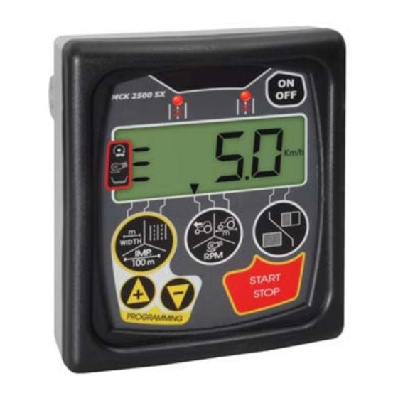
SEEDER MAT MCK 2500 SX 4. Front view MCK 2500 SX Figure 1. Front view. The front panel allows the operator to visualize all the data of the work cycle. The following elements can be distinguished: REF. DESCRIPTION Key for programming work parameters... -
Page 19: Keyboard
SEEDER MAT MCK 2500 SX 4.1 Keyboard FUNCTION KEY Programming key: Allows to program (through the keys) the parameter when selected (indicates the specific signal arrow, see chapter 3, “Programming” – pg. 22). Seeder operating width; Impulses from speed inductive sensor every 100 linear meters covered;... - Page 20 SEEDER MAT MCK 2500 SX FUNCTION KEY During the programming phase, allows to decrease the value of the parameter selected, one digit at a time (by keeping the key pressed, the values displayed will change more rapidly). During the working phase, allows to move from one “path” to the next without the need to raise or lower the row tracer disk arm on which the special magnetic sensor is installed.
-
Page 21: Programming
SEEDER MAT MCK 2500 SX 5. Programming 5.1 Programming the operating width seeding width must programmed meters MCK 2500 SX centimeters, corresponding to the width of each seeding swath: turn the computer on ( key) and keep pressing the key... -
Page 22: Programming The Calibration Of The Advancing Speed
SEEDER MAT MCK 2500 SX 5.2 Programming the calibration of the advancing speed The number of impulses from the speed sensor must be programmed MCK 2500 SX every 100 linear meters covered by the machine: turn the computer on (... -
Page 23: Practical Example For Calculating The "C" Parameter To Be Programmed
SEEDER MAT MCK 2500 SX 5.3 Practical example for calculating the “C” parameter to be programmed In the “C” parameter you have to program the number of impulses the proximity sensor has to send to the Computer every 100 linear meters the machine works. -
Page 24: Automatic Calibration Of The "C" Parameter (Recommended!)
SEEDER MAT MCK 2500 SX 5.4 Automatic calibration of the “C” parameter (recommended!) The automatic calibration for parameter “C” is carried out by covering an established distance of 100 meters, following this procedure: with the computer turned on, press the key more than once, until the second left arrow on the display appears;... -
Page 25: Programming The Number Of "Paths
SEEDER MAT MCK 2500 SX 5.5 Programming the number of “paths” For greater clarity, consult the examples in paragraph 5.5.1 on MCK 2500 SX page 27 and 28. It is necessary to program the number of swaths the seeder performs, which correspond to the swaths of the sprayer that will be used;... -
Page 26: Example For Programming The Number Of "Paths
5.5.1 Example for programming the number of “paths” By properly programming the number of “paths”, 4 different types of functions for the MCK 2500 SX computer are available: If the working width of the sprayer is divided by the working width of the seeder, an uneven number is obtained (ex. - Page 27 SEEDER MAT MCK 2500 SX If the working width of the sprayer is divided by the working width of the seeder, an even number is obtained ( ex. 12 ÷ 3 = 4 ); by programming the number obtained (4), the computer will activate the row closing device only for the swaths after the central line.
- Page 28 SEEDER MAT MCK 2500 SX If, on the other hand, through the division of the working width of the sprayer by the working width of the seeder, you get an even number (ex. 16 ÷ 4 = 4), and to start working with all the seeder completely entering from the right-hand side of the field, you must enter the parameter "no.
- Page 29 SEEDER MAT MCK 2500 SX If, on the other hand, through the division of the working width of the sprayer by the working width of the seeder, you get an even number (ex. 16 ÷ 4 = 4), and to start working with all the seeder completely entering from the left-hand side of the field, you must enter the parameter "no.
- Page 30 SEEDER MAT MCK 2500 SX If, instead, you intend using a 4 meter seeder and an 18 meter sprayer, regardless of the side from which the field will be entered, you must set the parameter "number of paths" = 18: with this particular programming, the computer will activate the closing devices in just two of the right rows of the seeder in passages no.
- Page 31 SEEDER MAT MCK 2500 SX If, through the division of the working width of the sprayer by the working width of the seeder, you get 4 (e.g. 16: 4 = 4), but you want a greater track path for the sprayer compared to that of the seeder, you must program the parameter "no.
-
Page 32: Table Of Activations
SEEDER MAT MCK 2500 SX 5.5.2 Table of activations Installation and use... - Page 33 SEEDER MAT MCK 2500 SX Installation and use...
-
Page 34: Programming The Alarms Rpms, "Speed", "Mode", "Tramline", And "Disk" Constants, And Self-Acquisition Procedure
“Tramline”, and “Disk” constants, and SELF-ACQUISITION procedure The MCK 2500 SX computer is capable of visualizing, on the display, the value of the rotations per minute (RPMs) of the turbine. It can also keep the rotations under control, and simultaneously control another secondary rotating part (distributor), as well as signal the operator when these rotating parts slow down excessively or if they stop working. -
Page 35: S", "M", "T" , "D" Constants
SEEDER MAT MCK 2500 SX 5.7 “S”, “M”, “t” , “d” constants Along with those already described in this paragraph, for a correct operation, the three constants, Speed, Mode, and Tramline (indicated by letters “S”, “M” e “t”) must also be set. The programming method remains the same: Press the key to confirm the data set, then move on to the next parameter. -
Page 36: Self-Acquisition
SEEDER MAT MCK 2500 SX By programming d=0 instead, the passage to one path to the next one occurs without the disc sensor intervention (the sensor can therefore be removed): during working operations, after pressing Start key, the passage occurs every time the advancing speed goes down to 0.0 km/h for over 15 seconds. -
Page 37: Checking Speed Sensor Operation
SEEDER MAT MCK 2500 SX = RPM distributor alarm = RPM turbine alarm NOTE: The self-acquisition procedure must only be carried out the first time the seeder is used. Afterwards, the computer keeps the rotation and alarm thresholds memorized, even if the battery is disconnected. -
Page 38: Checking Row Tracer Sensor Operation
SEEDER MAT MCK 2500 SX appears (which will probably not be constant), this means that the sensor is properly working and correctly connected. 5.11 Checking row tracer sensor operation Check the row tracer sensor as follows: Completely raise the row tracer disc arm on which the sensor to inspect)) is installed. -
Page 39: Operation
SEEDER MAT MCK 2500 SX Covering the sensor with your hand, the segment indicated by the arrow should turn off and the acoustic alarm must stop. If the computer does not perform as described in the following points, check the settings of constant “M”, the connections, and the installation of the capacitive... - Page 40 SEEDER MAT MCK 2500 SX Position the seeder at the beginning of the field, then lower the specific row tracer disk arm: it is NOT important that the lowered arm is exactly the one on which the special row tracer sensor is installed.
- Page 41 SEEDER MAT MCK 2500 SX During operation, when one of the “path” is reached which requires closing on right row, left rows or both, on the computer panel, the LED relevant to the rows that were closed will turn on, according to the following scheme:...
- Page 42 SEEDER MAT MCK 2500 SX Example: If the computer is in the fourth swath of the six programmed, by pressing the once, the computer will pass to the fifth swath. Instead, by pressing the once, the computer will pass to the third swath.
-
Page 43: Maintenance
7. Maintenance This chapter describes how to perform ordinary maintenance and extraordinary maintenance on the SEEDER MAT MCK 2500 SX. Ordinary maintenance refers to operations which must be carried out periodically. As they do not require specific skills, they can be carried out by the users (operators, etc.). -
Page 44: Troubleshooting
SEEDER MAT MCK 2500 SX 8. Troubleshooting In case of a computer malfunction, perform the simple checks below to find out what you need to do. If the problem persists, consult your local dealer or contact MC Elettronica Customer Service. - Page 45 SEEDER MAT MCK 2500 SX PROBLEM CAUSE REMEDY Row marker sensor When sowing, the flashing Check cable and cable damaged or bars on the display do not restore connection disconnected shift correctly between sectors when Row marker sensor Adjust gap as shown...
-
Page 46: Technical Data
SEEDER MAT MCK 2500 SX 9. Technical data 9.1 Seeder Mat MCK 2500 SX Power supply voltage : 10 ÷ 16 VDC Max. power absorption at 16 VDC : 8 A (not including outputs) Operating details Protection rating : IP 56... - Page 47 SEEDER MAT MCK 2500 SX 9.2.3 Ø19 Capacitive sensor Power supply voltage : 10 ÷ 30 VDC Output signal : NPN NO Max. operating frequency : 10 Hz Operating temperature : - 25°C / +70°C Max. gap : direct contact (zero gap)
- Page 48 SEEDER MAT MCK 2500 SX Electronic equipment for agricultural, earth moving and industrial machinery www.mcelettronica.it Installation and use...
Need help?
Do you have a question about the MCK 2500 SX and is the answer not in the manual?
Questions and answers