
Summary of Contents for ECHO Robotics CGSL01AF1
- Page 1 Charging Station Technical Manual CGSL01AF1 CGSL11AF1 CGSL21AF1 P/N X7507850001 VERSION 2.2 02/26/2020 ©2020 ECHO Incorporated. All Rights Reserved...
-
Page 2: Table Of Contents
ABLE OF ONTENTS Table of Contents Chapter: 1 Safety Information ......2 Safety Symbols . - Page 3 The robot has been designed to high safety standards. Risk is always possible. Read and understand all safety informa‐ tion. Genuine ECHO Robotics parts are available only from an authorized ECHO Robotics Dealer. Always supply a model and serial number when purchasing parts and assemblies. Only use and authorized ECHO Robotics Dealer for service proce‐...
-
Page 4: Safety Information
AFETY NFORMATION AFETY YMBOLS Safety Information Safety Symbols Throughout this manual and on the product itself, you Safety and Information Label will find safety alerts and helpful, informational mes‐ sages preceded by symbols or key words. The following is an explanation of those symbols and key words and Caution: The robot can be dangerous if misused. -
Page 5: Model Descriptions And Specifications
Develop an installation plan and a map of the Model Description site. Supports the Station Loop peripheral wire CGSL01AF1 Identify the location for installing the AC power only. supply, Station Loop peripheral wire(s), and Field Supports the Station Loop peripheral wire CGSL11AF1 Zone peripheral wire(s). -
Page 6: Installation Offsets
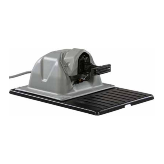
HARGING TATION NSTALLATION ROCEDURE NSTALLATION FFSETS Installation Offsets Remove the charging station from its packaging. Lift if from the base, do not lift it from the charging arm. Correct Correct Not Correct Not Correct Remove the enclosure top from the base. Range Picker applications only: Remove the If the entire field is on a slope, install the charging sta‐... -
Page 7: Peripheral Wire Installation
HARGING TATION NSTALLATION ROCEDURE ERIPHERAL NSTALLATION Peripheral Wire Installation Move the charging station to the final installation location. Place the front of the enclosure top the required distance from the station loop periph‐ Route all peripheral wires under the base and up eral wire. -
Page 8: 14 Awg Ac Wire Installation
HARGING TATION NSTALLATION ROCEDURE 14 AWG AC W NSTALLATION 14 AWG AC Wire Installation Loosen the surge protector(s) terminal screws, insert the ends of the wires into the surge protector(s) at the locations shown, securely Pull the wires through the conduit and the tighten the terminal screws. -
Page 9: Securing The Base
HARGING TATION NSTALLATION ROCEDURE ECURING THE Securing the Base Remove 0.4 in. (11 mm) of insulation from the end of each wire. Mower application only: Remove underground haz‐ Install each wire into its corresponding large ards below the charging station. Use a hammer to terminal block opening. -
Page 10: Powering On
OWERING LED I NDICATORS Powering ON LED Indicators Four LED indicators are located on the input panel on The power switch is located under the debris cover. the back side of the charger. Move the power switch to the ON position to energize IMPORTANT: If an LED is not illuminated, AC power the DC output of the charging station and the periph‐... -
Page 11: Maintenance Procedures
AINTENANCE ROCEDURES EATHER TORAGE AS INSTALLED Maintenance Cold Weather Storage or Moving (removed from installation) Procedures Move the power switch to the OFF position. During periods of wet weather, perform inspection and Turn off AC power at the mains. cleaning once per day. Remove the M5 nuts (8X) from the base of the Move the power switch to the OFF position. - Page 12 AINTENANCE ROCEDURES EATHER TORAGE OR OVING REMOVED FROM INSTALLATION Assemble a wire nut to the end of each wire. Safely secure the wires and the liquid‐tight conduit. 1 – Wire nut Remove the landscaping spikes or anchors at the charger enclosure base. Label the Station Loop, Field Zone 1, and Field Zone 2 peripheral wires, then, remove them from the surge protectors.
-
Page 13: Dimensions
IMENSIONS OWER ONFIGURATION Dimensions Mower Configuration 39.1 in. 25.4 in. 14.0 in. -
Page 14: Range Picker Configuration
IMENSIONS ANGE ICKER ONFIGURATION Range Picker Configuration 39.1 in. 25.4 in. 14.0 in. - Page 15 Cancer and Reproductive Harm www.P65Warnings.ca.gov ECHO Incorporated 400 Oakwood Road Lake Zurich, IL 60047 1-800-392-0329 www.echorobotics.com...
Need help?
Do you have a question about the CGSL01AF1 and is the answer not in the manual?
Questions and answers