
Related Manuals for PDC CERTIS B2

Summary of Contents for PDC CERTIS B2
- Page 1 ERTIS S B2: P PDT-B B2 SE ERIES RECT THER RMAL B BAR C CODE PRINT ER’S...
-
Page 2: Table Of Contents
Contents Copyright Declaration ..................1 1. Introduction ....................2 1.1 Product Introduction ................. 2 1.2 Compliances ....................2 2. Operations Overview .................. 3 2.1 Unpacking and Inspection ................ 3 2.2 Printer Overview ..................4 2.2.1 Front View ..................4 2.2.2 Interior View ..................5 2.2.3 Rear View .................. -
Page 3: Introduction
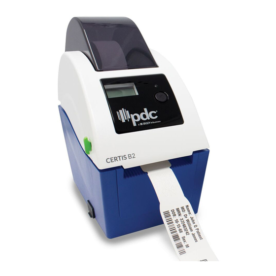
1. Introduction 1.1 Product Introduction Thank you for purchasing PDC bar code printer. Although the printer has a small footprint, it delivers reliable, superior performance. This printer provides direct thermal printing at user selectable speed of: 2.0, 3.0, 4.0 or 5.0 ips. It accepts roll feed with black mark. -
Page 4: Operations Overview
. Oper rations s Ove rview .1 Unpa acking a and Insp pection This prin nter has be een specia ally packag ed to withs stand dam age during g shipping. Please carefully y inspect th he packagi ing and pri nter upon receiving t the bar cod... -
Page 5: Printer Overview
.2 Printe er Over rview 2.1 Front V View 1. Top p cover ope en lever 2. Micr roSD card socket* 3. Me edia view w window LED indica ator . Feed butt 6. P Paper exit c chute . LCD disp play * Reco mmended M... -
Page 6: Interior View
2.2 2.2 Interio or View 1. Top co over 2. Media a holder 3. Media a guide 4. Printh 5. Gap s ensor (rec ceiver) 6. Gap s ensor (tran nsmitter) 7. Platen n roller 8. Black mark sens 9. Media a holder loc ck switch... -
Page 7: Rear View
2.2 2.3 Rear V View 1. Pow wer switch 2. Power r jack sock 3. USB B interface 4. Ethern net interfac Note: The inte erface pictu ure here is fo or reference e only. Pleas se refer to th he product s specificatio o n for the interfac... -
Page 8: Setup
3. Setu .1 Settin ng Up th he Print 1. Plac ce the print ter on a fla at, secure s surface. 2. Mak ke sure the power sw witch is set to “off”. 3. Con nect the p rinter to the e compute er with the provided U... - Page 9 4. Plac ce the roll b between th he holders and close them onto o the core. Sensor Platen roller 5. Plac ce the pape er, printing side face up, throug h the med ia guides, media sen nsor and pl lace the w wristband l...
- Page 10 7. Use “Diagnost ic Tool” to set the me edia senso r type and calibrate t the selecte ed sensor. (Star rt the “Diag gnostic too ol” Selec ct the “Prin nter Config uration” ta b Click the “Calibr r ate Sens sor”...
-
Page 11: Diagnostic Tool
.3 Diagno ostic Too The Di agnostic U Utility is enc closed in th he USB sti ick Utilities s directory. The Diag nostic Utili ty is a toolbox x that allow ws users to o explore th he printer's s settings a and status;... -
Page 12: Printer Function (Calibrate Sensor, Ethernet Setup
3. 3.2 Printe r Function n (Calibrat te sensor, , Ethernet t setup, RT TC setup… ………) 1. Sele ect the PC interface c connected with bar co ode printer 2. Click k the “Func ction” butto on to settin 3. -
Page 13: Setting Ethernet By Diagnostic Utility
.4 Settin ng Ethe ernet by y Diagno ostic Ut tility he Diagnos stic Utility i is enclosed d in USB S Stick \Utiliti es director ry. Users c can use Dia agnostic T setup the Ethernet b by USB an d Ethernet t interfaces s. -
Page 14: Using Ethernet Interface To Setup Ethernet Interface
3.4 4.2 Using Ethernet interface to setup E Ethernet in nterface 1. Con nnect the co omputer a nd the prin nter to the L LAN. 2. Turn n on the pr inter powe 3. Star rt the Diagn nostic Utilit ty by doub le clicks on n the... - Page 15 Users can also change the “Printer Name” by another model name in this fields then click “Set Printer Name” to take effect this change. Note: After clicking the “Set Printer Name” or “Set IP” button, printer will reset to take effect the settings. 8.
-
Page 16: Install Microsd Memory Card
3. .5 Insta ll Micro oSD Mem mory Ca 1. Ope en the SD m memory ca ard cover. 2. Inse ert the Micr roSD* card d into the so ocket. 3. Clos se the mem mory card c cover. * Reco mmended S D card spec... -
Page 17: Mount The Printer On The Wall
3. .6 Moun nt the P rinter o on the W Wall There are e three hole es in the b ottom of p rinter. Prin nter can be e mounted on the wal l l by the 3.0mm~3 .5mm scre ew head sc crews. -
Page 18: Led And Button Functions
4. LED and Button Functions This printer has one button and one three-color LED indicator. By indicating the LED with different color and pressing the button, printer can feed wristbands, pause the printing job, select and calibrate the media sensor, print printer self-test report, reset printer to defaults (initialization). -
Page 19: Black Mark Sensor Calibration
Power on utilities The LED color will be changed as following pattern: LED color Amber Amber Green Green/Amber Red/Amber Solid green Functions (5 blinks) (5 blinks) (5 blinks) (5 blinks) (5 blinks) 1. Black mark sensor calibration Release 2. Black mark sensor calibration, Release Self-test and enter dump mode 3. -
Page 20: Black Mark Calibration, Self-Test And Dump Mode
4.3.2 Black Mark Calibration, Self-test and Dump Mode While calibrate the black mark sensor, printer will measure the wristband length, print the internal configuration (self-test) on wristband and then enter the dump mode. To calibrate black mark sensor, depends on the sensor setting in the last print job. Please follow the steps below to calibrate the sensor. - Page 21 Self-te Printer w will print th he printer c configuratio on after ack mark s sensor cali bration. Se elf-test prin ntout can be used to ch eck if there e is any do ot damage on the hea ater eleme ent, printer configurat tions...
- Page 22 Print speed (inch/sec) Print darkne Wristband s size (inch) Gap distanc ce (inch) Gap/black ma ark sensor int tension Code page Country cod ZPL setting informatio Print darkne Print speed (inch/sec) Wristband s size Control pref ormat pref Delimiter pr refix Printer pow er up motio...
-
Page 23: Printer Initialization
Du ump mod de Printer w will enter d dump mode e after prin nting printe er configura ation. In th e dump mo ode, all characte ers will be printed in 2 2 columns as followin ng. The lef ft side char racters are received f... -
Page 24: Set And Calibrate Black Mark Sensor As Media Sensor
Parameter Default setting Speed 127 mm/sec (5 ips) (203DPI) Density Wristband Width 2” (50.8 mm) Wristband Height 4” (101.6 mm) Sensor Type Gap sensor Gap Setting 0.12” (3.0 mm) Print Direction Reference Point 0,0 (upper left corner) Offset Tear Mode Peel off Mode Cutter Mode Serial Port Settings... -
Page 25: Skip Auto.bas
The LED color will be changed as following: Amber red (5 blinks) amber (5 blinks) green (5 blinks) green/amber (5 blinks) red/amber (5 blinks) solid green 4.3.6 Skip AUTO.BAS TSPL2 programming language allows user to download an auto execution file to flash memory. -
Page 26: Troubleshooting
5. Troubleshooting The following guide lists the most common problems that may be encountered when operating this bar code printer. If the printer still does not function after all suggested solutions have been invoked, please contact the Customer Service Department of your purchased reseller or distributor for assistance. -
Page 27: Print Problem
5.2 Print Problem Problem Possible Cause Recovery Procedure Check if interface cable is well Re-connect cable to interface. connected to the interface connector. The serial port cable pin configuration is Please replace the cable with pin to pin not pin to pin connected. connected. -
Page 28: Lcd Display
5.3 LCD display This section lists the LCD display messages that you may encounter when operating the printer. Also, it provides solutions. Messages Possible Cause Recovery Procedure Head Open * The printer top cover is open. * Please close the top cover. * Running out of wristband. -
Page 29: Maintenance
6 6. Main ntenan This ses ssion pres ents the cl ean tools a and metho ods to main ntain your p printer. 1. Plea ase use on ne of follow wing mater rial to clean n the printe tton swab (Head clea aner... - Page 30 Note: Do not touch printer head by hand. If you touch it careless, please use ethanol to clean it. Please use 100% Ethanol. DO NOT use medical alcohol, which may damage the printer head. Regularly clean the print head and supply sensors once change a new media to keep printer performance and extend printer life.
Need help?
Do you have a question about the CERTIS B2 and is the answer not in the manual?
Questions and answers