
Summary of Contents for DCB AVA-E
- Page 1 AVA-E Audio/Voice Adapter User’s Guide Revised March 11, 2019 Firmware Version 2.X...
-
Page 2: Rohs
Certifications FCC Statement This device complies with the limits for a Class A digital device, pursuant to Part 15 of the FCC rules. This equipment has been tested and found to comply with the limits for a Class A digital device pursuant to Part 15 of the FCC Rules. -
Page 3: Table Of Contents
ABLE OF ONTENTS Certifications..............i FCC Statement.........i RoHS..........i Chapter 1 Introduction..........4 Applications............4 Other Features............5 Package Contents...........6 Configuration Software Requirements..6 AVA-E Hardware...........7 Front Panel..........7 Front Panel LED Indicators and Connections..........7 Indicators......7 Connections......7 Rear Panel..........8 Real Panel Connections and Switches..8 Connectors......8 Switches.......8 Chapter 2 Installation..........9 Overview..............9... - Page 4 SYNC NETWORK Port as Sync..15 Configure/Show (Async) Port (CP/SP)..........16 Configure/Show Voice (CV/SV)..16 Show Configuration (SC)....17 Show (Voice) Status (SS)....18 Activity(Counts)/Zero (AC/Z)..18 (Unit) ID...........19 Type (TY).........19 Reset (RE)........19 Load Defaults (!R)......19 Connect Remote (CR)......20 Time (TI)..........20 Repeat Last Command (*)....20 Test Tools (TT)........20 Monitor Data Port RX/TX (MR/MT)..........21 Monitor Data Port in HEX...
- Page 5 FXS/FXO (RJ11 600 ohm). .39 E&M (RJ45)......39 MIC/PTT (RJ45)....39 Cables............39 Network Port to Modem..39 Network Port to Wireless Modem.........40 Data Port to Async Device...40 Data Port to a PC Com Port. 42 Crossover Cable....42 E&M Port to Analog Modem.........42 Appendix A Specifications.........43 AVA-E Specifications..........43...
-
Page 6: Chapter 1 Introduction
2250 and 9600 bps or ADPCM (32K), PCM (64K). The AVA-E is configured via a USB Setup port using a PC with terminal emulation software or using a web browser connection. Configuration settings are maintained in non-volatile memory. -
Page 7: Other Features
Project 25 (P25) radio interoperability. This is a voice chip set that has a very long market life, which translates to a long market life for the AVA-E. AVA- E voice choices also include 64K PCM. -
Page 8: Package Contents
IP address. The default AVA address is 192.168.0.1. Configuration of the AVA-E through a serial port requires a terminal emulation program on the PC, and use of the USB connection (with the supplied USB cable) additionally requires compatible USB drivers be installed on the PC. -
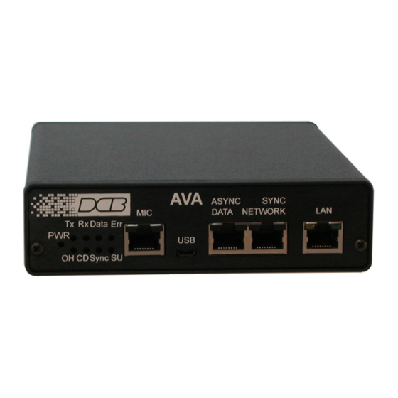
Page 9: Ava-E Hardware
Synchronous network port, and Ethernet network port. Front Panel LED Indicators and Connections Indicators POWER – is ON when the AVA-E is connected to power. Tx – Transmit Data is being sent out the network port ... -
Page 10: Rear Panel
The AVA-E is not operational while in switch 2 setup mode. If switch 2 is used for setup, connect the PC Com port to the AVA-E using the cable shown in the Cables section of this document, (Data Port to a PC Com Port). -
Page 11: Chapter 2 Installation
Telnet Setup section. The AVA-E is most easily configured using a web browser directed to its address. If the default address of 192.168.0.1 is appropriate for your local network, then plug it in and simply direct your web browser to the AVA-E and continue with configuration. -
Page 12: Parity Considerations
4 – Set internal jumper J4 to position 2,3 to route audio output to rear panel audio connector. FXS – In this mode, the AVA-E provides DC voltage and current (talk battery) for a local telephone instrument. By monitoring the presence or absence of current to the telephone instrument, the AVA-E detects... -
Page 13: Resetting Factory Defaults
E&M – In this mode, the AVA-E interfaces to the tie trunk port of a PBX, and provides a Type 1 E&M signaling interface. This is a logic level type interface, where typically the PBX places battery voltage on the M-lead to indicate an off-hook condition to the AVA-E, and the AVA-E in return, places a ground on the E- lead to indicate a busy condition to the PBX. -
Page 14: Internal Jumpers
Internal Jumpers There are several internal jumpers in AVA-E. Only jumpers J4 and J6 are typically of interest to the AVA- E user. To access the jumpers, remove the two screws from the front panel and slide the enclosure cover forward about three inches. -
Page 15: Chapter 3 Command-Line Configuration
Connections and Terminal Setup Connection to the Setup port is through the USB port on the front of the AVA-E. Use the USB cable provided to connect to a PC USB port. When connected, the AVA-E will create a COM port on the PC. -
Page 16: Configure Lan (Cl)
This Help screen shows the choice of commands available. The commands allow you to display selected options and configure the AVA-E. To leave individual options unchanged, press <Enter> to move to the next option. To return to AT YOUR COMMAND >> and abort any current changes, press <Esc>. -
Page 17: Configure/Show Network (Cn/Sn) - Sync Network Port As Async
SYNC NETWORK port set for Asynchronous operation at 115,200 bps. After making the three selections, the AVA-E will perform a Reset and return to the AT YOUR COMMAND >> prompt. To leave a setting unchanged, press <Enter>. Only the first two digits are required to select the rate. Use the SN command to display the settings without changing. -
Page 18: Configure/Show (Async) Port (Cp/Sp)
For example, if you are using a 202T modem off the data port, you may want to set the RXD holdoff to match the modem RTS/CTS delay and use the AVA-E DCD signal to drive the modem RTS signal. -
Page 19: Show Configuration (Sc)
Jitter delay is set in 20ms increments. AVA-E will perform an automatic reset at the end of the CV command, unless no values were changed. -
Page 20: Show (Voice) Status (Ss)
Show (Voice) Status (SS) Voice Status ------------------------ FXS interface enabled FXS is on-hook E&M input is on-hook E&M output is on-hook Activity(Counts)/Zero (AC/Z) Activity Counts ---------------------------- Network TX out = 0 Network RX in RX Errors Data TX in TX Errors = 0 Overflow Data RX out = 0 Voice TX in... -
Page 21: (Unit) Id
This can occur if the network is interrupted or if network end to end delays vary widely. When the jitter buffer underflows, the AVA-E has no new voice packets to send to the decoder, and the result is a glitch in the recovered audio. When an underflow is detected, the AVA-E will stop sending voice packets to the decoder until the jitter buffer again fills above the jitter level. -
Page 22: Connect Remote (Cr)
Remote AVA DISCONNECTED AT YOUR COMMAND >> Time (TI) This command displays the AVA-E up time. That is, the elapsed time since the unit was last reset. Repeat Last Command (*) To repeat the last command, simply press the key. This is handy for repeating screens of constantly changing data. -
Page 23: Monitor Data Port Rx/Tx (Mr/Mt)
Configuration Monitor Data Port RX/TX (MR/MT) Monitor data port: RX - Press ESC-ESC to quit.MT Monitor data port: RX TX - Press ESC-ESC to quit. Stop port monitor MR monitors data received on the network going out of the data port. MT monitors data coming into the data port being sent out the network port. -
Page 24: Chapter 4 Web Browser Configuration
The workstation and AVA-E must have IP addresses on the same LAN subnet. If they don't yet, connect via the USB port to configure the AVA-E to reside on the subnet of your workstation. -
Page 25: Local Lan
Client has been enabled. The DHCP server will assign the IP address. IP Port Select any desired IP port. All AVA-E units that will communicate with each other in your application must use the same IP port. Ethernet Mode This option allows you to control the Ethernet speed and duplex. -
Page 26: Remote Lan
Remote LAN Configuration Screen This is the IP address for each remote AVA-E this unit will communicate with. Up to 5 remote IP addresses can be stored. If you do not enter any remote IP addresses, this unit will transmit packets to the last IP address from which it received packets. -
Page 27: Local Voice
Local Voice Local Voice Configuration Screen Voice configuration values must match the other AVA-E units with which it communicates. As with all voice telecommunication networks, there is no set rule for the various gain values: They are installation specific and are usually compromises to obtain the highest quality voice with adequate levels and without excessive echo. -
Page 28: Notes
AVA ID The ID name of the local AVA-E unit. It may be 16 characters maximum length. Notes Voice configuration values often require adjustment for best voice quality, adequate volume, and • minimum echo. Jitter buffer adjustments are required to eliminate audio gaps or noise when... -
Page 29: Local Data Port
Local Data Port Local Data Port Configuration Screen There is a single RS-232 asynchronous port on each AVA-E unit. Data sent to this port of the local AVA-E will be received at the corresponding port of the remote AVA-E, and vice-versa. -
Page 30: Configure Users
Configure Users Configure Users Configuration Screen User names and passwords may be used to restrict administrative access to the device. Three users are defined. One user is considered the Administrative user and has full acces to the device. The other two users are restricted users and may only view the configuration. -
Page 31: Configure Access
Configuration Configure Access Access Configuration Screen Access to AVA-E configuration may be restricted by IP address. Fields Allowed IP Address Enter the IP addresses of the workstations which you wish to have access to the device. If these are left at the default of 0.0.0.0, all workstations have access. -
Page 32: Configure Snmp
SNMP functionality is meant only to provide an indication that the AVA-E unit is on-line. Fields Contact Person A text field that can be used to store the name of the person responsible for this AVA-E unit. Device Name A descriptive name for this AVA-E ... -
Page 33: Configure Summary
Configuration Configure Summary Configuration Summary This screen displays all configuration values of the AVA-E. Click buttons provide a method to reset the unit to defaults. Fields Display Fields The entire configuration is visible on this screen. Fields are described in the appropriate configuration section. -
Page 34: Port Activity
Packets Transmitted The number of packets transmitted by AVA-E to the ethernet interface Packets with errors Number of packets transmitted or received by the AVA-E through the LAN connection that contained errors. Bytes from Remote IP Addresses The number of bytes received by AVA-E from the listed IP addresses. -
Page 35: Help Screen
Configuration Help Screen Help Menu Screen There is a context sensitive help screen for each configuration screen available by clicking on the HELP button on individual configuration screens. Clicking the HELP button on the main menu screen returns this help menu screen. Fields ... -
Page 36: Chapter 5 Troubleshooting
P: When using 10/100/1000Base-T cabling, the unit does not work. S: Check the switch or hub’s link LED for the port to which the AVA-E is connected. If it is off, make sure the network cable between the AVA-E and hub is in good condition. Note that either a straight- through or crossover ethernet cable may be used. -
Page 37: Voice Problems
S: The "M" lead is the input on pin 7 of the E&M interface. With a -48 VDC in on pin 7, with the + side of the 48 volts on pin 8, ground of the RJ45 interface, the M lead relay is activated. At the far end AVA-E, pin 2, the "E"... -
Page 38: Other Problems
Other Problems P: Can’t run the initial configuration program using a serial or USB cable connection. S: Check that: Power is available and the leftmost front panel LED is on. For the USB connection, if a “Driver not found” error occurs, download the latest USB drivers for the PC, as noted in the Configuration Software Requirements section. -
Page 39: Chapter 6 Interfaces And Cables
Configuration Chapter 6 Interfaces and Cables This chapter describes electrical interfaces and commonly used cable connections. Cables Commonly used cable connections. Ethernet Cables Use any commercially available 10/100BaseT cable. If using 100BaseT or 1000BaseT, an appropriately rated cable is required. Ethernet Crossover Cable A crossover cable may be constructed to allow the ethernet port to directly connect to a PC or equivalent without using a hub or switch. -
Page 40: Port Interface
Port Interface Network Port (RJ45) Signal In/Out Receive Clock Transmit Clock Data Carrier Detect Signal Ground Transmit Data Receive Data Request to Send Clear to Send ASYNC Data Port (RJ45) Signal In/Out Data Set Ready Data Carrier Detect Data Terminal Ready Signal Ground Receive Data Transmit Data... -
Page 41: Voice Port Interfaces
Signal Ground Not Used Audio Ground Not Used Mic Audio In Not Used PTT In Cables Network Port to Modem A two foot composite to modem cable is included with each AVA-E. The pinout is as follows: Modem RJ45 DB-25P... -
Page 42: Network Port To Wireless Modem
Network Port to Wireless Modem This cables connects the AVA-E network port to a DCB wireless modem. (9802040) DCB-115 RJ45 DE-9P Data Port to Async Device Configured as DTE Computer RJ45 DB-25 Configured as DCE Computer... - Page 43 Configuration RJ-45 DB-25 6, 8...
-
Page 44: Data Port To A Pc Com Port
Data Port to a PC Com Port RJ-45 DB-25S DE-9S Crossover Cable This is for back-to-back bench testing using the asynchronous network port. AVA Network AVA Network RJ-45 RJ-45 E&M Port to Analog Modem E&M Port to Analog Modem (PCM or ADPCM) E&M Modem RJ45... -
Page 45: Appendix A Specifications
Appendix A Specifications AVA-E Specifications Data Port (“ASYNC DATA”) Port Speeds (Asynchronous only) 300, 1,200, 2,400, 4,800, 9,600, 19,200, 38,400 or 57,600 bps Port Rate Selection Selected through setup port. Data Format 10 bits/character, 1 start, 1 stop, 8 data (including parity) Interface CCITT V.24, RS-232D, implemented in RJ-45, 8 position connectors.
Need help?
Do you have a question about the AVA-E and is the answer not in the manual?
Questions and answers