Table of Contents
Advertisement
Quick Links
3951 Westerre Parkway, Suite 350
Richmond, Virginia 23233 USA
Remote I/O Module (IO-16-485)
Mounting and Wiring Instructions
This document covers the mounting and wiring of a Remote I/O Module (IO-16-485),
for expanding a VYKON
technician, or service person who is performing access system design or installation.
Please read through this entire document before beginning the installation procedures.
These are the main topics included in this document:
Product Description,
•
System Planning,
page 2
•
Preparation,
page 5
•
Precautions,
page 5
•
Installation and Start-up Outline,
•
Physical Mounting,
•
IO-16-485 Board Layout and Terminals,
•
Wiring Details,
page 10
•
Grounding,
page 10
•
Power from JACE 6-Position Connector,
•
Power from local NPB-PWR-UN module,
•
Power from third party 12–15Vdc power supply,
•
This document does not discuss mounting and wiring of other components, or software configuration. For more
information on these topics, refer to documents listed in the
Product Description
The IO-16-485 expands a Vykon JACE
8 – universal inputs (UIs), compatible with 0–10Vdc, 4–20mA, dry contacts, pulsing dry contacts,
•
0–100K ohm resistive, or Type 3 thermistor temperature sensors.
4 – digital outputs with Form-A relay contacts, for on/off control of loads up to 24Vac/dc, at 0.5A max.
•
4 – 0–10Vdc analog outputs for analog control of loads at 2.5K ohm minimum, or 4mA drain maximum.
•
The IO-16-485 module uses DIN rail mounting, and has two end-mounted 6-pin connectors that support
direct-chaining (in-line attachment) to other IO-16-485 modules.
Communications to the remote JACE uses RS-485 multidrop on 3 wires of an end-mounted 6-pin connector.
The other 3 wires on that connector are primary DC power and battery backup for the module, which can be
supplied from that same JACE (such as a J-x02-XPR-24 or JACE-700). Alternatively, you can power the
IO-16-485 locally with a DIN-mountable NPB-PWR-UN universal AC power supply, or a third-party
12–15Vdc power supply, and wire only the RS-485 bus back to the parent JACE controller.
1. JACE with NiagaraAX-3.4 or later and an available RS-485 port. See
JACE, Niagara Framework, Niagara AX Framework and the Sedona Framework are trademarks of Tridium, Inc.
Remote I/O Module (IO-16-485) Mounting and Wiring Instructions
Part Number 11156, Rev 1.3
®
®
JACE
controller. It assumes that you are an engineer,
page 1
page 7
page 7
page 9
page 11
page 12
1
with 16 I/O points that can be remotely located, including
Updated: August 20, 2014
RS-485 Communications,
•
Inputs,
page 14
•
Outputs,
page 17
•
Nrio16Module (Software)
•
Representation,
Power up and Initial Checkout,
•
Replacement Parts,
•
Replacing the IO-16-485,
•
page 13
Certifications,
•
"Related Documentation"
"System Planning,"
page 14
page 19
page 19
page 20
page 21
page 23
section on page 2.
page 2 for more details.
1
Advertisement
Table of Contents

Subscribe to Our Youtube Channel
Summary of Contents for Tridium VYKON IO-16-485
- Page 1 1. JACE with NiagaraAX-3.4 or later and an available RS-485 port. See “System Planning,” page 2 for more details. JACE, Niagara Framework, Niagara AX Framework and the Sedona Framework are trademarks of Tridium, Inc. Remote I/O Module (IO-16-485) Mounting and Wiring Instructions Part Number 11156, Rev 1.3...
-
Page 2: Related Documentation
System Planning Related Documentation Related Documentation For more information on mounting and wiring a system, refer to appropriate JACE (model) Mounting & Wiring Instructions document. For software configuration details on the I/O points provided by the IO-16-485 module, refer to: NiagaraAX NRIO Guide. - Page 3 System Planning About battery-backup operation About battery-backup operation When IO-16-485 modules are powered by JACE platforms with 6-position power/RS-485 connectors, that is, wired to the PS+, PS-, and BB terminals, they can benefit from “battery backed” protection against system power events. Note this requires the JACE to have the optional (external) sealed lead acid battery installed—as the JACE’s internal NiMH battery provides “power blip”...
- Page 4 System Planning Voltage drop considerations Voltage drop considerations When using the JACE and its backup battery to power IO-16-485 modules, and some modules are not mounted in the same enclosure with the JACE, you must be aware of voltage drops in the connecting “trunk power” cabling.
-
Page 5: Included In This Package
Preparation Included in this Package Preparation Unpack the IO-16-485 module and inspect the contents of the package for damaged or missing components. If damaged, notify the appropriate carrier at once, and return for immediate replacement (see “Returning a Defective Unit,” page 22). -
Page 6: Safety Precautions
To properly dispose of this product, please return it to your local authority collection point. If such a facility is not available, please send it to: Tridium Europe Ltd 1, The Grainstore Brooks Green Road... -
Page 7: Physical Mounting
Installation and Start-up Outline WEEE (Waste of Electrical and Electronic Equipment) Installation and Start-up Outline If installing the JACE and IO-16-485 module at the same time, please refer to the appropriate JACE Note Mounting & Wiring Guide document to install the JACE controller. The major steps to installing and starting the IO-16-485 module are outlined as follows: Physically mount the IO-16-485 module onto DIN rail. - Page 8 Physical Mounting WEEE (Waste of Electrical and Electronic Equipment) Figure 1 IO-16-485 module DIN mounting details. Mounting on DIN Rail Removing from DIN Rail NPB-PWR-UN (if used for power) Install DIN 6-position IO-16-485 rail end clip connector plug at left end of with cabling to assembly JACE and other...
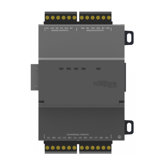
- Page 9 IO-16-485 Board Layout and Terminals About Screw Terminal Connectors IO-16-485 Board Layout and Terminals The IO-16-485 module provides 8 universal inputs, 4 digital relay outputs, and 4 0–10Vdc analog outputs. Wiring terminal positions are shown below (Figure 2), along with LED locations. Figure 2 Remote I/O Module Wiring Terminal Locations (screw terminal connectors shown installed).
-
Page 10: Wiring Details
Wiring Details Grounding Wiring Details Figure 2 to locate connectors and other components on the Remote I/O Module. Make connections to the Remote I/O Module in the following order. Connect the earth grounding wire (with spade connector) from the earth ground lug on the IO-16-485 to a nearby earth grounding point. - Page 11 Wiring Details Power from JACE 6-Position Connector Power from JACE 6-Position Connector (Not an option for JACE-2/6 series controllers) If powering one or more IO-16-485 modules from a JACE with a 6-position “Powered RS-485” connector, the 15Vdc and 12V backup battery (BB) is typically routed to the modules via a 3-conductor cable.
- Page 12 Wiring Details Power from local NPB-PWR-UN module Power from local NPB-PWR-UN module If powering IO-16-485 modules from a directly-attached AC power supply (NPB-PWR-UN module), wire the AC circuit to the NPB-PWR-UN’s 2-position terminals (must remove cover). See Figure 5, left. Disconnect power A 120Vac or 240Vac circuit powers the NPB-PWR-UN.
- Page 13 Wiring Details Power from third party 12–15Vdc power supply Power from third party 12–15Vdc power supply IO-16-485 modules can be powered by a third-party, 12V–15Vdc power supply, as an alternative to using a NPB-PWR-UN power supply module. A “battery backed” power supply is recommended. This provides power to the IO module(s) during AC power loss scenarios.
- Page 14 Wiring Details RS-485 Communications RS-485 Communications RS-485 communications from the JACE to each IO-16-485 module (or assembly of modules) requires a continuous “daisy-chain” wiring topology using a shielded, twisted-pair cable. Wire between IO-16-485 assemblies using the 6-position end connectors. At the JACE, wire to either its 3-position RS-485 connector, or if equipped, to its 6-position “Pwr/485”...
- Page 15 Wiring Details Inputs Thermistor Inputs support 10K Thermistor temperature sensors. Input accuracy is in the range of ±1% of span. By default, conversion is for a standard Type 3 thermistor sensor, with a sensor range of -10° to 135°F (23.3° to 57.2°C). Using a conversion type of “Tabular Thermistor,”...
-
Page 16: Binary Input
Wiring Details Inputs 20 mA – Inputs support self-powered 4–20 mA sensors. Input accuracy is ±2% of span, without user calibration. Figure 10 shows the wiring diagram, which requires a 499 ohm resistor wired across the input terminals. 4–20 mA sensors also require the VoltageInputPoint. Figure 10 4 to 20 mA wiring. -
Page 17: Relay Outputs
Wiring Details Outputs Figure 11 Binary input wiring. UI1 0V UI2 UI3 0V UI4 Pulse Range: Up to 20 Hz, Cut and tape shield 50% Duty Cycle wire back at sensor. Minimum dwell time > 25ms Use point: CounterInputPoint Shielded, Twisted Cable, 61m (200 ft) maximum Stud in enclosure Shield... -
Page 18: Analog Outputs
Wiring Details Outputs Figure 12 Relay output wiring diagram. 24Vac Transformer 24Vac Mains 24Vac (see previous Loads (Line) Warning) Use point: RelayOutputWritable 24Vdc Power 24Vdc Supply – D2 D3 Note that the two common DO terminals (1C2, 3C4) are isolated from each other. This is useful if controlled loads are powered from different circuits. -
Page 19: Power Up And Initial Checkout
Nrio16Module (Software) Representation Outputs Nrio16Module (Software) Representation In the NiagaraAX station interface to the JACE and IO-16-485 module, the module’s I/O is modeled in the station’s NrioNetwork (copied from the nrio palette), under a child Nrio16Module “device level” component. This Nrio16Module has a default name of “io16_n”. After a remote I/O module is discovered and added to the station under this NrioNetwork (each as one Note as an Nrio16Module), the serial status LEDs for the JACE’s RS-485 port continually flash, reflecting... -
Page 20: Standard Replacement Parts
“field replacement units,” or FRUs, with separate part numbers. If the faulty IO-16-485 is still in warranty, you can receive credit by returning it to Tridium. Be sure to contact Tridium for a return authorization (RA) number before shipping an item for return credit. See “Returning a... - Page 21 Replacing the IO-16-485 New Replacement Units Replacing the IO-16-485 Before handling circuit boards, discharge any accumulated static by touching the nearby earth Caution grounding point. For details, see the “Static Discharge Precautions” section on page 6. To replace the IO-16-485 accessory module in the field, proceed as follows: Procedure 2 Replacing the IO-16-485 accessory module.
-
Page 22: Returning A Defective Unit
For proper credit on an in-warranty unit, ship the defective unit to Tridium within 30 days. Prior to returning the unit, contact one of the following Tridium offices to obtain a return authorization (RA) number and other instructions. Please provide: •... -
Page 23: Federal Communications Commission (Fcc)
Certifications Federal Communications Commission (FCC) Certifications Federal Communications Commission (FCC) This equipment generates, uses, and can radiate radio frequency energy, and if not installed and used in accordance with the instruction manual, may cause interference with radio communications. It has been tested and found to comply with the limits for a Class A computing device pursuant to Subpart J of Part 15 of FCC Rules, which are designed to provide reasonable protection against such interference when operated in a commercial environment. -
Page 24: Ce Declaration Of Conformity
2011/65/EC (RoHS 2) Compliant 2011/65/EC I, Nino DiCosmo, President of Tridium Inc., hereby declare that the equipment specified above conforms to the above Directives and Standards. For CE compliance, the NPB-PWR-UN power supply cannot be used to power the IO-16-485 or a Note JACE (JACE 2/3E/6/6E, JACE-700). - Page 25 Tab Mounting Dimensions CE Declaration of Conformity Tab Mounting Dimensions 3.25” (82.55mm) 0.170” Dia. IO-16-485 (4.32mm) NPB-PWR-UN Note: Electronic and printed versions of this guide may not show dimensions to scale. 3.48” 2.50” 4.00” (88.55mm) (63.50mm) (101.6mm) Verify all measurements before drilling.
- Page 26 The latest product specifications can be found by contacting our corporate headquarters, Richmond, Virginia. Products or fea- tures contained herein are covered by one or more U.S. or foreign patents. This document may be copied by parties who are authorized to distribute Tridium prod- ucts in connection with distribution of those products, subject to the contracts that authorize such distribution.
Need help?
Do you have a question about the VYKON IO-16-485 and is the answer not in the manual?
Questions and answers