Table of Contents
Advertisement
Quick Links
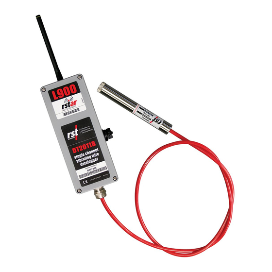
L900 RSTAR Array Radio
Series System
Instruction Manual
All efforts have been made to ensure the accuracy and
completeness of the information contained in this document. RST
Instruments Ltd reserves the right to change the information at any
time and assumes no liability for its accuracy.
Copyright © 2020. RST Instruments Ltd. All rights reserved.
Document Number: ELM0077I
Release Date:
July 2, 2020
RST INSTRUMENTS LTD.
11545 Kingston St.,
Maple Ridge, BC
CANADA V2X 0Z5
SALES + SERVICE + MANUFACTURING:
604 540 1100
|
info@rstinstruments.com
TOLL FREE (USA & Canada)
|
1-800-665-5599
www.rstinstruments.com
Advertisement
Table of Contents

Summary of Contents for RST Instruments RSTAR L900 Series
- Page 1 RST Instruments Ltd reserves the right to change the information at any time and assumes no liability for its accuracy. Copyright © 2020. RST Instruments Ltd. All rights reserved. Document Number: ELM0077I Release Date: July 2, 2020 RST INSTRUMENTS LTD.
- Page 2 DT2485 10 Channel and DT2485 40 Channel loggers updated to 2019-Dec-05 0x81 and 0x85, respectively, and GAA added to table; CE, WEEE, and Anatel logos added. DTSAA added to Table A-1, updated link 2020-Jul-02 in 3.1.1. ELM0077I RST Instruments Ltd. Page ii...
-
Page 3: Table Of Contents
Retrieving Data from the RTU .................. 14 Acknowledging Data Transmission from RTU ............15 ................16 PPENDIX XAMPLE ASIC Configuring the Number and Order of Node Loggers in RTU ........17 Reading the RTU Radio Settings ................18 ELM0077I RST Instruments Ltd. Page iii... - Page 4 Figure 4-1 Example Sensor Data File for RSTAR Network with Two DT2011B Data Loggers ....................... 8 IST OF ABLES Table 4-1 Diagnostic Data File Definitions .................. 9 Table A-1 Modbus Addresses for Different Logger Types ............15 ELM0077I RST Instruments Ltd. Page iv...
-
Page 5: Introduction
Sensor data is stored in three locations: the Node Logger, the Hub Logger, and the base station computer. RSTAR C OMMUNICATIONS RINCIPLES RSTAR networks are star type. Node data loggers send and receive data from only one Hub RTU. ELM0077I RST Instruments Ltd. Page 1... -
Page 6: Safety
DT Logger Host instruction manual (ELM0080). CAUTION ATTEMPT TO RECHARGE THE BATTERY REPLACE THE BATTERY WITH AN ALKALINE OR ZINC CARBON BATTERY EMOVE STANDARD BATTERIES PRIOR TO SHIPPING DATA LOGGERS ELM0077I RST Instruments Ltd. Page 2... -
Page 7: Installation
Follow the on-screen instructions. The default directory is: C:\Program Files\RST Instruments\DT Logger Host\ The drivers will install automatically. Refer to RST Instruments Manual ELM0080 if the drivers do not install. 3.1.2 Installing FlexDAQ Hub Logger Host Software Insert the supplied LoggerNet™... - Page 8 USB. Refer to Figure 3-2. Click the 'Install USB Driver' button on the Hardware panel. Choose the appropriate interface from the resulting dialog. Refer to Figure 3-2. ELM0077I RST Instruments Ltd. Page 4...
- Page 9 HIS PROCESS MAY TAKE UP TO MINUTES ETWORK AND IGNAL LIGHTS ON THE MODEM WILL STOP BLINKING AND TURN GREEN MIT STEPS THROUGH ONCE CONNECTED TO ™ THE CELL TOWER OGGER SETUP CAN BE VERIFIED WITH STEPS THROUGH ELM0077I RST Instruments Ltd. Page 5...
-
Page 10: Commissioning Rstar Field Data Loggers
Multi-path interference can reduce signal quality. 3.3.2 Node Data Loggers Installation • Consult RST Instruments Manual ELM0089 for RST Instruments DT series data logger installation instructions. • Antenna elevation will significantly improve radio link quality. Plan the Node Logger installations accordingly. Antennas at ankle height receive approximately an order of magnitude less signal than an antenna at waist height. -
Page 11: Assessing Radio Link Quality And Deployment
65-70. A returned value of 0 indicates no response packet was received. Press 'Stop' to cease transmission once link quality has been optimized. Press the 'Sync' button to update the Node Logger’s clock, interval, and transmission slot. ELM0077I RST Instruments Ltd. Page 7... -
Page 12: Operation
‘DT11-2_SerianNumber’ field of the diagnostic data table. Node loggers will be in ascending serial number order in the sensor data and diagnostic data tables if no modifications have been made to the RSTAR network. ELM0077I RST Instruments Ltd. Page 8... -
Page 13: File Locations
OGGER BY UPLOADING A NEW PROGRAM 4.1.4 Automatic Data Collection from FlexDAQ Hub Logger Automatic data retrieval can be set up in the LoggerNet™ 'Setup' Application for FlexDAQ Hub Loggers connected to cellular modems or radio infrastructure. ELM0077I RST Instruments Ltd. Page 9... -
Page 14: Custom Data Tables
ATA LOGGERS TO FILL IN THE GAP 4.1.5 Custom Data Tables Custom solutions are possible for data structures. Contact RST Instruments for details. 4.1.6 Addition of Node Loggers Contact RST regarding expanding the number of Node Loggers in an RSTAR network. -
Page 15: Maintenance
DT L (ELM0080). OGGER OST INSTRUCTION MANUAL AINTENANCE Refer to RST Instruments Manual ELM0088 for desiccant and battery replacement information for individual DT series data loggers. ERVICE AND EPAIR The product contains no user-serviceable parts. Contact RST for product service or repair not covered in this manual. -
Page 16: Power Requirements
The RTU response indicates whether or not the RTU is still waiting for Node data logger Transmissions. If this response is not received, the data logger should wait an appropriate interval before requesting the listening state again. Standard programs use 10 seconds between requests. ELM0077I RST Instruments Ltd. Page 12... -
Page 17: Setting The Current Time In The Rtu
‘DT<CR>’ where the order of returned date-time values is the same as write time (‘WT’) command. ETTING THE ETWORK NTERVAL Use the following command to set the network read interval: ‘INTW˽<h>:<m>:<s><CR>’ where <h> are hours, <m> are the minutes, and <s> are the second. ELM0077I RST Instruments Ltd. Page 13... -
Page 18: Determine Rstar Listening State
Table 4-1 for the identities of each the diagnostic fields. ODBUS ASTER IN AMPBELL OGGERS The Following is a general case use of the MODBUS master function for Campbell Scientific Loggers: ‘ModbusMaster(<ModbusResultVar>,<ComPort>,115200,<Modbus Address>,4,<TargetDataArray>,1,<totalChannels>,3,100)’ Contact RST if the total channels is greater than 720. ELM0077I RST Instruments Ltd. Page 14... -
Page 19: Acknowledging Data Transmission From Rtu
DTSAA 144 (0x90) 0x5A *Variable CKNOWLEDGING RANSMISSION FROM Clear the current data to allow the next transmission interval to proceed once all data has been correctly received from the RTU. Use the command: ‘ND˽1<CR>’ ELM0077I RST Instruments Ltd. Page 15... -
Page 20: Appendixb Example Crb Asic Code
+ rstarTime(5) + " " + rstarTime(6) + " " + rstarTime(7) + CHR(13) 'Package CR300 time into compatible format for RTU SerialOut(Com1,timeSendString,"",0,100) 'Send CR300 time to RTU SerialFlush(Com1) SerialClose(Com1) End If NextScan EndProg ELM0077I RST Instruments Ltd. Page 16... -
Page 21: Configuring The Number And Order Of Node Loggers In Rtu
1111 to 1115 in serial number order: ‘WLC˽-1˽11,1111 <CR>’ ‘WLC˽-1˽11,1112 <CR>’ ‘WLC˽-1˽11,1113 <CR>’ ‘WLC˽-1˽11,1114 <CR>’ ‘WLC˽-1˽11,1115 <CR>’ Note that loggers are added in the order in which the RTU receives them. The configuration must be cleared to edit the configuration. ELM0077I RST Instruments Ltd. Page 17... -
Page 22: Reading The Rtu Radio Settings
Interval , 00:10:00<CR><LF> Record Num , 0,0,0,0,0,0<CR><LF> Reset>Sleep , -<CR><LF> Buffer Cmds , -<CR><LF> Serial Num , 03100, Firmware, 1.41, 2015/11/17,11:26:33<CR><LF> Battery , 6.36,-<CR><LF> Logger Info , T,5,M,50,U,1,DT2011,5,DT2055,0,DT2040,0,TILT,0,DT4205,0,DT2350 ,0,DT2306,0,DT2033,0,DT2485:10,40,70,100,130,170,0,0,0,0,0,0<C R><LF> RTU Temp , -<CR><LF> ELM0077I RST Instruments Ltd. Page 18...
Need help?
Do you have a question about the RSTAR L900 Series and is the answer not in the manual?
Questions and answers