Table of Contents
Advertisement
Advertisement
Table of Contents

Summary of Contents for 4Links Multi-link SpaceWire Recorder Version 4
- Page 1 User Manual for the 4Links Multi-link SpaceWire Recorder Version 4 Page 1...
-
Page 2: Revision History
4Links reserves the right to change specifications or to discontinue products without notice. 4Links assumes no liability arising out of the application or use of any information or product, nor does it convey any licence under its patent rights or the rights of others. Products from 4Links Limited are not designed, intended, authorised or warranted to be suitable for use in life-support devices or systems. -
Page 3: Table Of Contents
Contents Revision History ................................ 2 Introduction .................................. 6 Product Features ..............................6 Product Options ................................ 6 General Safety Summary ............................7 1.1. Terms in this Manual ............................7 1.2. Symbols on the Product ............................. 8 2. Description of Operation ............................9 2.1. - Page 4 3.4.1. Installed Product Options ......................... 18 3.5. The RG408 Hardware Platform ........................18 3.5.1. Dimensions ............................... 18 3.5.2. Environmental Requirements ........................19 3.5.3. Power Supply ............................19 3.5.4. Handling and Transportation ........................21 3.5.5. RG Platform Firmware ..........................22 4. Block Diagram ................................. 22 5.
- Page 5 11. Statement of Volatility ............................49 11.1. Removing all information from a Unit ......................49 11.2. Security Notice ............................... 49 12. Product Limitations and Features ......................... 49 13. Regulatory Information ............................50 13.1. Electromagnetic Compatibility ........................50 13.2. Product Safety ............................... 50 13.3.
-
Page 6: Introduction
Introduction 4Links’ EtherSpaceLink family Multi-link SpaceWire Recorder (MSR) is a rack-mounted SpaceWire recorder that allows SpaceWire traffic to be captured, buffered and transmitted over Ethernet via a TCP/IP socket connection. TCP/IP is a standard interface mechanism supported by all major operating systems, so no additional software drivers are required. -
Page 7: General Safety Summary
There are no user-serviceable parts inside this equipment. Do not remove covers. Do not operate with suspected failures. If you suspect that there is damage to this product, refer to 4Links for advice. Do not operate in wet or damp conditions. -
Page 8: Symbols On The Product
1.2. Symbols on the Product The following symbol may appear on the product: Caution: Refer to this user manual for safety information. Page 8... -
Page 9: Description Of Operation
2. Description of Operation This section describes the main features of the Multi-link SpaceWire Recorder. 2.1. General The Multi-link SpaceWire Recorder (MSR) is connected to an Ethernet network and passively waits for a connection from a host computer. Connection is made using a TCP/IP socket, which is flow-controlled and is capable of recovering from errors that might occur on the network between the user and the EtherSpaceLink unit. -
Page 10: Standard Msr Capabilities
msr <IP-address-of-MSR> <filename> Use CTRL/C to stop the recording at any time. To view your recording, execute java -jar read.jar <filename> Alternatively, java -jar read.jar <filename> /s 0 provides a summary overview. You will probably need to pipe the output from this command through a paging program, such as “more” or “less”, or use the read program’s I/O parameters to direct it to a file, from where it can be viewed by a separate program. - Page 11 Figure 2.2: Connecting the MSR into a link under test The MSR electrically connects each pair of ports together, just imposing a buffering delay of about 7 ns to the signals propagating between each of these ports. No re-clocking of the signals is performed in this buffer.
-
Page 12: Summary Of Msr Options
With support from inter-unit synchronisation or an Absolute Time Interface (ATI) unit, the time-tags recorded by most members of the 4Links EtherSpaceLink family may be synchronised to an accuracy of better than 10 ns. -
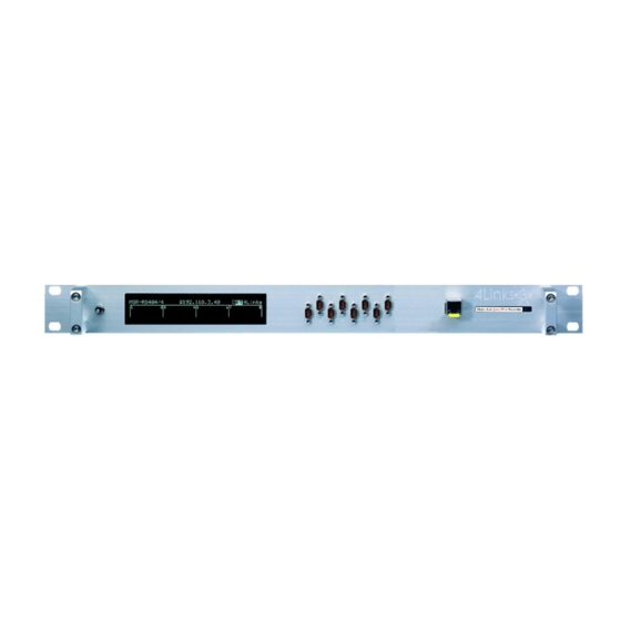
Page 13: Front-Panel Display
The MSR’s front panel display continuously monitors and displays the states of the Ethernet and SpaceWire links. The top line of the display shows the product number, the current IP address of the EtherSpaceLink unit, and the name “4Links” on the right. Figure 2.3: The MSR display 2.5.1. -
Page 14: Communication Protocols
2.6. Communication Protocols 4Links EtherSpaceLink units provide access to a SpaceWire network from computers on a conventional TCP/IP Ethernet network. TCP/IP is used over Ethernet to provide an error checked guaranteed delivery system, even through noise or the intervening network failing and being restored (for example, a cable being removed and reconnected). -
Page 15: Specification
3. Specification 3.1. SpaceWire Links The SpaceWire Links conform to ECSS-E-ST-50-12C (31st July 2008). 3.1.1. SpaceWire Receive Performance Receive speeds may be in the range from 1.2 Mb/s to more than 400 Mb/s [the lower-limit is set by the SpaceWire standard timeout period of 850 ns]. -
Page 16: Spacewire Time Codes
3.1.3. SpaceWire Time Codes SpaceWire defines a mechanism for transferring a global time reference across a network. MSR stores these time codes in its recorded data files for analysis. Page 16... -
Page 17: The Ethernet Connection
Only full-duplex Ethernet connections are supported. 3.3. SMA Synchronization Connectors Synchronization (to other 4Links units or to external devices) is achieved using SMA connectors, on units with the “-S” model number suffix where they are fitted. The rear panel of a suitably-equipped MSR contains eight SMA connectors, labelled J1 to J8 from left to right when looking at the rear panel, corresponding to software and API synchronization connections J1-J8 respectively. -
Page 18: Discovering A Unit's Serial Number And Installed Product Options
3.4. Discovering a Unit’s Serial Number and Installed Product Options 4Links EtherSpaceLink unit serial numbers are of the form A nnn (e.g. A202). The least-significant bits of the Ethernet Media Access Control (MAC) address of a unit are directly related to its... -
Page 19: Environmental Requirements
2; Indoor use only 3.5.2.1. Ventilation Requirements The 4Links RG platform products require unobstructed airflow to their rear ventilation grilles to allow the internal fans to operate efficiently and thus to allow operation across the temperature range specified in section 3.5.2, “Environmental Requirements”, above. - Page 20 Total power consumption depends on the number of active ports and options: up to around 25W. 3.5.3.3. Power Connector Power is supplied using a rear-panel-mounted 5-way 240° DIN connector with a screw-locking mechanism. Figure 3.3: The 4Links RG Platform power connector Pins Function Power (either polarity)
-
Page 21: Handling And Transportation
There are no user-serviceable parts inside this equipment. 3.5.4. Handling and Transportation The 4Links RG platform products are designed to be robust, and are capable of being transported to support SpaceWire testing. Units should be packaged in protective foam or similar material to prevent them from being subjected to excessive shocks during handling. -
Page 22: Rg Platform Firmware
Memory cards are configured for a particular 4Links hardware platform, and are only intended for use with that unit. If one attempts to boot a 4Links unit with a memory card that was built for another unit, or with a non- 4Links memory card, then the boot self-test display will display a failure message at the fifth step - which indicates that the card is unsuitable for this unit. - Page 23 Figure 4.1: EtherSpaceLink family unit block diagram Page 23...
-
Page 24: Front Panel Display
Failure during the initial four stages of the self-test usually indicates a hardware problem. Failure at the fifth stage suggests a fault with the contents of the memory card; memory cards are configured for specific 4Links units, so make sure that you have plugged the correct card into this unit. - Page 25 The lower section of the display shows SpaceWire information for each active port: SpaceWire Link status and activity: A null SpaceWire token was received on this port. These are exchanged across a link continuously when there is no other traffic to send. A data byte (an Nchar) was received on this port.
-
Page 26: Front Panel Interactions
6. Front Panel Interaction A center-biased three-position toggle switch is located to the left of the front panel display. This is used to show the unit’s serial number and options, and to set the unit’s IP address. Settings are stored in non-volatile memory and are restored when the unit is next powered-up. A single movement of the switch, either upwards or downwards, enters the first step of the user interaction where the unit’s serial number and option list is displayed. - Page 27 The state is entered via an arrowed line into the top or the side of the box. A line from the top section traces flow to the next state when the switch is pushed up. A line from the bottom section traces flow to the next state when the switch is pushed down.
- Page 28 Page 28...
- Page 29 Figure 6.3: MSR front panel states Page 29...
-
Page 30: Ip Address
6.1. IP address This section allows the unit’s IP address is to be set statically. Each set of three digits holds the value of a byte and thus may only be set between 0 and 255; attempts to set the values 256 to 299 will cycle digits within that byte and selecting “next digit”... -
Page 31: The Msr Options
The time-tags recorded by the MSR may be synchronised with those of other 4Links MSRs, DSIs and SRRs to an accuracy of better than 10 ns, and all of these may be synchronised to a time-of-day year IRIG-B00x clock using a 4Links Absolute Time Interface (ATI) unit. -
Page 32: Option Ew - Event / Error Waveforms
7.3. Option EW - Event / Error Waveforms When option EW is provided, each SpaceWire port contains a waveform recorder that captures the wire signals at that port continuously. It stops recording and makes the waveforms available after it is triggered by an event. EtherSpaceLink family units with the EW option can be set to trigger the capture of a waveform when an error is detected, and the MSR considerably extends the triggering opportunities. -
Page 33: Unit-To-Unit Time-Tag Synchronisation
8. Unit-to-Unit Time-Tag Synchronisation Multiple EtherSpaceLink units can be linked together to synchronize their internal clocks. This allows synchronised outputs across multiple boxes and time tags to be the same across multiple units. The hardware option “S” is required to provide the necessary SMA connectors on each unit that will be synchronised - e.g. MSR-RG408-MS. Units are synchronised with a daisy-chain cable between them - using rear-panel SMA connectors J7 and J8. - Page 34 Figure 8.1: Daisy-chaining the time synchronisation connections “T” indicates a 50 Ω SMA termination. The total length of cable used in the daisy-chain must not exceed 50m (165 feet). Page 34...
-
Page 35: Setting The Synchronisation Source
8.1. Setting the Synchronisation Source Each EtherSpaceLink unit waits to synchronise with a time reference unit and the chain must include ONE reference unit which provides the time for all of the others. Any EtherSpaceLink unit may be used as the time reference and must be set as such by using the switch on the front panel. - Page 36 Figure 8.3: Indication of the time synchronisation status Page 36...
- Page 37 An EtherSpaceLink Absolute Time Interface (ATI) that synchronises time-tags to an IRIG-B00x source is available from 4Links. It should be included as one of the units in the chain above. If there is an ATI in the chain, it is, by default, the synchronisation master.
-
Page 38: Software For The Multi-Link Spacewire Recorder
9. Software for the Multi-link SpaceWire Recorder Operation of the Multi-link SpaceWire Recorder falls into two distinct phases: Data Gathering, when SpaceWire traffic is collected, time-tagged and stored to a file on the host computer; Data Inspection and Analysis, which is performed after the data has been captured. 9.1. -
Page 39: Data Capture Using The Msr Program
9.2. Data Capture using the msr Program The msr program is supplied to store the data captured by the Multi-link SpaceWire Recorder into a file on the host computer. This program is provided as a pre-compiled binary executable (msr.exe) for the Windows® operating system. msr is called with two parameters and an optional third one: msr <IP-address-of-MSR>... -
Page 40: Data Inspection And Analysis Using The Read Program
9.3. Data Inspection and Analysis using the read Program The read program is supplied to convert the data that has been captured by the msr program into a range of textual forms that are suitable for human analysis or for parsing by a customer-supplied program. The read program can be used standalone, or with plug-ins for protocols. - Page 41 The read program has many other optional parameters that may be provided after the filename of the recorded file: java -jar read.jar <filename> [options] The read program’s optional parameters are listed here: /b <number> The largest block of data printed without allowing data from another flow to be printed.
- Page 42 The /s 0 parameter is commonly used immediately after making a recording to obtain a summary of the stored data. If the traffic contains SpaceWire packets longer than 2048 bytes, adding the /b <length> parameter prevents the summary line for each packet from being broken over multiple lines of output. Page 42...
-
Page 43: Example Output From The Read Program
40.0 Mbits/sec, is the user data rate; this will have been transmitted across SpaceWire at 50.0 Mbits/sec with 2 bits of protocol overhead per byte [the parity bit and the data / control flag]. //-4Links.READ (v16:20111125/v33:20110920) run by test-user on 2011-12-07 11:57:37 Z (GB) //- msr-test.msr... -
Page 44: Waveform Handling
// Added Rx protocol "RMAP" (v13:20111125) from ProtocolRx_RMAP //-4Links.READ (v16:20111125/v33:20110920) run by test-user on 2012-05-18 14:29:37 Z (GB) //- msr-test-rmap.msr /p RMAP //- PC time at start of recording was 2012-05-17 17:50:53 (daylight saving time) //- NOTE: This may not be the time of the first shown activity. - Page 45 Figure 9.1: SpaceWire waveform capture of a Link changing speed from 10 Mbps to 100 Mbps. Page 45...
-
Page 46: The Msr File Format
The need to do all of this really fast. 4Links reserves the right to change the MSR file format. If this happens, the msr and read.jar programs will be updated to reflect these changes and thus provide the stable supported interface for this product. -
Page 47: Troubleshooting Guide
Install a loopback connector on one of the ports in the pair and run a simple loop-back test to the other port in the pair, to ensure that it is connecting properly. Use the 4Links SpWIO program on an ESL or DSI or SRR unit to connect to the device-under-test manually. Page 47... - Page 48 The Synchronised Outputs option of the 4Links Diagnostic SpaceWire Interface works by inserting short idle periods into the SpaceWire signals, and for link speeds less than 100 Mb/s this can cause the disconnect timeout to be exceeded. See the DSI manual for further information.
-
Page 49: Statement Of Volatility
11. Statement of Volatility 4Links EtherSpaceLink family products do not retain any captured data after a unit is powered off. All functionality is volatile and is loaded from a memory card. Removal of the memory card and removal of power deletes all functionality from the unit. -
Page 50: Regulatory Information
13. Regulatory Information This product is for indoor use only. 13.1. Electromagnetic Compatibility This product meets the intent of EU Directive 2004/108/EC on electromagnetic compatibility. Compliance has been demonstrated to the following specifications as listed in the Official Journal of the European Union: EN 55022:2006, EN 55024:1998 inc. -
Page 51: Rg408 Product Drawings
14. RG408 Product Drawings 14.1. Plan view Plan view with front SpaceWire connectors and rear SMA connectors (not to scale): Figure 14.1: RG408 plan view with rear SMA connectors Plan 14.2. Front view Front view with front SpaceWire connectors (not to scale):... -
Page 52: Rear View
Figure 14.5: RG408 front view 14.3. Rear view With front SpaceWire and rear SMA connectors (not to scale): Figure 14.7: RG408 rear view with SMA connector Page 52...
Need help?
Do you have a question about the Multi-link SpaceWire Recorder Version 4 and is the answer not in the manual?
Questions and answers