Table of Contents
Advertisement
Quick Links
Tips
Welcome to read AheadX online document. This manual will assist you with the
installation and post-installation checking of SAGI.
Blue text, suggestions and content you may need to know
Orange text, please pay close attention
Red text, must be strictly enforced
Version
Version: V1.0
Update note: Create a document
Time: 2019.03.20
Copyright Notice
The intellectual property rights of this product and the manual are solely owned by
AheadX Technology. Without written permission, any unauthorized copying,
reproduction or sale by any organization or individual is prohibited. Please state the
source is AheadX if you quote or publish any content. The manual should not be
quoted, abridged or modified without any permission
The dimension and weight listed in this manual are approximate values based on
the design and repeated measurements.
All documents have been carefully verified to make sure the accuracy. Related
information is subject to the latest version released by the company.
The company reserves the right to change product specifications without prior
notice. Please pay attention to AheadX's official website
Registered for AheadX Technology (Beijing) Co., Ltd.
Advertisement
Table of Contents

Summary of Contents for AheadX SAGI
- Page 1 AheadX Technology. Without written permission, any unauthorized copying, reproduction or sale by any organization or individual is prohibited. Please state the source is AheadX if you quote or publish any content. The manual should not be quoted, abridged or modified without any permission The dimension and weight listed in this manual are approximate values based on the design and repeated measurements.
- Page 2 This product is not suitable for children under the age of 18. AheadX SAGI is a high quality UAV navigation flight controller. The company shall not be liable for personal injury, property loss, etc. (including direct or indirect damage) due to the following reasons: 1.
-
Page 3: Features And Applications
IMU when main IMU is not working. It supports automatic switch between dual redundancy magnetic compass and dual redundancy GNSS module. To improve its reliability, SAGI comes with all metal cover and J30J connector. SAGI adopts a decoupled extended Kalman filter, improved L1 guidance rate, and ADRC controller as core algorithm, which has extremely high precision. -
Page 4: Technical Parameters
Any installation method. SAGI comes with installing angle correction and lever arm compensation. It can be mounted at any angle and position Simulation training function. SAGI can work with AheadX's semi-physical simulator for pilot’s daily simulation training. Built-in black box data logging function, it is able to cyclically record approximately 60 minutes flight data . - Page 5 Item Maximum Standrad Minimum Unit Remarks Weight 68 * 43 * Volume 25(53 HV Supply voltage version) Power consumption Working ℃ temperature Attitude dynamic, after GNSS ° accuracy positioned Angular velocity -300 °/s measurement range Acceleration measurement range Positioning accuracy Speed measurement accuracy...
- Page 6 SBUS input Backup radio control channel data SBUS output channel Servo update frequency telemetry RS232 level, need to communication turn off built-in data interface link Voltage monitoring channel Voltage monitoring range Engine speed monitoring channel Engine speed monitoring 65535 range Used for smart battery, optical CAN interface...
-
Page 7: Interface Definition
Intel Core i3 processors, 2GB memory, 200M hard disk space or better configuration to install our ground station software Cable SAGI adopts 30J-37TJL rectangular connector with 37 durable cables. User can make cables according to the interface or buy AheadX’s finished cables. Interface definition Interface definition... - Page 8 T1: Serial port 1 , 232 use the AheadX DL900 products level GND:Ground CAN\_H: CAN bus H CAN interface, used for connecting with other AheadX's products, such as smart batteries, external magnetic compass, height-finding CAN\_H: CAN bus L radar, etc. P2+: data link positive input The voltage is the same as the flight control...
- Page 9 PWM2:PWM channel2 PWM3:PWM channel3 PWM4:PWM channel4 PWM5:PWM channel5 PWM6:PWM channel6 PWM7:PWM channel7 PWM8:PWM channel8 PWM9:PWM channel9 PWM10:PWM channel10 GND: Ground Ground SBusOut:SBus Used to control the servo or ESC control output AD1: Voltage monitoring channel 1 AD2: Voltage monitoring channel 2 Voltage must be less than 58V GND: Ground, for voltage monitoring...
- Page 10 T5: Serial port 5 transmission, RS232 level GND: Serial port Ground Precautions Please pay attention whether the power GND and signal GND are connected or not when using ESC. You may meet following problem if the power GND and signal GND are connected: high current may be led back to flight controller via the signal GND cable if power GND cable with any cold soldering or virtual open circuit, which may cause the flight controller to be burnt.
- Page 11 For example, when connecting nacelle to COM5, user can make self-recovering fuses connected in series with its GND cable. This will ensure flight controller will not be affected by external equipment failure. Please ensure that the voltage or power input and output between all pins meet the above requirements, otherwise the flight control or other avionics equipment will be burnt.
- Page 12 Otherwise it may cause flight controller to be burnt. Data link SAGI: data communication RS232 level. Cable【8】【9】【10】 are serial port data receiving, serial port data transmission and GND. The LINK interface is used for data communication and firmware upgrade.
- Page 13 PWM servo connection Quad Plan PWM servo connection SAGI-QP supports 4 channels of PWM multi-rotor ESC input, 6 channels of servo/ESC input. PWM output signal does not correspond to RC travel. PWM signal here is completely controlled by the flight controller. You can ignore the radio control output sequence There are strict requirements for the ESC connection of the multi-rotor part.
- Page 14 Fixed wing PWM servo connection SAGI-FW provides 10 channels for PWM servo / ESC . PWM output signal does not correspond to RC travel. PWM signal here is completely controlled by the flight controller. User can ignore the radio control output sequence.
- Page 15 PWM-3 number 【20】: elevator; PWM-4 number【21】: rudder; PWM-5 number 【22】: throttle; PWM-6 number 【23】: Camera shutter Signal connection example Multi-rotor ESC connection SAGI-MR supports a variety of multi-rotor configurations and provides 8-channel PWM multi-rotor ESC input. The connection sequence as follows:...
- Page 16 ...
- Page 17 SBUS connection SAGI has specially designed a 16-CH SBUS signal, which is independent of 10 channels of PWM output, it can connect SBUS servos and extend the servo control PWM output signal does not correspond to RC travel.
- Page 18 Auxiliary joystick User can use a radio control to assist SAGI to control the drone. There are two ways to do that. Please choose the appropriate way according to your requirement. 1.Receiver connects to data link: supports SBUS-to-USB module to upload radio control signal to AheadX Space.
- Page 19 Recommended shock absorption structure: AheadX has designed shock absorbers for SAGI , which are standard and professional version. The standard (DMP307STD01) adopts a rubber shock absorbing structure that is...
- Page 20 The professional (DMP307PRO01) adopts an advanced shock absorbing gel structure with complete shock absorption performance,which is compact and easy to install. Suitable for drones used in harsh environment. SAGI standard shock absorber (DMP307STD01) SAGI professional shock absorber (DMP307PRO01) ...
- Page 21 3. Keep away from radio transceivers with high radiant power. The metal shell of SAGI system comes with better anti-interference feature. But we still recommend user to avoid possible electromagnetic field interference during installation. The magnetic compass is very sensitive to magnetic fields, so it is susceptible to abnormal magnetic field interference which may affect data accuracy.
-
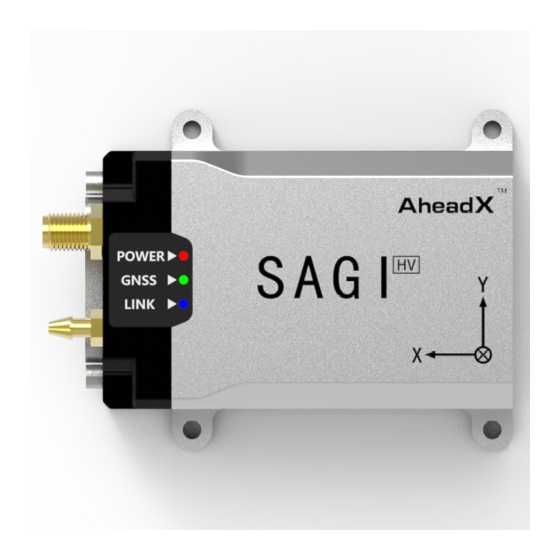
Page 22: Indicator Light
Indicator light Flight control installation Installation Environment Electromagnetic Compatibility The equipment may interfere the compass: engine, motor, gimbal, power supply cables, magnetic screws and other metal components. a) Away from engine. Engine will interfere compass and the vibration from generator will interfere flight controller b) Motor and gimbal will generate strong magnetic interference when they are working, which will strongly interfere compass stability... - Page 23 d) Magnetic screws and larger metal structures will cause constant deflection interference to the magnetic compass. Any power supply cable or magnetic screws cannot be mounted within 10cm around the flight controller. Motors, gimbals and other magnetic devices cannot be mounted within 15cm around FC.
- Page 24 (that is, the sum of the absolute values of all the installing angle adjustment parameters is the smallest). IIn order to obtain better measurement accuracy, SAGI should be mounted within 1 m of the center of mass. Common installation examples:...
- Page 25 ...
- Page 27 Flight control and cable connection...
-
Page 28: Installation Adjustment
SAGI uses the J30J connector, which leads to more cables, so user needs to pay attention to the following items Tie up cables into bundles and take anti-interference measures according to specific situation. When connecting the cable to the flight controller, do not pull or push the flight control to avoid an unpredictable error due to the force. - Page 29 GNSS measures the position and speed of the antenna mounting point. It will cause lever arm effect and measuring error if GNSS mounting position doesn’t overlap TAURUS mounting position. In some cases, user may need to correct the mounting position and input the coordinate distance. (The distance of GNSS relative to FC). ...
-
Page 30: Post-Installation Check
Including but not limited to the above situation, for any product degradation, failure, damage and crash caused by user who didn’t check TAURUS and its accessories and didn’t install the flight controller according to our manual. AheadX does not assume any responsibility for direct or indirect damage caused by such circumstances. -
Page 31: Basic Test
Basic test This chapter will introduce basic tests on the use of flight control. Refer to this chapter for post-installation testing. Hardware connection check Air unit System power supply: Power supply: please make sure power connection is correct and voltage is within the 7-53V. PWM connection: Quad plane** Please confirm that PWM 1~4 connected to multi-rotor ESC ;... -
Page 32: Pre-Flight Check
User can use offline map if Internet disconnected Pre-flight check The AheadX Space V3 ground station features with a complete pre-flight check. Please readAheadX Space V3 Groud control software manual-- find “Pre-Flight Check”, user should do the pre-flight check according to the guidance. -
Page 33: After-Sales Policy
After-sales policy User can request a return& refund service within seven (7) calendar days of receiving a product if the product has a manufacturing defect. AheadX provides one-year warranty. You can request a return& refund service where: Provide a legal proof of purchase, receipt, bill, invoice or order number;... - Page 34 AheadX provide one-year warranty which starts from the day of purchase Free repair service if the products has a manufacturing defect Free lifetime software upgrade. Send back postage is on user’s side. (Return postage is on AheadX’s side). The following items are included in the one-year warranty period: Warranty project...
Need help?
Do you have a question about the SAGI and is the answer not in the manual?
Questions and answers