Table of Contents
Advertisement
Quick Links
Advertisement
Table of Contents

Summary of Contents for Altaros AUTOMATIC TURRET TOOL HEAD FOR EIGHT TOOLS
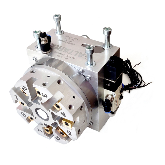
- Page 1 Instruction manual AUTOMATIC TURRET TOOL HEAD FOR EIGHT TOOLS ALTAROS...
-
Page 2: Table Of Contents
CONTENT INTRODUCTION AND DESCRIPTION ........- 2 - PREPARATION ..............- 3 - 2.1..........- 3 - TTACHING TO THE LATHE 2.2............. - 4 - OOLS ATTACHEMENT 2.3....- 6 - TTACHING OF PRESSURE AIR AND COOLING FLUID 2.4. -
Page 3: Introduction And Description
1. INTRODUCTION AND DESCRIPTION Automatic turret tool head ALTAROS is designed for quick exchange of eight tools on a classic or CNC lathe. Positioning of tools is performed by... -
Page 4: Preparation
Tools are rotating clockways and every position have its number. 2. PREPARATION 2.1. Attaching to the lathe First, remove the original tool holder on the lathe slide. Then it is necessary to manufacture a plate for attachment to the original slide to get the right high so that the axis of the turret head is at the level of the main axis of the lathe. -
Page 5: Tools Attachement
2.2. Tools attachement Attach elongated tools, such as turning tools, to the rectangular cutouts from the front side. It is highly recommended to shorten the length of these tools to a minimum, reducing the load on the turret head and increasing rigidity and accuracy. Grooves are made for tools with a height of 12 mm, larger tools need to be milled to this size. - Page 6 Tools in direction of main axis, such as drills, are attached to the tool cubes into holes or chucks (technical documentation in the attachment). To attach them to the tool head, press the bottom of the cube onto the flat surface on side of the head so that it fit into the cutout.
-
Page 7: Attaching Of Pressure Air And Cooling Fluid
It is right to place the long tool two positions away from the short one. FIG. 4 Correct placement of tools We recommend you to place a combined facing and roughing tool on the first position, grooving second and the threading third, which do not need to be removed can be permanently mounted. - Page 8 through a 6 mm hose. The upper valve wheel adjusts the required fluid flow and the lower locks the selected setting. A thin sheet metal plate is used to direct the liquid onto the frontal tools, before use drill a 1.5 - 2 mm hole as needed. It must reach the inner channel.
- Page 9 FIG. 6 Connecting scheme - 8 -...
-
Page 10: Manual Tool Positioning
2.4. Manual tool positioning Before each tool positioning, move the slide away from the workpiece in both axes to avoid a collision of longer tool with the workpiece. In the case of drill bits and front blades, note that when exchanging the tools, the tool head extends of 7 mm! The current tool is replaced by manual activation of the solenoid valve mounted on the leftside. -
Page 11: Automatic Control
3. AUTOMATIC CONTROL 3.1. Wiring connections The turret head in automatic mode is controlled by the opto-isolated breakout board with the parallel port and two relays. The power source have to converts the mains voltage to 12V. The signals from the computer are routed via a parallel port to the isolated board, which is powered from the 12V power supply. - Page 12 FIG. 8 Connecting of the board - 11 -...
-
Page 13: Software Praparation
3.2. Software praparation The Mach 3 program is designed as a control program, which has to be installed on the control computer. After successful installation, the control electronic can be connected to the computer. The new device can be found via Control Panel. You have to select the active pins in the program. - Page 14 FIG. 10 Input setting FIG. 11 Output setting Select the Diagnostic button on the Mach3 front page. With the correct setting and wiring, the indicator light below the Inputs of Active 4 should glow green on the odd-numbered positions of the tool head.
-
Page 15: Control Macros
Download and extract the file M6Start.m1s and save it to the Mach3 folder under the macros into the sub-file you are using to control. An example of pathname when... -
Page 16: Coolant Control
(tool on head position No. 5, in table under No. 21, rotation start). 3.4. Coolant control If a coolant supply is required, a small pump can be connected. During installation, the device must not be live and work may be carried out by a skilled person. -
Page 17: Operation On Cnc Lathe
On the Output Signals tab, find the line where is the Output with selected number (Output # 3), click on Eneable, overwrite Port # to 1 and Pin Number to 1. FIG. 14 Output signals - flood For fluid switching, the M8 and M9 codes are used, where M8 starts the coolant supply and M9 switches off, liquid shutdown is required during each tool change! -
Page 18: Running The Program For The First Time
position on the tool head in the range of 1-8. Use the Tool Adjust button for any tool changes in the tool table to enter the tool number from the tool table into Current Tool box. Once you've finished editing, return to the Cycle environment, manually positioning to Tool 1 and override Tool No. -
Page 19: Maintenance Instructions
MAINTENANCE INSTRUCTIONS 4.1. Lubrication In case of a change in usual mechanism behavior, it necessary to lubricate the internal mechanism. Unscrew the cover plate on the back. And apply silicone oil inside. 4.2. Cleaning Before attaching the tools it is necessary to clean the contact surfaces so that the dirt does not deflect the tool and the accuracy is not impaired. -
Page 20: Troubleshooting
FIG. 15 Tapered seating surfaces 5. TROUBLESHOOTING 5.1. Errors If the program is stopped and an error message is displayed, the program has evaluated that the instructions have been misspelled, or the rotating head has behaved unusualy. Error messages with timestamps can be found in the Diagnostic tab on the Home screen under the history button (FIG. - Page 21 Turret out of scale. E stop This message will appear if there is a wrong value in Tool No. box a value of 0, or a number greater than 8 is not accepted. It is necessary to manually position to Tool 1 after resetting (if not already) and to the Tool No.
-
Page 22: After Turning, The Head Does Not Retract
can be verified in the Diagnostic window, where the Active 4 field should be lit at odd positions. (FIG. 12) 5.2. After turning, the head does not retract Make sure that the pressure inside conection hose have the right value. 5.3. - Page 23 Steel Pin Replacement: First, unscrew the long Allen screw (1) that partially extends over the plate in the cutout on the top of the base (2). Remove the sheet metal cover from the top which is held by magnet and open the view on the cylinder with the pin from above.
- Page 24 quick coupler back (5). Before securing the side bolt, push the cylinder down and press on the raised bolt heads to push the cylinder so that the pin approaches the back of the base and the quick coupler rests against the left side of the hole when viewed from the side.
-
Page 25: Technic Data
6. TECHNIC DATA Recommended pressure 58-60 PSI / 4-4.2 bar, for longer life, MAX 5 bar / 72 PSI Voltage DC 12 V Recommended cutting force 500 N, MAX 650 N A – Fluid inlet B – Pressurized air inlet C –... -
Page 26: Drawings
7. DRAWINGS 7.1. Tool Cube The height of the rectangular protrusion is 5 mm, choose the height of the cube according to the tools you want to place into the cube. - 25 -... -
Page 27: Coolant Plate
7.2. Coolant plate - 26 -... -
Page 28: Warranty Conditions
The warranty does not cover consumables (seals). Furthermore, the manufacturer is not liable for damages to health and property due to improper use or handling that is inconsistent with this manual or sudden isolated failure. Altaros Air Solutions s.r.o. Liberec, Česká Republika www.altaros.cz E-mail: airgun@altaros.cz...
Need help?
Do you have a question about the AUTOMATIC TURRET TOOL HEAD FOR EIGHT TOOLS and is the answer not in the manual?
Questions and answers