Table of Contents
Advertisement
Quick Links
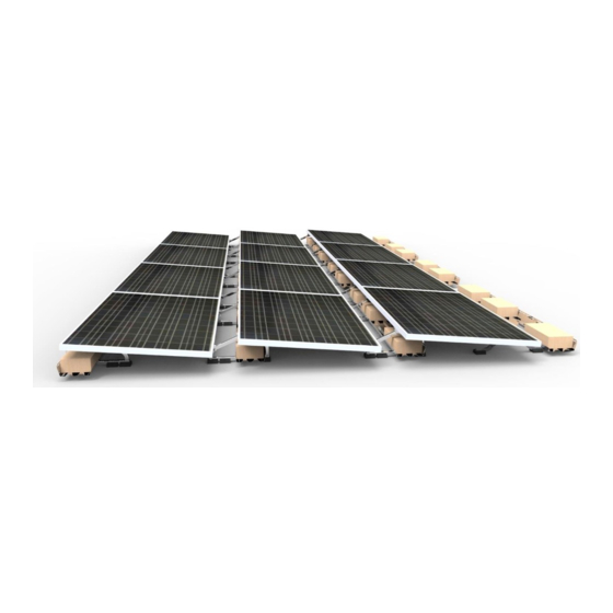
Polar Bear® III HD 5 Degree
Installation Manual
Document Number 9910034 Rev F
Jan 2019
System Fire Class Rating: Class A for low slope roofs with Type I & Type II Modules
Mechanical Load Rating: See
panelclaw.com
Appendix C: UL 2703 Electrical Grounding
PanelClaw®, Inc.
1600 Osgood Street, Ste. 20-23
North Andover, MA 01845
Tel +1 (978) 688.4900
www.panelclaw.com
Advertisement
Table of Contents

Subscribe to Our Youtube Channel
Summary of Contents for PanelClaw Polar Bear III HD 5 Degree
- Page 1 PanelClaw®, Inc. 1600 Osgood Street, Ste. 20-23 North Andover, MA 01845 Tel +1 (978) 688.4900 www.panelclaw.com Polar Bear® III HD 5 Degree Installation Manual Document Number 9910034 Rev F Jan 2019 System Fire Class Rating: Class A for low slope roofs with Type I & Type II Modules...
-
Page 2: Revision History
C00480 03-FEB-17 “10D” respectively Added Appendix G for Shim Pad Installation C00522 29-JAN-18 Add “OMG Universal” to MA listing Brand Refresh. Corrected “figure” C00546 03-JAN-19 numbering on page 27 Polar Bear III HD 5 Degree Installation Manual 9910034 Rev F... -
Page 3: Table Of Contents
Appendix D: Electrical Grounding (UL 2703 not applicable) ............... 22 Appendix E: UL 2703 Fire Classification ...................... 24 Appendix F: Ballast Blocks ........................... 26 Appendix G: Shim Pad Installation ......................27 Polar Bear III HD 5 Degree Installation Manual 9910034 Rev F... -
Page 4: Introduction
This section does not claim to address or support all safety concerns that may arise during the installation of PanelClaw mounting systems or any other aspect of the work being performed. Before beginning work, installers should refer to all local and federal safety, health and regulatory requirements to assure compliance. -
Page 5: Parts And Hardware
PowerGrip Shim Pad Appendix F: Ballast Blocks) PowerGrip Plus Microinverter Attachment Kit PowerGrip Universal Optimizer Attachment Kit EcoFasten® Solar Ground Lug Anchor Products U-Anchor 2000 U-Anchor 2400 U-Anchor 2600 Polar Bear III HD 5 Degree Installation Manual 9910034 Rev F... -
Page 6: Required Tools
Torque Setting Fastening Operation 8-10 ft-lb (96-120 in-lb) All connections 2 ft-lb (25 in-lb) Attaching ground lug to Ballast Tray 3.75 ft-lb (45 in-lb) Attaching bonding jumper to ground lug Polar Bear III HD 5 Degree Installation Manual 9910034 Rev F... -
Page 7: Installation
2.2. Reference the Q and L dimensions on the Racking Construction Set drawing. Set two spacer stick brackets to the Q dimension and 2 spacer stick bracket to the L dimension. Polar Bear III HD 5 Degree Installation Manual 9910034 Rev F... -
Page 8: Step 3: Build Northern Row Of Modules
4x Adjustable Spacer Stick Bracket Figure 2 Spacer Stick Step 3: Build Northern Row of Modules Polar Bear III HD 5 Degree Installation Manual 9910034 Rev F... - Page 9 This Ballast Tray connects the first two columns of modules. A TRAY SHOULD ALWAYS BE INSTALLED BETWEEN TWO MODULES SO THAT THE COLUMNS OF MODULES ARE CONNECTED TOGETHER. (Figure Polar Bear III HD 5 Degree Installation Manual 9910034 Rev F...
- Page 10 (96-120 in-lb). Use the Spacer Stick to keep the Ballast Tray perpendicular to the Supports while maintaining spacing between Supports. (Note there are three bolts required to connect a tray to each individual support, one fastener per slot). Polar Bear III HD 5 Degree Installation Manual 9910034 Rev F...
- Page 11 3.16.Repeat steps 3.10 through 3.15 for the entire row. A support turned upside down and placed between modules may be used to ensure that a 1”spacing is maintained between columns (if Ballast Trays are not secured to Supports prior to module installation). Polar Bear III HD 5 Degree Installation Manual 9910034 Rev F...
- Page 12 NOTE: Do not fasten Long Ballast Trays together where they overlap in midair. Secure Ballast Trays together only when two Ballast Trays overlap on the same Support (all end of rows). Polar Bear III HD 5 Degree Installation Manual 9910034 Rev F...
- Page 13 3.18.Install required ballast into the second row of Ballast Trays and bend up the end tabs located at the end of each Ballast Tray (Figure 8). Reference the Racking Construction Set to determine ballast quantity and proper placement per Ballast Tray. Polar Bear III HD 5 Degree Installation Manual 9910034 Rev F...
-
Page 14: Step 4: Install Array Row-By-Row
Where a long Ballast Tray is specified at the end of the row it should appear flush with the module. When a short Ballast Tray is specified at the end of the row it should appear centered on the module. Polar Bear III HD 5 Degree Installation Manual 9910034 Rev F... - Page 15 Rivet Nuts and torque to 8-10 ft-lb (96-120 in-lb). End Ballast Tray is centered on module Torque all bolts to 8-10 ft-lb (96-120 in-lb) Ballast Trays are centered on module Figure 10 Installation of the South Tray Polar Bear III HD 5 Degree Installation Manual 9910034 Rev F...
-
Page 16: Step 5: Electrical Grounding
Appendix C: UL 2703 Electrical Grounding. Additional information regarding UL 2703 and the specific list of evaluated modules included in PanelClaw’s UL listing can be found in the “PB3 HD UL Overview and Module Listing” document (available at www.panelclaw.com). For modules that have not been evaluated for use with Polar Bear III HD 10 Degree, please follow the instructions below in Appendix D: Electrical Grounding (UL 2703 not applicable). -
Page 17: Appendix A: Safety
The subsections below outline some of the obvious / major hazards that could exist during the installation of PanelClaw products, and are divided to bring a level of clarity to such hazards. Some sections do not apply to all PanelClaw product lines and such exclusions are noted within each section. - Page 18 All required tools to perform the installation of PanelClaw racking are outlined in the installation procedure. All tools should be inspected daily and before use by the operator. If any tool appears to be defective, stop the use of such equipment immediately, and ensure it is replaced before work continues.
-
Page 19: Appendix B: Special Configurations
2. Shim Pads must be placed where the end of the Ballast Tray comes in contact with the roof. A Shim Pad must be installed in one of the two holes in the end of the Ballast Tray. These two holes allow for different heights of shimming. Polar Bear III HD 5 Degree Installation Manual 9910034 Rev F... -
Page 20: Appendix C: Ul 2703 Electrical Grounding
Appendix C: UL 2703 Electrical Grounding The Polar Bear III HD 5 Degree flat roof system may be used to ground and/or mount a PV module complying with UL1703 only when the specific module has been evaluated for grounding and/or mounting in compliance with the included instructions. - Page 21 Once the groupings of strings at equipotential have been determined, a Tyco solid wire grounding assembly must be attached to one Ballast Tray within each group of strings. PanelClaw’s Polar Bear Ballast Trays have a hole to which this grounding device/lug can be attached (see Figure 13).
-
Page 22: Appendix D: Electrical Grounding (Ul 2703 Not Applicable)
Appendix D: Electrical Grounding (UL 2703 not applicable) The Polar Bear III HD 5 Degree flat roof system must be electrically bonded to the other DC grounding paths. System Ground Path The system ground path follows through the Module to the Tyco lug into the ballast tray via a solid #12 or #10 AWG Cu bonding jumper. - Page 23 Grounding Instructions: PanelClaw components within the array are required to be electrically bonded to other DC grounding paths via the use of either a #12 or #10 AWG Cu bonding jumpers and a UL 467 listed Tyco solid wire grounding assembly, part number 2106831-1, manufactured by Tyco Electronics Corporation. The conductor size should be selected in accordance with NEC 690.45 and NEC 250.122.
- Page 24 To Adjacent Ballast Tray Ballast Tray Racking Ground Racking Ground Connection Detail Module Ground Connection Detail Ground Lug Tyco #2106831-1 To DC Grounding Path Figure 16 Bonding and Grounding Instructions Polar Bear III HD 5 Degree Installation Manual 9910034 Rev F...
-
Page 25: Appendix E: Ul 2703 Fire Classification
The system has a Fire Class A rating for low slope roofs with Type I and Type II modules when the following requirements are met: • System is installed over a fire resistant roof covering rated for the application (UL2703, 26.3B) • Roof slope is less than 2”/ft Polar Bear III HD 5 Degree Installation Manual 9910034 Rev F... -
Page 26: Appendix F: Ballast Blocks
Appendix F: Ballast Blocks PanelClaw does not provide the ballast blocks required to construct the system in accordance with PanelClaw’s Racking Construction Set drawings. We do, however; maintain a list of potential block suppliers across the country. IT IS ABSOLUTELY CRITICAL THAT WHEN PROCURING BALLAST BLOCKS FOR ANY BALLASTED ROOFTOP SYSTEM THAT IT BE MANUFACTURED TO RESIST FREEZE-THAW AS REQUIRED BY LOCAL CONDITIONS AND FOR IT TO BE ABLE TO MAINTAIN ITS WEIGHT OVER THE LIFE OF THE SYSTEM. -
Page 27: Appendix G: Shim Pad Installation
Attach the Shim Pads to the support pads. The flat edge of the pads should face each other when installing Shim Pads on PBIII HD 5D Supports Figure 17 Install Shim Pad Polar Bear III HD 5 Degree Installation Manual 9910034 Rev F...
Need help?
Do you have a question about the Polar Bear III HD 5 Degree and is the answer not in the manual?
Questions and answers