
Summary of Contents for EDAN INSTRUMENTS DUS 6
- Page 1 EDAN INSTRUMENTS, INC Manual Ver: 1.4 Release Date: Jan. 2010 Part Number: MS1R-102299-1.4...
- Page 2 P/N: MS1R-102299-1.4 Copyright © Copyright EDAN INSTRUMENTS, INC. 2008-2010. All rights reserved. Statement This manual will help you understand the operation and maintenance of the product better. It is reminded that the product shall be used strictly complying with this manual. User’s operation failing to comply with this manual may result in malfunction or accident for which Edan Instruments, Inc.
- Page 3 WARNING A WARNING label advises against certain actions or situations that could result in personal injury or death. CAUTION A CAUTION label advises against actions or situations that could damage equipment, produce inaccurate data, or invalidate a procedure. NOTE: A NOTE provides useful information regarding a function or a procedure. Revision History Date ECO#...
-
Page 4: Table Of Contents
Table of Contents Chapter 1 Introduction ........................1 1.1. Intended Use........................1 1.2. Features ..........................1 1.3. Model ..........................2 1.4. Contraindication....................... 2 1.5. General Safety Precaution Information................2 1.5.1. General Information ....................2 1.5.2. Biohazard Considerations ..................3 1.5.3. Electrical Safety ...................... 3 1.6. - Page 5 5.4.6. Body Mark Function ..................... 29 5.4.7. Adjustment Controls ..................... 31 5.4.8. Imaging Functions....................33 5.4.9. Additional Control Functions................35 5.5. Menu ..........................35 5.6. Dialog Box Operation ....................37 5.7. Presetting........................38 5.7.1. Entering and Exiting ..................... 38 5.7.2. Displaying / Modifying the Preset Parameter ............38 5.7.3.
- Page 6 7.3. Fetus Growth Measurement ................... 78 7.3.1. GS.......................... 79 7.3.2. CRL ........................79 7.3.3. BPD ........................79 7.3.4. HC ......................... 80 7.3.5. AC ......................... 80 7.3.6. FL .......................... 81 7.3.7. AFI ........................81 7.3.8. TAD........................81 7.3.9. APAD ........................82 7.3.10.
- Page 7 9.1.6. UT-L/CX-L......................112 9.2. Gynecologic Report ..................... 112 9.3. Others ........................... 113 Chapter 10 Small Parts Measurement and Calculation............... 114 10.1. Measurement and Calculation................... 114 10.2. Small Parts Report..................... 115 10.3. Others ........................115 Chapter 11 Urology Measurement and Calculation..............116 11.1.
- Page 8 A2.1: Ultrasound in Medicine....................136 A2.2: Ultrasound Safety and the ALARA Principle ............136 A2.3: Probe Acoustic Output Parameters List ..............138 A2.3.1 : Test of Probe C363-1 ..................138 A2.3.2 : Test of Probe L743/E743 ................139 A2.3.3 : Test of Probe C321..................140 A2.3.4 : Test of Probe E613 ..................
-
Page 9: Chapter 1 Introduction
The DUS 6 is intended for use by or on the order of a physician or similarly qualified health care professional for ultrasound evaluation of Fetus; Abdomen;... -
Page 10: Model
DUS 6 Digital Ultrasonic Diagnostic Imaging System User Manual 1.3. Model DUS 6 1.4. Contraindication The equipment is not applicable to the diagnosis of the pneumatic organs that contain gas such as lung, stomach, intestines, etc. It is recommended not to examine the parts with wounds or acute inflammation to avoid cross infection. -
Page 11: Biohazard Considerations
Long time exposure should be avoided. For the parameters of sound output, please refer to appendix A. The DUS 6 complies with the requirements of applicable International Electrotechnical Commission (IEC) standards in terms of safety and acoustic output levels. - Page 12 The recommended inspection interval is once per week or less. If damage is evident, replacement is recommended before use. Equipment connected to the DUS 6 and located in the patient zone must be powered from a medically-isolated power source or must be a medically-isolated device.
- Page 13 Ultrasound machines also generate EMI. The DUS 6 complies with limits as stated on the EMC label. However, there is no guarantee that interference will not occur in a particular installation.
-
Page 14: Labeling Symbols
DUS 6 Digital Ultrasonic Diagnostic Imaging System User Manual Transformer Defibrillator Wireless LAN equipment Medical lasers Scanners Cauterizing guns Computers Monitors Fans Gel warmers Microwave ovens Light dimmers Portable phones The presence of a broadcast station or broadcast van may also cause interference. - Page 15 DUS 6 Digital Ultrasonic Diagnostic Imaging System User Manual General Symbol for Recovery / Recyclable Federal (U.S.) law restricts this device to sale by or on the order of a physician. Authorized Representative in the European Community The symbol indicates that the device complies with the European Council Directive 93/42/EEC concerning medical devices.
-
Page 16: Chapter 2 System Overview
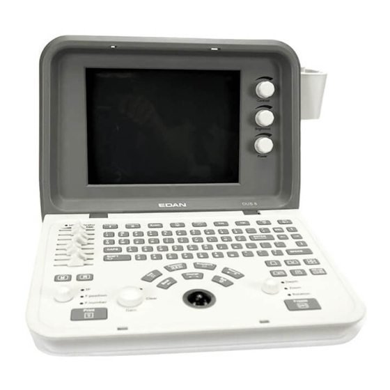
DUS 6 Digital Ultrasonic Diagnostic Imaging System User Manual Chapter 2 System Overview 2.1. Appearance 2.1.1. Front Panel Figure 2-1 Front Panel Schematic Diagram 1. Probe holders 2. Display screen 3. Contrast adjustment knob 4. Brightness adjustment knob 5. Acoustic power adjustment knob 6. -
Page 17: Rear Panel
DUS 6 Digital Ultrasonic Diagnostic Imaging System User Manual 2.1.2. Rear Panel Air Fan: Heat emission fan Figure 2-2 Rear Panel Schematic Diagram Footswitch port Network port Fuse Power supply input port Equipotential earth terminal VGA output port Remote port... -
Page 18: Right View
DUS 6 Digital Ultrasonic Diagnostic Imaging System User Manual 2.1.3. Right View Probe Holder Transducer Ports Figure 2-3 Right View Schematic Diagram Peripheral ports: 2 transducer ports (dual sockets) 2 USB ports 1 probe holder (for two probes) - 10... -
Page 19: Configuration
DUS 6 Digital Ultrasonic Diagnostic Imaging System User Manual 2.2. Configuration 2.2.1. Standard Configuration 1 DUS 6 main unit 1 convex array transducer: C363-1 1 power cord (European Standard) 1 ground wire 1 probe holder 1 cable holder 2 pieces of fuse, φ5×20, T1.6AL/250V... - Page 20 DUS 6 Digital Ultrasonic Diagnostic Imaging System User Manual Options Recommended Models Video printer SONY UP-895MD, SONY UP-897MD, MITSUBISHI P93W HP DeskJet D2368, HP DeskJet D2468, HP DeskJet D2568 USB printer HP DeskJet D4368, HP LaserJet P2015, HP LaserJet P2035 Table 2-1 Printers Video printer output: 110 mm×...
-
Page 21: Chapter 3 Transportation And Storage
DUS 6 Digital Ultrasonic Diagnostic Imaging System User Manual Chapter 3 Transportation and Storage 3.1. Moving the System Digital Ultrasonic Diagnostic Imaging System is designed to be portable and easily transported between sites. Power off the system and secure all accessories before moving it to another location. -
Page 22: Chapter 4 Installation Instructions
DUS 6 Digital Ultrasonic Diagnostic Imaging System User Manual Chapter 4 Installation Instructions 4.1. Environmental Requirements Keep the device away from equipment with strong electric field, strong magnetic and high voltage field, and protect the display screen from direct exposure to strong sunlight. Keep good ventilation. -
Page 23: Sticking Silicone Pads
DUS 6 Digital Ultrasonic Diagnostic Imaging System User Manual 2. To avoid scraping the main unit, put one piece of packing foam from the packing box below the main unit, and place it on a flat ground. 3. Carefully turn the main unit upside down on the packing foam and assemble the screws to the main unit with a cross-head screw driver as shown in figure 4-1. -
Page 24: Connecting Or Disconnecting Transducers
DUS 6 Digital Ultrasonic Diagnostic Imaging System User Manual Silicone pads Figure 4-3 Position of Silicone Pads 4.6. Connecting or Disconnecting Transducers NOTE: Ensure that the system is shut down before connecting and disconnecting transducers. Flip images horizontally to change the scan direction or vertically to change the image orientation. -
Page 25: Rear Panel Connections
4.7. Rear Panel Connections Video connections are located on the rear panel of the DUS 6. WARNING Accessory equipment connected to the analog and digital interfaces must be certified according to the respective IEC/EN standards (e.g. - Page 26 To ensure proper grounding and leakage current levels, it is the policy of EDAN to have an authorized EDAN representative or EDAN approved third party perform all on-board connections of documentation and storage devices to the DUS 6. Figure 4-7 Rear Panel Ports...
- Page 27 DUS 6 Digital Ultrasonic Diagnostic Imaging System User Manual must use the following setup for connection: Connect the equipotential connector of DUS 6 to an independent protective earth terminal with a potential equalization conductor. The peripheral equipment is located at least 1.5 meters (1.8 meters in Canada and the U.S.A) outside the patient environment.
- Page 28 Presetting. NOTE: If you want to use a multiple portable socket-outlet to supply power to the whole DUS 6 system, you are suggested to calculate the system power consumption when building a DUS 6 system so as to match the system power consumption with the power sustained by the multiple portable socket-outlet.
-
Page 29: Chapter 5 System Control
DUS 6 Digital Ultrasonic Diagnostic Imaging System User Manual Chapter 5 System Control 5.1. Powering On/Off the Device To power on the device Before powering on this device, check as below: 1. Check all the cables and make sure there is no scrape or crack. -
Page 30: Examining
DUS 6 Digital Ultrasonic Diagnostic Imaging System User Manual 5.2. Examining Apply an appropriate amount of coupling gel (medical ultrasound coupling agent) to the body area to be examined, and then contact the area with the acoustic window of the probe firmly. A cross-sectional image of tissues will be displayed on the screen. -
Page 31: Control Panel
DUS 6 Digital Ultrasonic Diagnostic Imaging System User Manual ①. Top status bar: logo image, hospital name, patient Information, system date and time, major parameter such as, G (gain), AP (acoustic power), FR (frame rate), probe model, probe frequency, THI, TSI, etc. -
Page 32: 0~9" Numeric Keys
DUS 6 Digital Ultrasonic Diagnostic Imaging System User Manual Move the reference line in the B mode. Realize single frame playback in the frame-by-frame playback status. Move the zoomed window in the zoom status. NOTES: 1. Please be gentle when running the trackball. - Page 33 DUS 6 Digital Ultrasonic Diagnostic Imaging System User Manual Delete key In annotation mode and comment mode, press this key to delete text word by word. Arrow key In annotation mode and comment mode, press the arrow keys to move the comment cursor.
- Page 34 DUS 6 Digital Ultrasonic Diagnostic Imaging System User Manual Frequency Shift Key Press this key to switch to the proper operating frequency for the to activated probe. When you change the frequency, the G will change simultaneously. Image up/down Flip key Press this key flip the image vertically.
-
Page 35: Comment Function
DUS 6 Digital Ultrasonic Diagnostic Imaging System User Manual 5.4.5. Comment Function The comment library is for positions and anatomical structures. To add a comment: To add a comment by using the keyboard: 1. Press Comment, and there is a cursor “І” displayed in the image area for annotating;... - Page 36 DUS 6 Digital Ultrasonic Diagnostic Imaging System User Manual Abd 1 Abd 2 Cardiac - 28...
-
Page 37: Body Mark Function
DUS 6 Digital Ultrasonic Diagnostic Imaging System User Manual Lesion 1 Lesion 2 Figure 5-3 System-defined Comment Library 5.4.6. Body Mark Function To add a body mark: 1. Press Body Mark, to display the body mark dialog box; 2. Highlight a body mark in the body mark dialog box, and press Set to confirm the choice to add the body mark. - Page 38 DUS 6 Digital Ultrasonic Diagnostic Imaging System User Manual There are more than 80 types of body marks, as shown below: Abdomen Obstetric Twins Small parts Gynecology - 30...
-
Page 39: Adjustment Controls
DUS 6 Digital Ultrasonic Diagnostic Imaging System User Manual Orthopedics Cardiology Urology Figure 5-4 Body Marks 5.4.7. Adjustment Controls Multi-function knob 1 Press this knob repeatedly to cycle among IP, F. position and F. number functions. When one of the functions is to activated, rotate the knob to adjust the value. - Page 40 DUS 6 Digital Ultrasonic Diagnostic Imaging System User Manual Multi-function knob 2 Press this knob repeatedly to cycle among Depth and Zoom. When one of the functions is to activated, rotate the knob to adjust the value. The rotation function is automatically to activated when a body mark is added.
-
Page 41: Imaging Functions
DUS 6 Digital Ultrasonic Diagnostic Imaging System User Manual TGC curve Figure 5-5 TGC Curve 5.4.8. Imaging Functions B-mode Imaging Control Press this key to enter the B-mode. The system displays a single real-time B-mode image. B indicates brightness, or two-dimensional (2D) gray scale imaging. - Page 42 DUS 6 Digital Ultrasonic Diagnostic Imaging System User Manual 2B-mode Imaging Control This key has two functions: Press this key enter the 2B-mode. Press this key active one of the dual images. The probe direction of the activated image is brighter than that of the frozen image.
-
Page 43: Additional Control Functions
DUS 6 Digital Ultrasonic Diagnostic Imaging System User Manual 5.4.9. Additional Control Functions The DUS 6 also provides the following additional control functions, which are available through status menus. Control function Description Scan Angle (sector Adjusts the sector angle for curve transducers, and the scan width for linear angle/ scan width) transducers. - Page 44 DUS 6 Digital Ultrasonic Diagnostic Imaging System User Manual B-mode, B/M-mode, and M-mode respectively Figure 5-6 System Status Menu Measurement and calculation menu Perform an operation. For instance, begin a distance measurement, and then the corresponding measurement cursor is displayed.
-
Page 45: Dialog Box Operation
DUS 6 Digital Ultrasonic Diagnostic Imaging System User Manual After entering B-mode, press Measure display the menu below, and highlight the option Cir/Area, the system will display the secondary menu Ellipse and Trace. Figure 5-8 Secondary Menu Figure 5-9 File Menu Figure 5-10 Needle Guide Menu 5.6. -
Page 46: Presetting
DUS 6 Digital Ultrasonic Diagnostic Imaging System User Manual 5.7. Presetting 5.7.1. Entering and Exiting To enter presetting: 1. Press File, highlight Preset, and then press Set to display the preset menu, as shown below. Figure 5-12 Preset Menus (the left—with no DICOM installed, and the right—with DICOM installed) 2. -
Page 47: General Presetting
DUS 6 Digital Ultrasonic Diagnostic Imaging System User Manual 5.7.3. General Presetting 1. In preset menu, move the cursor to highlight General and press Set to display general presetting dialog box, as shown below. 2. Roll the trackball to highlight an item and then press Set. Then use the keyboard to enter text. - Page 48 DUS 6 Digital Ultrasonic Diagnostic Imaging System User Manual Print Report Select whether to print image in report Select whether to print image in report. Image when printing by USB printer. Date YYYY/MM/DD, MM/DD/YYY Set freely Format DD/MM/YYYY. Date Set freely Set the system date.
-
Page 49: Presetting Examination
DUS 6 Digital Ultrasonic Diagnostic Imaging System User Manual 5.7.4. Presetting Examination Examination types include abdomen, obstetric, small parts, gynecology, orthopedics, cardiology, and urology. Take obstetric examination preset for example, in the preset menu, move the cursor to highlight Obstetric and press Set to display obstetric examination presetting dialog box. -
Page 50: Presetting Formula
DUS 6 Digital Ultrasonic Diagnostic Imaging System User Manual IP Tab NOTE: IP----Image Parameter Figure 5-15 Obstetric Presetting -- IP Tab Item Setting Allows you to Select the default dynamic range for the examination, in decibels Dynamic Range 30~150 (dB). During imaging, the dynamic range can be adjusted in 4 dB increments to the image. - Page 51 DUS 6 Digital Ultrasonic Diagnostic Imaging System User Manual Figure 5-16 Formula Presetting Parameter References Parameter References Tokyo Tokyo Hellman Hadlock Rempen Hansmann China China Robinson Tokyo Tokyo Hadlock Hadlock1 Merz Hadlock2 Rempen Hadlock3 Osaka Hadlock4 China Shepard Campbell Merz1...
-
Page 52: Presetting Post Processing
DUS 6 Digital Ultrasonic Diagnostic Imaging System User Manual 5.7.6. Presetting Post Processing The preset items include gray map, rejection and gamma correction. In the preset menu, roll the trackball to highlight menu Post-Proc and press Set, and then display... - Page 53 DUS 6 Digital Ultrasonic Diagnostic Imaging System User Manual Figure 5-18 Gray Transformation Presetting Figure 5-19 Gray Transformation Presetting ---Linear 5. Press OK to save the modification, or press Cancel to give up. At the same time, the dialog box is closed.
-
Page 54: Editing Comment Library
DUS 6 Digital Ultrasonic Diagnostic Imaging System User Manual Gamma correction presetting (γ correction): γ correction has four levels: 0, 1, 2 and 3. you can select any one of the four levels. 5.7.7. Editing Comment Library There are eight tabs of comment library: generic, abdomen 1, abdomen 2, obstetric, cardiac, small parts, lesion 1 and lesion 2. -
Page 55: Presetting Data
DUS 6 Digital Ultrasonic Diagnostic Imaging System User Manual 4. Roll the trackball to highlight the right side frame of User-defined, and press Set. Then the cursor turns to “ ,”׀as shown below. You can enter some detailed help information about the new created comment with the keyboard. -
Page 56: Maintenance
DUS 6 Digital Ultrasonic Diagnostic Imaging System User Manual Item Description System AE Title The same as the title set in the AE Title of Local Institution Name Set the name of the institution AE Title Set the local AE title... - Page 57 3. Before printing, make sure the printer power cord and the USB cable are connected well. 4. DO NOT cut off the printer power supply or the USB cable during printing. 5. If the printer can not work normally, please restart the printer and the DUS 6. - 49...
-
Page 58: Chapter 6 Operation
DUS 6 Digital Ultrasonic Diagnostic Imaging System User Manual Chapter 6 Operation 6.1. Selecting an Examination Type Press Exam to select an examination type. You can change the examination type at any time by making a selection from the Exam Type menu list, as shown below: Figure 6- 1 Examination Type Menu 6.2. -
Page 59: Activating A Transducer
DUS 6 Digital Ultrasonic Diagnostic Imaging System User Manual To switch the input focus: press Enter; To enter the patient information, use the keyboard; To exit: focus on OK or Cancel, and then press Enter or Set. 6.4. Activating a Transducer While multiple transducers can be connected to the ultrasound system, only one can be to activated at a time. - Page 60 DUS 6 Digital Ultrasonic Diagnostic Imaging System User Manual There are three types of marks in M-mode measurement: “+”, big “+”, and a line. The measurement results will be displayed in real-time. After measurement, the outcome is displayed in Measured Results with a serial number. You can measure one to four groups of data.
-
Page 61: Generic Measurements In B Mode
DUS 6 Digital Ultrasonic Diagnostic Imaging System User Manual 6.6.1. Generic Measurements in B Mode The default measurement of B-mode is distance measurement. B-mode measurement menus are shown as follows: Figure 6- 3 B Mode Generic Measurement and Calculation Menu... - Page 62 DUS 6 Digital Ultrasonic Diagnostic Imaging System User Manual and press Set to activate a measurement cursor “+” on the screen. 3. Roll the trackball and press Set to anchor the start point of fixed axis of ellipse. 4. Roll the trackball and press Set to anchor the end point of fixed axis of ellipse.
- Page 63 DUS 6 Digital Ultrasonic Diagnostic Imaging System User Manual 5. Roll the trackball and press Set to begin a new circumference/area measurement. You can measure a maximum of four groups of data. The outcome will be displayed in Measured Results, as shown below.
- Page 64 DUS 6 Digital Ultrasonic Diagnostic Imaging System User Manual and then freeze it. 4. Measure the length of the third axis in the vertical section image with the distance measurement method. You can measure a maximum of one group of data. The outcome will be displayed in Measured Results.
- Page 65 DUS 6 Digital Ultrasonic Diagnostic Imaging System User Manual 3. Unfreeze the system to acquire a new image (vertical-section image), and then freeze it. 4. Measure the height. You can measure a maximum of one group of data. The outcome will be displayed in Measured Results.
- Page 66 DUS 6 Digital Ultrasonic Diagnostic Imaging System User Manual calculation result will be displayed in Measured Results. 7. Roll the trackball and press Set to begin a new ratio measurement. You can measure a maximum of four groups of data. The outcome will be displayed in Measured Results.
- Page 67 DUS 6 Digital Ultrasonic Diagnostic Imaging System User Manual You can measure a maximum of four groups of data. The outcome will be displayed in Measured Results. 8. Press Measure to finish and exit. Dist11 Dist12 DSR1 Figure 6- 10 Distance Stenosis Measurement and the Results Area stenosis To determine the area stenosis, take two area measurements: A and B.
- Page 68 DUS 6 Digital Ultrasonic Diagnostic Imaging System User Manual Figure 6- 11 Area Stenosis Measurement and the Results Angle To determine an angle, draw two lines: A and B. The system calculates the angle. To measure angle: 1. Press Measure to activate measurement function.
-
Page 69: Generic Measurements In M Mode
DUS 6 Digital Ultrasonic Diagnostic Imaging System User Manual Dist11 Dist12 Angle1 Dist21 Dist22 Angle2 Figure 6- 12 Angle measurement Others Roll the trackball to highlight Others to select a desired measurement item. 6.6.2. Generic Measurements in M Mode M-mode measurement and calculation include distance, time, slope and heart rate (2 cycles). - Page 70 DUS 6 Digital Ultrasonic Diagnostic Imaging System User Manual Measured Results, as shown below. 6. Press Measure to finish and exit. Depth1 Figure 6- 14 Distance Measurement and the Results Time To measure time: 1. Press Measure to activate a measurement cursor “+”.
- Page 71 DUS 6 Digital Ultrasonic Diagnostic Imaging System User Manual 6. Press Measure to finish and exit. Time Depth Slope1 Figure 6- 16 Slope Measurement and the Results Heart Rate To measure heart rate: 1. In the B/M-mode, roll the trackball to change the position of the M Mark and press Set to obtain a satisfying electrocardiogram, and then freeze it.
-
Page 72: General Report
DUS 6 Digital Ultrasonic Diagnostic Imaging System User Manual 6.6.3. General Report To print the general ultrasound report: Highlight Print Report in the B Mode Generic Measurement and Calculation Menu, and press Set to display the general worksheet dialog box, as shown below:... -
Page 73: File Management
DUS 6 Digital Ultrasonic Diagnostic Imaging System User Manual Figure 6- 19 CINE Review Symbol To perform the CINE Review playback: 1. Press Freeze to freeze the image, and the system displays the cine menu, as shown below: Figure 6- 20 Cine Review Menu 2. -
Page 74: Saving Files
DUS 6 Digital Ultrasonic Diagnostic Imaging System User Manual Figure 6- 21 File Menu (the left—with no DICOM installed, the right—with DICOM installed) 6.8.1. Saving Files File types: The file types include BMP, JPG, DCM (if DICOM is installed), CIN, FRM, and AVI. - Page 75 DUS 6 Digital Ultrasonic Diagnostic Imaging System User Manual Snapshot Highlight Snapshot in the file menu and press Set to save the current displaying image in .BMP or .JPG (set by FileType in the file menu, as shown above). Save Frame 1.
-
Page 76: Opening Files
DUS 6 Digital Ultrasonic Diagnostic Imaging System User Manual Figure 6- 22 File Saving Dialog Box When saving a file, the saving information is automatically displayed in the middle of image area. These files are automatically numbered in sequence. For instance, if the latest number comes to YYMM0020, and if you save a file the next time, the file is numbered YYMM0021. -
Page 77: Browsing Images
DUS 6 Digital Ultrasonic Diagnostic Imaging System User Manual then roll the trackball to choose the type. Select a desired file name or enter a file name, and press Open, the system begins to load the corresponding image. A prompt instruction Loading file… is displayed in the middle of the screen. -
Page 78: File Manager
DUS 6 Digital Ultrasonic Diagnostic Imaging System User Manual 6.8.4. File Manager The file manager dialog box is shown as below. Figure 6- 25 File Manager Dialog Box You can use the file manager to do the file management. After you open an image, you can browse the images as shown in section 6.8.3. - Page 79 DUS 6 Digital Ultrasonic Diagnostic Imaging System User Manual 3. Roll the trackball to select the destination driver and press Set. 4. Press Paste. To delete a file: 1. Roll the trackball to select the driver and the type of file, and then press Set.
-
Page 80: Sending Files
DUS 6 Digital Ultrasonic Diagnostic Imaging System User Manual To import from U-disk: You can use the Import From U-Disk button to import all the files from U-disk to the local disk. To export to U-disk: You can use the Export To U-Disk button to export all the files from local disk to U-disk. -
Page 81: Puncture Function
DUS 6 Digital Ultrasonic Diagnostic Imaging System User Manual 4. If the server is running normally, the current Cine images will be sent to the server. 5. The progress bar disappears after successful transmission. To send a Cine File 1. Highlight the secondary menu Cine File, and then press Set. -
Page 82: To Select The Angle Of Needle Guide Line
DUS 6 Digital Ultrasonic Diagnostic Imaging System User Manual To enable the puncture function: In real-time B mode imaging, highlight Needle Guide and then press Set. Prompt information Needle guide line must be calibrated prior to each puncture will be displayed on the screen. -
Page 83: To Display Or To Hide The Needle Guide Line
DUS 6 Digital Ultrasonic Diagnostic Imaging System User Manual 6.9.2. To Display or To Hide the Needle Guide Line Highlight Display in the needle guide menu, and press Set repeatedly to display or to hide the needle guide line. 6.9.3. To Adjust the Needle Guide Line Needle guide line has been verified when the device is produced. -
Page 84: Reference Line
DUS 6 Digital Ultrasonic Diagnostic Imaging System User Manual To select the bracket: If the probe has different brackets, you can use the Bracket sel option to select the bracket. 6.9.4. Reference Line In the single B mode, press SHIFT+CAPS to display or to hide the reference line. When the reference line is displayed, roll the trackball to adjust its position, and press Set to set its position. -
Page 85: Chapter 7 Obstetric Measurement And Calculation
DUS 6 Digital Ultrasonic Diagnostic Imaging System User Manual Chapter 7 Obstetric Measurement and Calculation The obstetric examination is usually in the B-mode. To enter B-mode obstetric examination: 1. Press Exam and select Obstetric, and then press Set. 2. Press to enter B-mode. -
Page 86: Fetus Growth Measurement
DUS 6 Digital Ultrasonic Diagnostic Imaging System User Manual 2. Items of input: LMP and BBT 7.3. Fetus Growth Measurement Fetus growth is usually measured by the following parameters. B-OB MEAS: the default measurement is distance measurement. Label Description Channel... -
Page 87: Crl
DUS 6 Digital Ultrasonic Diagnostic Imaging System User Manual The system will calculate AVE MA and AVE EDC automatically after measuring each parameter. 7.3.1. GS To measure GS (use the Maximum diameter method): Press Measure to activate obstetric measurement. In the obstetric menu, roll the trackball to highlight the menu GS, press Set, and move the cursor to image and display “+”. - Page 88 DUS 6 Digital Ultrasonic Diagnostic Imaging System User Manual 3. Measure BPD, in the method of distance measurement. Reference Section 6.6.1, Generic Measurements in B Mode 4. The results are displayed in Measured Results. 5. To begin a new BPD measurement, repeat steps 1 through 3. You can measure a maximum of one group of data.
-
Page 89: Afi
DUS 6 Digital Ultrasonic Diagnostic Imaging System User Manual 7.3.6. FL To measure FL: 1. Press Measure to activate obstetric measurement. 2. In the obstetric menu, roll the trackball to highlight the menu FL, press Set, and move the cursor to image and display “+”. -
Page 90: Apad
DUS 6 Digital Ultrasonic Diagnostic Imaging System User Manual Reference Section 6.6.1, Generic Measurements in B Mode 4. The results are displayed in Measured Results. 5. To begin a new TAD measurement, repeat steps 1 through 3. You can measure a maximum of one group of data. -
Page 91: Fta
DUS 6 Digital Ultrasonic Diagnostic Imaging System User Manual 7.3.11. FTA To measure FTA: 1. Press Measure to activate obstetric measurement. 2. In the obstetric menu, roll the trackball to highlight the menu FTA, press Set, and move the cursor to image and display “+”. -
Page 92: Thd
DUS 6 Digital Ultrasonic Diagnostic Imaging System User Manual Reference Section 6.6.1, Generic Measurements in B Mode 4. The results are displayed in Measured Results. 5. To begin a new OFD measurement, repeat steps 1 through 3. You can measure a maximum of one group of data. -
Page 93: Edc Calculation By Entering Bbt
DUS 6 Digital Ultrasonic Diagnostic Imaging System User Manual Figure 7-3 LMP Input Dialog Box 2. Enter LMP. 3. Select OK and press Set do the calculation automatically, or Cancel to give up the calculation. 7.4.2. EDC Calculation by Entering BBT To calculate EDC according to BBT 1. -
Page 94: Efw Calculation
DUS 6 Digital Ultrasonic Diagnostic Imaging System User Manual 7.5. EFW Calculation This system can calculate EFW according to the measured data. 7.5.1. Select a Formula in Preset This system provides eleven types of EFW formula, as shown below. Options Formula EFW = 1.07* (BPD^3)+3.42*APTD*TTD*FL... -
Page 95: Results
DUS 6 Digital Ultrasonic Diagnostic Imaging System User Manual 7.6. Results Obstetric results include Growth Curve and OB Worksheet. 7.6.1. Growth Curve You can define the fetus growth by comparing the measured parameter value with the fetus growth curve. Operation procedure: 1. - Page 96 DUS 6 Digital Ultrasonic Diagnostic Imaging System User Manual Figure 7-5 Fetal Growth Curve (Single) Figure 7-6 Fetal Growth Curve (Four) NOTE: Press Single/Four to display single growth graphics or four growth graphics. - 88...
-
Page 97: Obstetric Report
DUS 6 Digital Ultrasonic Diagnostic Imaging System User Manual 7.6.2. Obstetric Report After obstetric examination, the system will generate an obstetrical diagnosis worksheet automatically. 1. In the obstetric menu, roll the trackball to highlight Results, and it will display secondary menu automatically. -
Page 98: Others
DUS 6 Digital Ultrasonic Diagnostic Imaging System User Manual whenever you want, during measurement or after that. Then press OK or Cancel to close the dialog box, and continue to measure. To print the report: Press Print in the Obstetric Worksheet. -
Page 99: Chapter 8 Cardiology Measurement And Calculation
DUS 6 Digital Ultrasonic Diagnostic Imaging System User Manual Chapter 8 Cardiology Measurement and Calculation The cardiology examination is usually in the B-mode, the B/M-mode or the M-mode. Press Exam and select Cardiac, and then press Set. 8.1. M-mode Cardiac Measurement and Calculation... - Page 100 DUS 6 Digital Ultrasonic Diagnostic Imaging System User Manual 1. CUBE formula: NOTE: d: end diastolic; s: end systolic Label Description Method LVIDd Left Ventricle Internal Diameter Distance (mm) LVIDs Left Ventricle Internal Diameter Ejection Time Time (ms or s)
- Page 101 DUS 6 Digital Ultrasonic Diagnostic Imaging System User Manual 2. TEICHHOLZ formula: NOTE: d: end diastolic; s: end systolic Label Description Method LVIDd Left Ventricle Internal Diameter Distance (mm) LVIDs Left Ventricle Internal Diameter Ejection Time Time (ms or s)
- Page 102 DUS 6 Digital Ultrasonic Diagnostic Imaging System User Manual 3. Other measurement items: Label Description Method Aortic root Diameter Left Atrium Diameter Distance (mm) Cardiac cycle apex A Cardiac cycle apex E EF SLP Ejection Fraction Slope Slope (mm/s) AC Decreasing Velocity...
- Page 103 DUS 6 Digital Ultrasonic Diagnostic Imaging System User Manual 4. Calculation items: Label Description Method EDV (mL) = LVIDd )/1000 End Diastolic Volume CUBE formula ESV (mL) = LVIDs )/1000 End Systolic Volume CUBE formula Stroke volume SV (mL) = EDV (mL)-ESV (mL) Cardiac Output CO (L/min) = SV (mL) ×...
- Page 104 DUS 6 Digital Ultrasonic Diagnostic Imaging System User Manual 8.1.1. LV The B/M-mode and M-mode measurements of LV are based on ESV and EDV, which are calculated by LVIDs and LVIDd measurement respectively. After measuring LVIDs and LVIDd and entering Heart Rate, LVET, and Height & Weight, the system can calculate some physiological parameters, such as ESV, EDV, SV, EF, FS, CO, MVCF, SI, and CI.
- Page 105 DUS 6 Digital Ultrasonic Diagnostic Imaging System User Manual Figure 8-2 HR Input Dialog Box Input a suitable value in the HR (bpm) box. Roll the trackball to highlight OK and press Set, and after measuring LV, the result of CO will be displayed in Measured Results.
-
Page 106: Mitral Valve
DUS 6 Digital Ultrasonic Diagnostic Imaging System User Manual Figure 8-4 Height and Weight Input Dialog Box 2. Input suitable values in the Height and Weight boxes. 3. Roll the trackball to highlight OK and press Set. The measurements and calculations of all the LV parameters are as below. -
Page 107: Aortia
DUS 6 Digital Ultrasonic Diagnostic Imaging System User Manual After the measurement the result of EF SLP, ACV and A/E will be displayed in Measured Results respectively. To measure Valve Volume (QMV) Calculation formula: QMV (mL) = 4*DEV (cm/s)*DCT (s) Measurement operation procedure: Roll the trackball to highlight Valve Volume, and press Set. -
Page 108: Lvmw, Lvmwi
DUS 6 Digital Ultrasonic Diagnostic Imaging System User Manual 5. Measure LVET. The method is similar to the generic M-mode time measurement method. 6. After the measurement, the result of AVSV will be displayed in Measured Results. 8.1.4. LVMW, LVMWI LVMW and LVMWI calculations are as below. - Page 109 DUS 6 Digital Ultrasonic Diagnostic Imaging System User Manual 2. Items of input Heart Rate, LVET, and Height & Weight. The default measurements are LVLs, LVALs, LVLd, and LVALd measurements with single-plane ellipse. The formulas of B-mode cardiac LV measurement include Single plane ellipse, Dual plane ellipse, Bullet, and Modified Simpson, shown as follows: 1.
- Page 110 DUS 6 Digital Ultrasonic Diagnostic Imaging System User Manual 2. Dual plane ellipse formula: NOTE: d: end diastolic; s: end systolic Label Description Method LVALd Left Ventricle Area of Long-axle Ellipse Area (mm , cm , or dm Left Ventricular Fractional Area of...
- Page 111 DUS 6 Digital Ultrasonic Diagnostic Imaging System User Manual 3. Bullet volume formula: NOTE: d: end diastolic; s: end systolic Label Description Method Left Ventricular Fractional Area of LVAMd Ellipse Area (mm , cm , or dm Mitral Valve LVLd...
- Page 112 DUS 6 Digital Ultrasonic Diagnostic Imaging System User Manual 4. Modified SIMPSON formula: NOTE: d: end diastolic; s: end systolic Label Description Method Left Ventricular Fractional Area of LVAMd Ellipse Area (mm , cm , or dm Mitral Valve LVLd...
- Page 113 DUS 6 Digital Ultrasonic Diagnostic Imaging System User Manual 5. Other measurement and calculation items: Label Description Method LVET Left Ventricular Ejection Time Time (ms) FS (No unit)={ LVIDd (mm)- LVIDs (mm)}/ Fractional Shortening LVIDd (mm) x 100% Mean Velocity Circumferential Fiber...
- Page 114 DUS 6 Digital Ultrasonic Diagnostic Imaging System User Manual To calculate CO: 1. In the B-cardiac measurement menu, roll the trackball to highlight Input. Then select the secondary menu Heart Rate and press Set to display a HR input dialog box, as shown below.
-
Page 115: Rv (Right Ventricle Internal Diameter)
DUS 6 Digital Ultrasonic Diagnostic Imaging System User Manual CI and SI calculations are as below. Measurement and input items: Measure: LV and HR; Key in: Height and Weight To calculate CI and SI: 1. In the B-cardiac measurement menu, roll the trackball to highlight Input. Then select the secondary menu Height &... -
Page 116: Cardiac Report
DUS 6 Digital Ultrasonic Diagnostic Imaging System User Manual Other parameters: If you want to perform other cardiac parameter measurements, please enter B/M-mode or M-mode cardiac measurement. The result of ventricle volume measurement is more exact in two-dimension. You can get the two-dimension heart image of end diastolic and end systolic exactly and conveniently in the B/M-mode. -
Page 117: Others
DUS 6 Digital Ultrasonic Diagnostic Imaging System User Manual Printing reference Section 5.8, Printing. 8.4. Others If you want to begin other measurements, you can switch through the menu by selecting Others. - 109... -
Page 118: Chapter 9 Gynecology Measurement And Calculation
DUS 6 Digital Ultrasonic Diagnostic Imaging System User Manual Chapter 9 Gynecology Measurement and Calculation 9.1. Measurement and Calculation The gynecology examination is usually in the B-mode. 1. Press Exam and select Gynecology, and then press Set. 2. Press to enter the B-mode. -
Page 119: Endo
DUS 6 Digital Ultrasonic Diagnostic Imaging System User Manual R. OV-L Right Ovary Length R. OV-W Right Ovary Width R. OV-H Right Ovary Height L. FO-L Left Follicle Length Distance (mm) L. FO-W Left Follicle Width R. FO-L Right Follicle Length R. -
Page 120: Cx-L
DUS 6 Digital Ultrasonic Diagnostic Imaging System User Manual 9.1.4. FO The measurement of FO includes L. FO and R. FO. To measure L. FO: 1. In the gynecology menu, roll the trackball to highlight FO, and then highlight the secondary menu L. -
Page 121: Others
DUS 6 Digital Ultrasonic Diagnostic Imaging System User Manual Figure 9-2 Gynecology Worksheet The diagnosis editing column displays the cursor “І”, and you can enter diagnosis information. To print the report: Press Print in the Gynecology Worksheet. Printing reference Section 5.8, Printing. -
Page 122: Chapter 10 Small Parts Measurement And Calculation
DUS 6 Digital Ultrasonic Diagnostic Imaging System User Manual Chapter 10 Small Parts Measurement and Calculation The abbreviations used in this manual are as shown below: THY: Thyroid gland THY-V: Thyroid gland Volume 10.1. Measurement and Calculation The small parts examination is usually in the B-mode. -
Page 123: Small Parts Report
DUS 6 Digital Ultrasonic Diagnostic Imaging System User Manual secondary menu L.THY-V, press Set. 2. Measure the threes data: L.THY-L, L.THY-W and L.THY-H, in the method of distance measurement. 3. After the three data are measured, the result of L.THY-V will be displayed in Measured Results. -
Page 124: Chapter 11 Urology Measurement And Calculation
DUS 6 Digital Ultrasonic Diagnostic Imaging System User Manual Chapter 11 Urology Measurement and Calculation The abbreviations used in this manual are as shown below: RUV: Residual urine volume PV: prostate volume 11.1. Measurement and Calculation The urology examination is usually in the B-mode. -
Page 125: Urologic Report
DUS 6 Digital Ultrasonic Diagnostic Imaging System User Manual To determine the residual urine volume or prostate volume, take three measurements: length, width, and height. The system calculates the volume. To measure RUV: 1. In the urology menu, roll the trackball to highlight RUV, and then press Set. -
Page 126: Others
DUS 6 Digital Ultrasonic Diagnostic Imaging System User Manual Figure 11-3 Urology Worksheet The diagnosis editing column displays the cursor “І”, and you can enter diagnosis information. To print the report: Press Print in the Urology Worksheet. Printing reference Section 5.8, Printing. -
Page 127: Chapter 12 Orthopedics Measurement & Calculation
DUS 6 Digital Ultrasonic Diagnostic Imaging System User Manual Chapter 12 Orthopedics Measurement & Calculation The orthopedics measurement includes distance and HIP. Figure 12-1 Orthopedics Measurement and Calculation Menu 12.1. Measurement and Calculation The abbreviations used in this manual are as shown in table 12-1. -
Page 128: Others
DUS 6 Digital Ultrasonic Diagnostic Imaging System User Manual The diagnosis editing column displays the cursor “І”, and you can enter diagnosis information. To print the report: Press Print in the HIP Worksheet. Printing reference Section 5.8, Printing. 12.3. Others If you want to begin other measurements, you can switch through the menu by selecting Others. -
Page 129: Chapter 13 Inspection And Maintenance
DUS 6 Digital Ultrasonic Diagnostic Imaging System User Manual Chapter 13 Inspection and Maintenance CAUTION The device and accessories are to be disposed of according to local regulations after their useful lives. Alternatively, they can be returned to the dealer or the manufacturer for recycling or proper disposal. - Page 130 DUS 6 Digital Ultrasonic Diagnostic Imaging System User Manual disinfectant. Clean each part to remove any surface particles. Disinfect the parts to kill vegetative organisms and viruses. You must take all necessary precautions to eliminate the possibility of exposing patients, operators or third parties to hazardous or infectious materials.
-
Page 131: System Surface Cleaning
DUS 6 Digital Ultrasonic Diagnostic Imaging System User Manual 13.2.1. System Surface Cleaning To clean the system surface: 1. Power off the system and disconnect it from power supply. 2. Use a clean gauze pad or lint-free cloth, moistened lightly with a mild detergent, to wipe the surface. - Page 132 DUS 6 Digital Ultrasonic Diagnostic Imaging System User Manual use. 1) Wipe off the residual coupling gel gently. 2) Use a medical cotton ball immerged with 75% medical alcohol to wipe the probe gently and thoroughly. 3) Wipe the probe with a soft cloth soaked with distilled water.
- Page 133 DUS 6 Digital Ultrasonic Diagnostic Imaging System User Manual Transducers can be submerged to, but not including, the strain relief of the transducer array. Do not immerse or soak any part of a transducer in any cleaning material not listed in the recommended list of disinfectants. The following figure defines how much of the transducer can be submerged.
-
Page 134: Needle Guide Cleaning And Disinfecting
DUS 6 Digital Ultrasonic Diagnostic Imaging System User Manual WARNING The DUS 6 cannot be used together with high-frequency surgical equipment. CAUTION DO NOT disinfect or clean probes under high temperature, and the temperature should be below 45 °C. In order to avoid damaging the device, the disinfection method is limited to regular maintenance of devices in hospitals. -
Page 135: Disinfectants
DUS 6 Digital Ultrasonic Diagnostic Imaging System User Manual Rotate clockwise to mount the fixing ring Rotate counterclockwise to remove the fixing ring Figure 13-4 Assembling and Disassembling Trackball CAUTION DO NOT drop or place foreign objects inside the trackball assembly or it may affect the trackball operation and damage the system. - Page 136 DUS 6 Digital Ultrasonic Diagnostic Imaging System User Manual μA. Test the Covers leakage current according to IEC/EN 60601-1: Limit: NC100 μA ~ SFC 500 μA. The leakage current should never exceed the limit. The data should be recorded in an equipment log. If the device is not functioning properly or any of the above tests fail, please contact the maintenance person of EDAN.
-
Page 137: Chapter 14 Troubleshooting
DUS 6 Digital Ultrasonic Diagnostic Imaging System User Manual Chapter 14 Troubleshooting 14.1. Checkup Check whether the power supply works properly and the power cord is well connected and plugged into the power socket. Check whether the probe is properly connected to the main unit. -
Page 138: Chapter 15 Warranty And Service Policy
DUS 6 Digital Ultrasonic Diagnostic Imaging System User Manual Chapter 15 Warranty and Service Policy 15.1. Warranty EDAN warrants that EDAN’s products meet the labeled specifications of the products and will be free from defects in materials and workmanship that occur within warranty period. The warranty period begins on the date the products are shipped to distributors. - Page 139 DUS 6 Digital Ultrasonic Diagnostic Imaging System User Manual Out of warranty: the service claimer is responsible for any freight, insurance & custom charges for product. Contact information: If you have any question about maintenance, technical specifications or malfunctions of devices, contact your local distributor.
-
Page 140: Appendix I: Specifications
DUS 6 Digital Ultrasonic Diagnostic Imaging System User Manual Appendix I: Specifications A1.1: Electrical Safety Classifications Equipment without internal power source, According to the type of protection against electric shock Class I equipment According to the degree of protection against... -
Page 141: A1.4: Machine Specifications
DUS 6 Digital Ultrasonic Diagnostic Imaging System User Manual A1.4: Machine Specifications Main unit dimensions 353 mm (W) × 315 mm (L) × 253 mm (H) Packaging dimensions 500 mm (W) × 460 mm (L) × 465 mm (H) Net weight 11.5 kg... -
Page 142: A1.6: Probe Specifications
DUS 6 Digital Ultrasonic Diagnostic Imaging System User Manual A1.6: Probe Specifications Supported probe type: convex, linear, micro-convex, endocavity (transvaginal, endorectal). This device can detect the probe automatically. The applications of the probes: C363-1 Abdomen, Gynecology, Fetal / Obstetrics, and Pediatrics... -
Page 143: A1.7: Operating, Storage And Transportation Environment
DUS 6 Digital Ultrasonic Diagnostic Imaging System User Manual A1.7: Operating, Storage and Transportation Environment A1.7.1. Operating Environment: Temperature +5 °C ~ +40 °C Relative humidity range 25% RH ~ 80% RH Atmospheric pressure range 860 hPa ~ 1060 hPa... -
Page 144: Appendix Ii: Ultrasound Intensity And Safety
DUS 6 Digital Ultrasonic Diagnostic Imaging System User Manual Appendix II: Ultrasound Intensity and Safety A2.1: Ultrasound in Medicine The use of diagnostic ultrasound has proved to be a valuable tool in medical practice. Given its known benefits for non-invasive investigations and medical diagnosis, including investigation of the human fetus, the question of clinical safety with regards to ultrasound intensity arises. - Page 145 DUS 6 Digital Ultrasonic Diagnostic Imaging System User Manual second), and consequently higher ultrasound output. More pulses per second are equivalent to a higher power output. Proper use of these instrument settings can minimize patient exposure, and optimize the results and efficiency of the equipment.
-
Page 146: A2.3: Probe Acoustic Output Parameters List
DUS 6 Digital Ultrasonic Diagnostic Imaging System User Manual A2.3: Probe Acoustic Output Parameters List A2.3.1 : Test of Probe C363-1 Test Item B (4 MHz) B+M (4 MHz) p-, MPa 1.455 1.455 mW/cm 24.2641 27.1613 spta, 0.2957 0.2957 System settings... -
Page 147: A2.3.2 : Test Of Probe L743/E743
DUS 6 Digital Ultrasonic Diagnostic Imaging System User Manual A2.3.2 : Test of Probe L743/E743 Test Item B (6 MHz) B+M (6 MHz) p-, MPa 2.036 2.036 mW/cm 25.9419 29.0394 spta, 2.036 2.036 System settings Control1 Control2a 15.18 15.18 ║), mm 1.791... -
Page 148: A2.3.3 : Test Of Probe C321
DUS 6 Digital Ultrasonic Diagnostic Imaging System User Manual A2.3.3 : Test of Probe C321 Test Item B (4.0 MHz) B+M (4.0 MHz) p-, MPa 1.316 1.316 mW/cm 18.3424 21.8548 spta, 0.463 0.463 System settings Control1 Control2 23.42 23.42 ║), mm 2.64... -
Page 149: A2.3.4 : Test Of Probe E613
DUS 6 Digital Ultrasonic Diagnostic Imaging System User Manual A2.3.4 : Test of Probe E613 Test Item B (6.5 MHz) B+M (6.5 MHz) p-, MPa 2.136 2.136 mW/cm 9.027 9.6369 spta, 0.4285 0.4285 System settings Control1 Control2 15.9971 15.9971 ║), mm 1.993... -
Page 150: A2.3.5 : Test Of Probe C343-1
DUS 6 Digital Ultrasonic Diagnostic Imaging System User Manual A2.3.5 : Test of Probe C343-1 Test Item B (3 MHz) B+M (3 MHz) p-, MPa 1.731 1.731 mW/cm 28.0603 32.0063 spta, 0.4817 0.4817 System settings Control1 Control2 29.3885 29.3885 ║), mm 2.879... -
Page 151: A2.4: Transducer Power Values
DUS 6 Digital Ultrasonic Diagnostic Imaging System User Manual A2.4: Transducer Power Values Measurement uncertainties Measurement uncertainty for ultrasonic power: ±26.6% Measurement uncertainty for pressure: ±13.7% Measurement uncertainty for intensities: ±26.6% Measurement uncertainty for central frequency: ±2% Derated , and water value intensities All intensity parameters are measured in water. - Page 152 DUS 6 Digital Ultrasonic Diagnostic Imaging System User Manual Transducer type: C363-1 Operating mode: B Mode Acoustic Output SPTA.3 SPPA.3 (mW/cm 2 ) (W/cm 2 ) Global Maximum Value 0.2957 7.3707 21.98 p r.3 0.7384 (MPa) 53.59 53.59 (mW) Associated 3.342...
- Page 153 DUS 6 Digital Ultrasonic Diagnostic Imaging System User Manual Transducer type: L743/E743 Operating mode: B Mode Acoustic Output SPTA.3 SPPA.3 (mW/cm 2 ) (W/cm 2 ) Global Maximum Value 0.5742 13.5833 80.6 p r.3 1.8135 (MPa) 10.1 10.1 (mW) Associated 5.8216...
- Page 154 DUS 6 Digital Ultrasonic Diagnostic Imaging System User Manual Transducer type: C321 Operating mode: B Mode Acoustic Output SPTA.3 SPPA.3 (mW/cm 2 ) (W/cm 2 ) Global Maximum Value 0.463 9.2765 36.63 p r.3 0.9762 (MPa) 23.51 23.51 (mW) Associated 3.569...
- Page 155 DUS 6 Digital Ultrasonic Diagnostic Imaging System User Manual Transducer type: E613 Operating mode: B Mode Acoustic Output SPTA.3 SPPA.3 (mW/cm 2 ) (W/cm 2 ) Global Maximum Value 0.4285 3.5091 73.93 p r.3 1.4433 (MPa) 4.329 4.329 (mW) Associated 7.7504...
- Page 156 DUS 6 Digital Ultrasonic Diagnostic Imaging System User Manual Transducer type: C343-1 Operating mode: B Mode Acoustic Output SPTA.3 SPPA.3 (mW/cm 2 ) (W/cm 2 ) 0.4817 8.1745 66.7 Global Maximum Value p r.3 0.9893 (MPa) 44.99 44.99 (mW) Associated 3.1335...
-
Page 157: A2.5: Low Output Summary Table
DUS 6 Digital Ultrasonic Diagnostic Imaging System User Manual A2.5: Low Output Summary Table Low Output Summary Table (for systems with no transducers having global maximum index values exceeding 1.0) System: DUS 6 Digital Ultrasonic Diagnostic Imaging System Ipa .3@MI spta .3... -
Page 158: Appendix Iii: Obstetrical References
DUS 6 Digital Ultrasonic Diagnostic Imaging System User Manual Appendix III: Obstetrical References A3.1: Application Table of Obstetrical Reference Formulas Measurement ±2 SD Parameter Formula MA range range (mm) Tokyo [10, 68] 4w0d ~ 12w1d See table GS, Tokyo Hellman... -
Page 159: A3.2: Gs
DUS 6 Digital Ultrasonic Diagnostic Imaging System User Manual 18-24 wk ± 2.06 wk (14 days) 24-30 wk ± 2.18 wk (15 days) 30-36 wk ± 2.96 wk (21 days) 36-42 wk ± 3.04 wk (19 days) Merz [56, 348]... - Page 160 DUS 6 Digital Ultrasonic Diagnostic Imaging System User Manual 08.0 5w4d 12 26.0 7w4d 12 44.0 9w6d 62.0 12w3d 12 09.0 5w5d 12 27.0 7w5d 12 45.0 10w0d 12 63.0 12w4d 12 10.0 5w5d 12 28.0 7w6d 12 46.0 10w1d 12 64.0...
-
Page 161: A3.3: Crl
DUS 6 Digital Ultrasonic Diagnostic Imaging System User Manual 6w0d 6 7w5d 9 9w4d 11w3d 6w1d 6 7w6d 9 9w4d 11w4d 6w2d 6 8w0d 9 9w5d 11w5d 6w3d 6 8w0d 10 9w6d 11w5d 6w4d 6 8w1d 10 10w0d 12 11w6d... - Page 162 DUS 6 Digital Ultrasonic Diagnostic Imaging System User Manual 21.0 9w0d 7 50.0 12w1d 9 96.0 15w3d 12 150.0 21w3d 16 Tokyo: Studies on Fetal Growth and Functional Developments, Takashi Okai, Department of Obstetrics and Gynecology, Faculty of Medicine, University of Tokyo...
-
Page 163: A3.4: Bpd
DUS 6 Digital Ultrasonic Diagnostic Imaging System User Manual 9w2d 12w0d 9 7.5 14w2d 12 10 16w4d 14 9w3d 12w1d 9 7.6 14w3d 12 10.1 16w5d 14 9w4d 12w2d 9 7.7 14w3d 12 10.2 16w6d 14 9w5d 12w2d 9 7.8 14w4d 12 10.3... - Page 164 DUS 6 Digital Ultrasonic Diagnostic Imaging System User Manual 39.0 17w1d 15 59.0 23w1 17 79.0 30w1d 18 101.0 39w6d 21 40.0 17w3d 15 60.0 23w4 17 81.0 30w6d 19 102.0 40w2d 22 Rempen: Rempen A. “Biometrie in der Frϋhgravidität” (I. Trimenon) (Biometry in Early Pregnancy (1 Trimester)).”...
- Page 165 DUS 6 Digital Ultrasonic Diagnostic Imaging System User Manual 3.23 15w1d 14w3d 15w6d 6.51 25w3d 24w2d 26w4d 8.92 35w5d 33w4d 39w0d 3.33 15w3d 14w5d 16w1d 6.59 25w5d 24w4d 26w6d 8.96 36w0d 33w5d 39w4d 3.42 15w5d 14w6d 16w3d 6.67 26w0d 24w6d 27w1d 9.00 36w2d 34w0d 40w0d 3.52...
-
Page 166: A3.5: Hc
DUS 6 Digital Ultrasonic Diagnostic Imaging System User Manual 2SD cm 2SD cm 2SD cm 12w0d 7 17w3d 9 23w1d 13 30w0d 20 12w2d 7 17w5d 9 23w3d 14 30w3d 20 12w4d 7 18w0d 9 23w5d 14 30w6d 21 12w6d 7... -
Page 167: A3.6: Ac
DUS 6 Digital Ultrasonic Diagnostic Imaging System User Manual 13w1 10 160 18w3 12 234 24w4 15 308 32w2 17 13w1 11 162 18w4 12 236 24w4 15 310 32w4 17 13w2 11 164 18w5 12 238 24w6 16 312 32w6 17... - Page 168 DUS 6 Digital Ultrasonic Diagnostic Imaging System User Manual Table AC, Merz 12w1 10 130 19w1 12 206 26w3 15 280 33w3 17 12w2 11 132 19w2 12 208 26w4 15 282 33w4 17 12w4 10 134 19w3 12 210 26w6 15...
-
Page 169: A3.7: Fl
DUS 6 Digital Ultrasonic Diagnostic Imaging System User Manual A3.7: FL Hadlock: Hadlock FP, Deter RL etc. “Estimationg Fetal Age: Computer-Assisted Analysis of Multiple Fetal Growth Parameters.” Radilolgy 152:497, 1984 MA (FL cm) = 10.35 + 2.460 * (FL) + 0.170 * (FL Merz: Merz E. - Page 170 DUS 6 Digital Ultrasonic Diagnostic Imaging System User Manual Table FL, Tokyo FL cm MA FL cm MA FL cm MA FL cm MA 12w3d 10 17w6d 10 25w2d 25 34w0d 42 13w0d 10 18w4d 14 26w0d 25 35w0d 46...
-
Page 171: A3.8: Fta
DUS 6 Digital Ultrasonic Diagnostic Imaging System User Manual Table FL, Osaka Mean Mean Mean 0.94 13w0d 12w3d 13w4d 3.61 22w1d 21w1d 23w1d 5.69 31w2d 29w6d 32w5d 1.03 13w2d 12w5d 13w6d 3.68 22w3d 21w3d 23w3d 5.74 31w4d 30w1d 33w0d 1.12 13w4d 12w6d 14w1d 3.75... - Page 172 DUS 6 Digital Ultrasonic Diagnostic Imaging System User Manual Table FTA, Osaka MEAN MEAN MEAN 14w0d 13w2d 14w5d 26.4 22w6d 21w5d 23w6d 57.2 31w5d 29w6d 33w3d 14w2d 13w4d 14w6d 27.2 23w1d 22w0d 24w1d 58.3 32w0d 30w1d 33w5d 14w4d 13w6d 15w2d 28.1 23w3d 22w1d 24w3d 59.4...
-
Page 173: A3.9: Hum
DUS 6 Digital Ultrasonic Diagnostic Imaging System User Manual 24.7 22w2d 21w1d 23w2d 55.0 31w1d 29w3d 32w5d 86.6 40w0d 36w6d 41w0d 25.5 22w4d 21w3d 23w4d 56.1 31w3d 29w5d 33w0d A3.9: HUM Jeanty: Jeanty P, Rodesch F etc. “Estimation of Gestational Age from measurement of Fetal Long Bones.”... -
Page 174: Appendix Iv: Measurement Accuracy
DUS 6 Digital Ultrasonic Diagnostic Imaging System User Manual Appendix IV: Measurement Accuracy Parameter Range Accuracy R60: 20 mm ~ 250 mm; L43: 30 mm ~ 100 mm; R10: 40 mm ~ 100 mm; Image depth range <±4% of full scale R20: 20 mm ~ 250 mm;... -
Page 175: Appendix V: Emc Information-Guidance And Manufacture's Declaration
For all EQUIPMENT and SYSTEMS Guidance and manufacture’s declaration-electromagnetic emission The DUS 6 is intended for use in the electromagnetic environment specified below; The customer or the user of the DUS 6 should assure that it is used in such and environment. - Page 176 EQUIPMENT and SYSTEMS Guidance and manufacture’s declaration – electromagnetic immunity The DUS 6 is intended for use in the electromagnetic environment specified below. The customer or the user of DUS 6 should assure that it is used in such an environment.
- Page 177 To assess the electromagnetic environment due to fixed RF transmitters, an electromagnetic site survey should be considered. If the measured field strength in the location in which the DUS 6 is used exceeds the applicable RF compliance level above, the DUS 6 should be observed to verify normal operation. If abnormal performance is observed, additional measures may be necessary, such as reorienting or relocating the DUS 6 Over the frequency range 150 kHz to 80 MHz, field strengths should be less than 3 V/m.
- Page 178 DUS 6 The DUS 6 is intended for use in an electromagnetic environment in which radiated RF disturbances are controlled. The customer or the user of the DUS 6 can help prevent electromagnetic interference by maintaining a minimum distance between portable and mobile RF communications equipment (transmitters) and the DUS 6 as recommended below, according to the maximum output power of the communications equipment.
-
Page 179: Appendix Vi: Order List
Appendix VI: Order List The following accessories are recommended to be used on the DUS 6. WARNING Probes and other accessories used on the DUS 6 must be provided or recommended by EDAN. Otherwise, the device may be damaged. Part Name... -
Page 180: Appendix Vii: Glossary
DUS 6 Digital Ultrasonic Diagnostic Imaging System User Manual Appendix VII: Glossary Abbreviated Description Obstetrics Estimated Date of Confinement Menstrual Age Last Menstrual Period Basal Body Temperature Estimated Fetal Weight Gestational Sac Diameter Crown Rump Length Biparietal Diameter Head Circumference... - Page 181 DUS 6 Digital Ultrasonic Diagnostic Imaging System User Manual EF SLP Ejection Fraction Slope AC Decreasing Velocity Deceleration Velocity Deceleration Time MAVO1 Aortic Valve Volume Opened, beginning MAVO2 Aortic Valve Volume Opened, ending Aortic Amplitude LVMW Left Ventricular Muscle Weight...
- Page 182 DUS 6 Digital Ultrasonic Diagnostic Imaging System User Manual R. THY-W Right Thyroid Gland Width R. THY-H Right Thyroid Gland Height Urology Residual Urine Volume (mL or L) RUV-L Residual Urine Length RUV-W Residual Urine Width RUV-H Residual Urine Height...
- Page 183 EDAN INSTRUMENTS, INC. 3/F-B, Nanshan Medical Equipments Park, Nanhai Rd 1019#, Shekou, Nanshan Shenzhen, 518067 P.R. China Tel.: (0755) 26882220 Fax: (0755) 26882223 EC REPRESENTATIVE Shanghai International Holding Corp. GmbH (Europe) Eiffestrasse 80, D-20537 Hamburg Germany TEL: +49-40-2513175 FAX: +49-40-255726...
Need help?
Do you have a question about the DUS 6 and is the answer not in the manual?
Questions and answers