
Subscribe to Our Youtube Channel
Related Manuals for AGCO Glencoe DCS3000

Summary of Contents for AGCO Glencoe DCS3000
- Page 1 Glencoe DCS3000 DEPTH CONTROL SYSTEM OPERATOR’S MANUAL & INSTALLATION INSTRUCTIONS Form No. 1PD763799 July 1999...
-
Page 3: Table Of Contents
TABLE OF CONTENTS INTRODUCTION OPERATION BEFORE USE: ........3 SWITCH FUNCTIONS . - Page 4 NOTES...
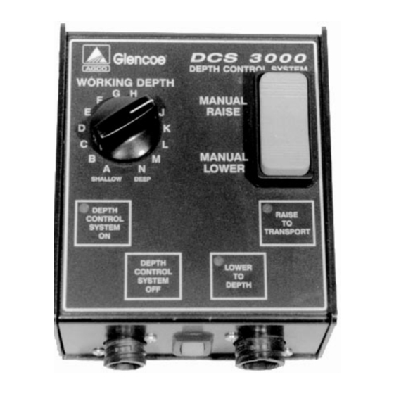
- Page 5 INTRODUCTION DCS-1 ® Fig. 1 - Glencoe DCS3000 Depth Control Monitor The Glencoe(r) Depth Control System DCS3000 gives fingertip single point depth control of towed implements using state of the art agricultural electronics. The system allows quick and easy adjustment of implement working depth from the operator’s seat.
- Page 6 After the DCS installation is completed, purge air as described later. authorized Glencoe(r) dealer or AGCO Corp. • Do not allow anyone to operate implement until TRACTOR REQUIREMENTS after reading this manual and understanding safety and operation of this machine.
-
Page 7: Operation
OPERATION BEFORE USE: Hose Connections to Tractor Before using the DCS, whether for the first time Connect the lift cylinder hoses to the tractor outlets when new, or for the season: (Fig. 3) as follows: - Hose from Port T-1 (side of valve block) to 1. -
Page 8: Switch Functions
OPERATION DCS-1A Fig. 4 - Control Monitor Switches and LED’s 1. Light Emitting Diodes 2. Rocker Switch SWITCH FUNCTIONS Note: Manual switch overrides and disengages Automatic Mode. After using manual switch, press Depth Control System On and release Depth Control ON to return to automatic mode. -
Page 9: Operating Modes And Calibration
OPERATION OPERATING MODES General Error Mode The depth control system has three operating The error mode is automatically entered when an modes: apparent problem exists as identified by the monitor program. - Manual mode When in error mode, the LED’s flash individually or - Automatic mode in multiples at a rate of two per second. - Page 10 OPERATION MONITOR TROUBLESHOOTING Problem Probable Cause Probable Correction ON LED Flashing Monitor program “locked up” Temporary program problem Turn monitor OFF then ON again to clear error mode. Faulty monitor Electronic circuit failure Press OFF and ON switches more than once.
-
Page 11: Maintenance
MAINTENANCE PURGING AIR FROM LIFT SYSTEM ELECTRIC CURRENT DRAW IMPORTANT! Cylinder operation will be very erratic Standard Valve Block and uneven until all air is purged from main lift A small amount of current is continuously drawn by circuit. the monitor, whether or not it is in active use. Note: Also see pp. -
Page 12: Care And Maintenance
MAINTENANCE CARE AND MAINTENANCE SENSOR ADJUSTMENT 1, Fully raise implement, stop tractor engine, set • Always keep the monitor dry. In most cases, the brakes and shift to park position. tractor cab provides sufficient protection. IMPORTANT! Monitor is not watertight and must 2. -
Page 13: Installation
INSTALLATION ASSEMBLY SAFETY BEFORE DELIVERY CAUTION! TO AVOID PERSONAL INJURY, • After completing assembly of machine, be sure READ, UNDERSTAND AND FOLLOW all nuts, bolts, other fasteners, and hydraulic THE SAFETY INFORMATION fittings are properly tightened. BELOW. • Be sure all safety guards and safety locking devices are in place. -
Page 14: Depth Position Sensor
INSTALLATION INTRODUCTION DEPTH POSITION SENSOR These instructions are for installing the DCS3000 Either a plain rod-type (Fig. 1) or roller-type (Fig. 2) Depth Control System on the following Glencoe® crank is used for the sensor mechanism. For either tillage implements: crank: UM4650 FC3500... - Page 15 INSTALLATION DCS-7A DCS-8A Fig. 3 - Sensor Assembly Fig. 4 - Sensor Mounting Bracket 1. Shield (All Models) - Secondary Tillage 2. Mounting Bracket (CC4450) SENSOR MOUNTING BRACKETS 1. With correct mounting bracket (Figs. 3-6), attach sensor and crank assembly to bracket with 5/16”...
- Page 16 INSTALLATION CC4450 MODELS Fig. 7 - Component Locations 1. Sensor 2. Actuator 3. Valve Block SS7400 MODELS Fig. 8 - Component Locations 1. Sensor 2. Actuator 3. Valve Block...
- Page 17 INSTALLATION SECONDARY TILLAGE MODELS Fig. 9 - Component Locations 1. Sensor 2. Actuator 3. Valve Block DR8600 MODELS Fig. 10 - Component Locations 1. Sensor 2. Actuator 3. Valve Block...
-
Page 18: Actuator Arm
INSTALLATION DCS-15A DCS-16A Fig. 11 - Actuator Arm for Secondary Tillage Fig. 12 - Actuator Arm for CC4450 ACTUATOR ARM Installation and Adjustment IMPORTANT! Temporarily install arm away from sensor crank. Perform final positioning and adjustment (p. 8) after installation is completed and hydraulic system is charged and purged of air (p. -
Page 19: Hydraulic Valve Block
INSTALLATION HYDRAULIC VALVE BLOCK 1. If required, install extra solenoid valve in valve block for open-center tractor hydraulic systems (see below). 2. Attach valve mounting brackets and shield to valve block with two 5/16” x 4-1/2” bolts, lock washers, and nuts (Fig. 15). 3. -
Page 20: Hydraulic Connections
INSTALLATION DURING IMPLEMENT SETUP AFTER IMPLEMENT SETUP 1. Review these instructions and appropriate Use the instructions and diagram on the following diagram on following pages before installing pages for the appropriate implement. basic implement hydraulic system. HYDRAULIC CONNECTIONS Note: Callouts in diagrams are for additional parts and hoses supplied in bundle. - Page 21 INSTALLATION HYDRAULIC SCHEMATIC - Rigid Models, CC 4450 Fig. 20 - Schematic for Rigid Frame CC4450 1. Hoses, 48” 2. Valve Block 3. Elbow, 90 HYDRAULIC SCHEMATIC - Folding Wing Models, CC4450 Fig. 21 - Schematic for Folding Wing CC4450 1.
- Page 22 INSTALLATION HYDRAULIC CONNECTIONS Rigid Models - SS7400 (Fig. 22) 1. With valve block securely mounted on frame, install three straight fittings in valve block. Install angle fitting in Port T1. 2. Disconnect existing hose from base end of cylinder and reconnect to Port T1 (pressure). 3.
- Page 23 INSTALLATION HYDRAULIC SCHEMATIC - Rigid Models, SS7400 Fig. 22 - Schematic for Rigid Frame SS7400 1. Hoses, 48” 2. Valve Block 3. Elbow, 90 HYDRAULIC SCHEMATIC - Folding Wing Models, SS7400 Fig. 23 - Schematic for Folding Wing SS7400 1. Hoses, 48” 2.
- Page 24 HYDRAULIC CONNECTIONS Secondary Tillage Models (Fig. 24) Note: The following models are considered secondary tillage implements: UM4650 SF4500 FC3500 UM6000 SF4600 FC3550 SS7400 FC3600 1. With valve block securely mounted on frame, install four straight fittings in valve block. Note: If bundle includes an angle, install in Port 2.
- Page 25 INSTALLATION HYDRAULIC SCHEMATIC - Secondary Tillage Implements Fig. 24 - Schematic for Secondary Tillage Implements with Two, Four, Six Lift Cylinders 1. Hoses, 48” 2. Valve Block 3. Elbow, 90 HYDRAULIC SCHEMATIC - DR8600 Fig. 25 - Schematic for DR8600 1.
-
Page 26: Wire Harness
INSTALLATION MAIN WIRE HARNESS Note: Also refer to next page for schematic. 1. Starting at valve block, lay harness on frame toward the front of machine. 2. Connect position sensor plug to three-prong sensor connector on harness (Fig. 26). Note: Use slot in top of shield for harness wire. 3. - Page 27 INSTALLATION WIRING SCHEMATIC - All Models Fig. 29 - Schematic for DCS 3000...
-
Page 28: Lift Cylinder Link (Cc4450) And Final Adjustments
INSTALLATION LIFT CYLINDER LINK - CC4450 Only A “loose link” connects the rod end of the center lift cylinder to the frame. While the design allows ease removal of the cylinder for other uses, link movement must stop when using the DCS3000 Depth Control System. -
Page 29: Purging Air From Hydraulic System
INSTALLATION HYDRAULIC SYSTEM - General Wing Fold Circuit The main lift cylinders on wing fold models are 1. With rod ends of wing fold cylinders connected in a series circuit. Each cylinder has a disconnected, slowly extend and retract different diameter, with the smaller called a “slave” cylinders. -
Page 30: Cylinder Strokeand Charging The Hydraulic System
INSTALLATION CYLINDER STROKE CHARGING THE HYDRAULIC SYSTEM Manual Fill Method If the hydraulic lift system is fully charged with no air in the system and the implement is still not level IMPORTANT! Cylinder sizes must be in positions when raised, check the cylinder stroke. shown in individual implement assembly instructions for proper system operation. -
Page 31: Special Torque Values
INSTALLATION SPECIAL TORQUE VALUES IMPORTANT! Over-tightening straight-thread hydraulic fittings damages sealing surfaces of JIC fittings and damages o-rings on adapter fittings. Note: Do not use pipe sealant or Teflon© tape on threads. JIC 37 Flare Adapter Fittings, Adapter-to-Tube 1/4” tube or hose: 12 ft-lb (16 N⋅m)* 3/8”... - Page 35 METRIC/U.S. CUSTOMARY UNIT EQUIVALENTS MULTIPLY: to get: MULTIPLY to get: LINEAR inches x 25.4 = millimeters (mm) x 0.03937 inches feet x 0.3048 = meters (m) x 1.0936 feet yards x 0.9144 = meters (m) x 1.0936 yards miles x 1.6093 = kilometers (km) x 0.6214 miles...
- Page 36 Glencoe ® AGCO CORPORATION 4205 River Green Parkway Duluth, Georgia 30096 Printed in U.S.A.
Need help?
Do you have a question about the Glencoe DCS3000 and is the answer not in the manual?
Questions and answers