Table of Contents

Summary of Contents for 2easy CDV-DBC4R
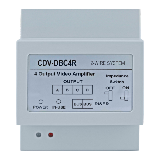
- Page 1 CDV-DBC4R Riser Distributor User Manual DBC4R IN-USE POWER Please read this manual carefully before using this product , keep it safe for future use. We reserve the right to modify the specification in this manual at any time without notice.
-
Page 2: Parts And Functions
1. Description The DBC4R is a 4 output video amplifier. • There are 2 working modes: riser mode and distributor mode; • Separate isolation protection without affecting another devices on bus system; • Short-circuit indication for convenient maintenance; • Periodic self-detection mechanism for recovery. 2. -
Page 3: Unit Mounting
DIP Switch: please see below for the DIP settings: DIP1 operates in riser mode operates in distributor mode DIP2 Reserved Default DIP3 Gain High Gain Auto Note: • Operation mode: Protection mode will be activated once its connected devices are short circuited, and power supply for ABCD outputs will be turn off, the flashing in- use indicator shows the distributor is in protection mode. - Page 4 4. System Wiring with DBC4R 1.Basic IN-OUT expansion wiring(distributor mode) Cable Usage Cable Usage Twisted cable 2x0.75 mm Twisted cable 2x1 mm Twisted cable 2x1 mm Twisted cable 2x1.5 mm PC6A DBC4R Wiring diagram: Max.4 DBC4R 100~240VAC PC6A BUS(IM) BUS(DS) DIP1->OFF * Max.8 monitors can be connected for every DBC4R.
- Page 5 2.Multi risers wiring(riser mode) Cable Usage Cable Usage Twisted cable 2x0.75 mm Twisted cable 2x1 mm Twisted cable 2x1 mm Twisted cable 2x1.5 mm Type 1 Max.8 DBC4R PC6A Max.4 risers...
-
Page 6: Wiring Diagram
Wiring diagram: A B C D A B C D DBC4R DBC4R to next branch distributor to next branch distributor Max.4 risers 100~240VAC A B C D PC6A DBC4R DIP1->ON BUS(IM) BUS(DS) Type 2 DBC4R to next DBC4R PC6A... - Page 7 Wiring diagram: A B C D A B C D DBC4R DBC4R to next branch distributor to next branch distributor 100~240VAC A B C D A B C D PC6A DBC4R DBC4R DIP1->ON BUS(IM) BUS(DS) to next DBC4R * The DIP1 should set to “ON” for all DBC4R.
- Page 8 3.Multi monitors wiring(distributor mode) PC6A DBC4R Wiring diagram: OFF ON Impedance DIP1->OFF switch->ON * The impedance switch should set to “ON” for the last DBC4R at the end of the bus. OFF ON Impedance DIP1->OFF switch->OFF 100~240VAC PC6A BUS(IM) BUS(DS)
-
Page 9: Specification
5. Specification Power Supply : DC20~30V Working Temperature: C~+40 Wiring: 2 wires (non-polarity) Dimension: 89(H)×71(W)×45(D)mm Standby Current: 4~5mA The design and specifications can be changed without notice to the user. Right to interpret and copyright of this manual are preserved. DT-ENG-DBC4R-V1 20180531...
Need help?
Do you have a question about the CDV-DBC4R and is the answer not in the manual?
Questions and answers