Table of Contents
Advertisement
Quick Links
Advertisement
Table of Contents

Summary of Contents for Bancolini UNISCAN C6R
- Page 2 Codice/Code 0000010800 – Revisione/Release 1.00 – settembre 2004...
-
Page 7: Table Of Contents
Contents About This Guide Introduction ..............xi Chapter Descriptions . - Page 8 Scanning in the Hands-Free Mode ..........2-10 Chapter 3.
- Page 9 Contents Chapter 6. RS-232 Interface Introduction ..............6-1 Connecting an RS-232 Interface .
- Page 10 IBM Default Parameters ............8-3 IBM 468X/469X Host Parameters .
- Page 11 Contents Chapter 12. Symbologies Introduction ..............12-1 Scanning Sequence Examples .
- Page 12 Enable/Disable Interleaved 2 of 5 ..........12-48 Set Lengths for Interleaved 2 of 5 .
- Page 13 Contents Synapse Interface............13-11 Chapter 14.
- Page 14 Appendix C. Sample Bar Codes Code 39 ..............C-1 UPC/EAN .
-
Page 15: About This Guide
About This Guide Introduction The Uniscan C6R Product Reference Guide provides general instructions for setting up, operating, maintaining and troubleshooting the Uniscan C6R. Chapter Descriptions • Chapter 1, Getting Started provides a product overview and unpacking instructions. • Chapter 2, Scanning describes parts of the scanner, beeper and LED definitions, how to use the scanner in hand-held and hands-free modes. - Page 16 • Chapter 9, Wand Emulation Interface covers all information for setting up your scanner for Wand emulation operation. • Chapter 10, Undecoded Scanner Emulation Interface covers information for setting up your scanner for Undecoded Scanner emulation operation. • Chapter 11, 123Scan (PC based scanner configuration tool) provides the bar code you must scan to communicate with the 123Scan program.
-
Page 17: Notational Conventions
Baud Rate 9600 Indicates Default Feature/Option Related Publications The Uniscan C6R Quick Reference Guide, provides general information to help the user get started with the scanner. It includes basic set-up and operation instructions. Service Information If you have a problem with your equipment, contact the... - Page 18 If your problem cannot be solved over the phone, you may need to return your equipment for servicing. If that is necessary, you will be given specific directions. Note: A Bancolini Symbol is not responsible for any damages incurred during shipment if the approved shipping container is not used. Shipping the units...
-
Page 19: Chapter 1. Getting Started
Getting Started Introduction The Uniscan C6R scanner combines excellent scanning performance and advanced ergonomics to provide the best value in a lightweight laser scanner. Whether used as a hand-held scanner or in hands-free mode in a stand, the scanner ensures comfort and ease of use for extended periods of time. -
Page 20: Unpacking Your Scanner
• Keyboard Wedge connection to a host. Scanned data is interpreted by your host as keystrokes. • International Keyboards supported: North America, German, French, French International, Spanish, Italian, Swedish, British, Japanese, and Portuguese- Brazilian. • Wand Emulation connection to a host. The scanner is connected to a portable data terminal, a controller, or host which collects the data as wand data and decodes it. -
Page 21: Setting Up The Scanner
Getting Started Setting Up the Scanner Installing the Interface Cable 1. Plug the interface cable modular connector into the cable interface port on the bottom of the scanner handle. (See Figure 1-2.) 2. Gently tug the cable to ensure the connector is properly secured. 3. -
Page 22: Connecting Power (If Required)
Connecting Power (if required) If your host does not provide power to the scanner, you will need an external power connection to the scanner: 1. Connect the interface cable to the bottom of the scanner, as described in Installing the Interface Cable on page 1-3. -
Page 23: Connecting A Synapse Cable Interface
Getting Started Connecting a Synapse Cable Interface Note: See the Synapse Interface Guide provided with your Synapse cable for detailed setup instructions. Synapse Smart Cables enable interfacing to a variety of hosts. The appropriate Synapse cable has the built-in intelligence to detect the host to which it is connected. To host Synapse adapter cable Synapse Smart Cable... -
Page 25: Chapter 2. Scanning
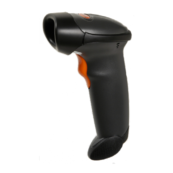
Chapter 2 Scanning Introduction This chapter covers the techniques involved in scanning bar codes, beeper and LED definitions, and general instructions and tips about scanning. Beeper Exit Window Trigger Figure 2-1. Scanner Parts... -
Page 26: Beeper Definitions
Beeper Definitions The scanner communicates with the user by emitting different beeper sequences and patterns. Table 2-1 defines beep sequences that occur during both normal scanning and while programming the scanner. Table 2-1. Standard Beeper Definitions Beeper Sequence Indication Standard Use Low/medium/high beep Power up. - Page 27 Scanning Table 2-1. Standard Beeper Definitions (Continued) Beeper Sequence Indication Lo/hi/lo beep The Code 39 buffer was erased or there was an attempt to clear or transmit an empty buffer. Lo/hi beep A successful transmission of buffered data. Host Specific USB only 4 short high beeps Scanner has not completed initialization.
-
Page 28: Led Definitions
LED Definitions In addition to beeper sequences, the scanner communicates with the user using a two-color LED display. Table 2-2 defines LED colors that display during scanning. Table 2-2. Standard LED Definitions Indication No power is applied to the scanner, or the scanner is on and ready to scan. -
Page 29: Scanning In Hand-Held Mode
Scanning Scanning in Hand-Held Mode Install and program your scanner. (Refer to each host chapter and Chapter 4, User Preferences, Chapter 12, Symbologies, Chapter 13, Miscellaneous Scanner Options, and Chapter 14, Advanced Data Formatting for instructions on programming your scanner.) Figure 2-2. -
Page 30: Aiming
Aiming Do not hold the scanner directly over the bar code. Laser light reflecting directly back into the scanner from the bar code is known as specular reflection. This specular reflection can make decoding difficult. You can tilt the scanner up to 55° forward or back and achieve a successful decode (Figure 2-3). -
Page 31: Decode Zone
6" 2.5" 7.5 mil 1.5" 10.0" 25.4 10 mil 1.0" 14.5" 100% UPC 17.0" 20 mil 23.0" 12.7 25.4 38.1 50.8 63.5 Depth of Field *Minimum distance determined by symbol length and scan angle Figure 2-4. Uniscan C6R Decode Zone... -
Page 32: Scanning In Hands-Free Mode
Scanning in Hands-Free Mode The C6R Intellistand adds greater flexibility to your scanning operation. Refer to Assembling the Stand, Mounting the Stand (optional), and Scanning in the Hands-Free Mode for detailed information about hands-free scanning. Assembling the Stand 1. Unscrew the wingnut from the bottom of the One piece scanner one piece scanner... -
Page 33: Mounting The Stand (Optional)
Scanning Mounting the Stand (optional) You can attach the base of the scanner’s stand to a flat surface using two screws or double- sided tape (not provided). Two screw-mount holes. Double-sided tape areas (3 places) Figure 2-6. Mounting the Stand Screw Mount 1. -
Page 34: Scanning In Hands-Free Mode
Scanning in Hands-Free Mode The optional Intellistand adds greater flexibility to your scanning operation. Scanning in the Hands-Free Mode When the scanner is seated in the stand’s “cup”, the scanner’s built-in sensor places the scanner in hands-free mode. When the scanner is removed from the stand it operates in its normal hand-held mode. -
Page 35: Chapter 3. Maintenance And Technical Specifications
Chapter 3 Maintenance and Technical Specifications Introduction This chapter covers suggested scanner maintenance, troubleshooting, technical specifications, and signal descriptions (pinouts). Maintenance Cleaning the exit window is the only maintenance required. A dirty window may affect scanning accuracy. • Do not allow any abrasive material to touch the window •... -
Page 36: Troubleshooting
Troubleshooting Table 3-1. Troubleshooting Problem Possible Causes Possible Solutions Nothing happens when No power to the scanner. Check the system power. Ensure the you follow the operating power supply is connected if your instructions, or the configuration requires a power supply. scanner displays erratic behavior (laser does not come on, scanner emits... - Page 37 Maintenance and Technical Specifications Table 3-1. Troubleshooting (Continued) Problem Possible Causes Possible Solutions Scanned data is Scanner is not programmed to Be sure proper host is selected. (See the incorrectly displayed on work with the host. Check host chapter for your scanner.) the host.
-
Page 38: Technical Specifications
Technical Specifications Table 3-2. Technical Specifications Item Description Power Requirements Decoded: 5 VDC + / - 10% @ approximately 200mA (nominal) Stand-By Current 500mA (max) Power Source Depending on host: • Host powered • External power supply • Battery box: Converts a 9 Volt battery to a 5 Volt battery Decode Capability Decoded:... - Page 39 Maintenance and Technical Specifications Table 3-2. Technical Specifications (Continued) Item Description Storage Temperature -40° to 140° F (-40° to 60° C) Humidity 5% to 95% (non-condensing) Weight (without cable) 5.15 oz. (146 g) Dimensions: Height 6.0 in. (15.2 cm) Width 2.5in.
-
Page 40: Scanner Signal Descriptions
Scanner Signal Descriptions Bottom of scanner Cable interface port PIN 10 PIN 1 Interface cable modular connector Figure 3-1. Scanner Cable Pinouts... - Page 41 Maintenance and Technical Specifications The signal descriptions in Table 3-3 apply to the connector on the scanner and are for reference only. Table 3-3. Scanner Signal Pin-outs UNISCAN C6R Keyboard Synapse RS-232 Wedge Wand Reserved SynClock Reserved Reserved Reserved Jump to Pin 6...
-
Page 43: Chapter 4. User Preferences
User Preferences Introduction You have the option to program the UNISCAN C6R to perform various functions, or activate different features. This chapter describes each user preference feature and provides the programming bar codes necessary for selecting these features for your C6R scanner. -
Page 44: Scanning Sequence Examples
If you are not using a Synapse or USB cable you must select a host type (see each host chapter for specific host information). After you hear the power-up beeps, select a host type. This only needs to be done once, upon the first power-up when connected to a new host. -
Page 45: User Preferences Default Parameters
User Preferences User Preferences Default Parameters Table 4-1 lists the defaults for user preferences parameters. If you wish to change any option, scan the appropriate bar code(s) provided in the User Preferences section beginning on page 4-4. Note: See Appendix A, Standard Default Parameters for all user preferences, hosts, symbologies, and miscellaneous default parameters. -
Page 46: User Preferences
User Preferences Set Default Parameter Scanning this bar code returns all parameters to the default values listed in Table A-1 on page A-1. Set All Defaults... -
Page 47: Beeper Tone
User Preferences Beeper Tone To select a decode beep frequency (tone), scan the Low Frequency, Medium Frequency, or High Frequency bar code. Low Frequency Medium Frequency (Optimum Settings) High Frequency... -
Page 48: Beeper Volume
Beeper Volume To select a beeper volume, scan the Low Volume, Medium Volume, or High Volume bar code. Low Volume Medium Volume High Volume... -
Page 49: Power Mode
User Preferences Power Mode This parameter determines whether or not power remains on after a decode attempt. When in reduced power mode, the scanner enters into a low power consumption mode to preserve battery life after each decode attempt. When in continuous power mode, power remains on after each decode attempt. -
Page 50: Laser On Time
Laser On Time This parameter sets the maximum time that decode processing continues during a scan attempt. It is programmable in 0.1 second increments from 0.5 to 9.9 seconds. The default Laser On Time is 3.0 seconds. To set a Laser On Time, scan the bar code below. Next, scan two numeric bar codes beginning on page Appendix D that correspond to the desired on time. -
Page 51: Beep After Good Decode
User Preferences Beep After Good Decode Scan a bar code below to select whether or not the scanner beeps after a good decode. If Do Not Beep After Good Decode is selected, the beeper still operates during parameter menu scanning and indicates error conditions. Beep After Good Decode (Enable) Do Not Beep After Good Decode... - Page 52 4-10...
-
Page 53: Chapter 5. Keyboard Wedge Interface
Chapter 5 Keyboard Wedge Interface Introduction This chapter covers Keyboard Wedge interface information for setting up your scanner. This interface type is used to attach the scanner between the keyboard and host computer. The scanner translates the bar code data into keystrokes. The host computer accepts the keystrokes as if they originate from the keyboard. -
Page 54: Connecting A Keyboard Wedge Interface
Connecting a Keyboard Wedge Interface Male DIN Keyboard Connector to Host Connector to Host Y-cable Power supply (if needed) Figure 5-1. Keyboard Wedge Connection with Y-cable To connect the Keyboard Wedge Y-cable: 1. Switch off the host and unplug the keyboard connector. 2. -
Page 55: Keyboard Wedge Default Parameters
Keyboard Wedge Interface Keyboard Wedge Default Parameters Table 5-1 lists the defaults for Keyboard Wedge host parameters. If you wish to change any option, scan the appropriate bar code(s) provided in the Keyboard Wedge Host Parameters section beginning on page 5-4. Note: See Appendix A, Standard Default Parameters for all user... -
Page 56: Keyboard Wedge Host Types
Keyboard Wedge Host Types Keyboard Wedge Host Types Select your keyboard wedge host by scanning one of the bar codes below. IBM PC/AT & IBM PC Compatibles IBM PS/2 (Model 30) IBM AT NOTEBOOK IBM XT NCR 7052 Note: User selection is required to configure this interface and this is the most common selection. -
Page 57: Keyboard Wedge Country Types (Country Codes)
Keyboard Wedge Interface Keyboard Wedge Country Types (Country Codes) Scan the bar code corresponding to your keyboard type. If your particular keyboard type is not listed, see Alternate Numeric Keypad Emulation on page 5-10. North American German Windows French Windows... - Page 58 French Canadian Windows 95/98 French Canadian Windows XP/2000...
- Page 59 Keyboard Wedge Interface Keyboard Wedge Country Types (continued) Spanish Windows Italian Windows Swedish Windows UK English Windows Japanese Windows...
-
Page 60: Ignore Unknown Characters
Keyboard Wedge Country Types (continued) Portuguese-Brazilian Windows Ignore Unknown Characters Unknown characters are characters the host does not recognize. When Send Bar Codes With Unknown Characters is selected, all bar code data is sent except for unknown characters, and no error beeps sound on the scanner. When Do Not Send Bar Codes With Unknown Characters is selected, bar code data is sent up to the first unknown character and then an error beep will sound on the scanner. -
Page 61: Keystroke Delay
Keyboard Wedge Interface Keystroke Delay This is the delay in milliseconds between emulated keystrokes. Scan a bar code below to increase the delay when hosts require a slower transmission of data. No Delay Medium Delay (20 msec) Long Delay (40 msec) -
Page 62: Intra-Keystroke Delay
Intra-Keystroke Delay When enabled, an additional delay is inserted between each emulated key depression and release. This sets the Keystroke Delay parameter to a minimum of 5 msec as well. Enable Disable Alternate Numeric Keypad Emulation This allows emulation of most other country keyboard types not listed in Keyboard Wedge Country Types (Country Codes) on page 5-5 in a Microsoft operating system environment. -
Page 63: Caps Lock On
Keyboard Wedge Interface Caps Lock On When enabled, the scanner emulates keystrokes as if the Caps Lock key is always pressed. Enable Caps Lock On Disable Caps Lock On 5-11... -
Page 64: Caps Lock Override
Caps Lock Override When enabled, on AT or AT Notebook hosts, the keyboard ignores the state of the Caps Lock key. Therefore, an ‘A’ in the bar code is sent as an ‘A’ no matter what the state of the keyboard’s Caps Lock key. -
Page 65: Function Key Mapping
Keyboard Wedge Interface Convert to Lower Case No Convert Function Key Mapping ASCII values under 32 are normally sent as control key sequences (see Table 5-2 on page 5-18). When this parameter is enabled, the keys in bold are sent in place of the standard key mapping. -
Page 66: Fn1 Substitution
FN1 Substitution When enabled, this parameter allows replacement of any FN1 characters in an EAN128 bar code with a keystroke chosen by the user.(see FN1 Substitution Values on page 13-9). Enable *Disable Send Make and Break When enabled, the scan codes for releasing a key are not sent. *Send Make and Break Scan Codes Send Make Scan Code Only 5-14... -
Page 67: Keyboard Maps
Keyboard Wedge Interface Keyboard Maps The following keyboard maps are provided for prefix/suffix keystroke parameters. To program the prefix/suffix values, see the bar codes on page 13-5. 7006 7014 5001 5002 5003 5004 5005 5006 5007 5008 5009 5010 5011 5012 7010 7007... - Page 68 5001 7008 5002 7014 7009 5003 7012 7003 5004 7013 5005 5006 5007 7004 5008 5009 5010 7011 7002 Figure 5-4. IBM PC/AT 5002 1045 5013 5001 5011 5003 5004 5014 5015 5005 5006 1043 5016 5007 5018 5008 5017 7013 5019 5009...
- Page 69 Keyboard Wedge Interface 1068 1067 1065 1066 1069 1070 1071 1075 1072 1073 1074 1076 1077 1078 1079 1080 1082 1083 1084 1085 1081 5002 1045 5013 1086 5001 5011 5003 5014 5015 1087 5004 5005 5006 1043 5016 1088 5007 5018 1089...
-
Page 70: Ascii Character Set
ASCII Character Set Note: Code 39 Full ASCII interprets the bar code special character ($ + % /) preceding a Code 39 character and assigns an ASCII character value to the pair. For example, when Code 39 Full ASCII is enabled and a +B is scanned, it is interpreted as b, %J as ?, and %V as @. - Page 71 Keyboard Wedge Interface Table 5-2. Keyboard Wedge ASCII Character Set (Continued) 1015 CTRL O 1016 CTRL P 1017 CTRL Q 1018 CTRL R 1019 CTRL S 1020 CTRL T 1021 CTRL U 1022 CTRL V 1023 CTRL W 1024 CTRL X 1025 CTRL Y 1026...
- Page 72 Table 5-2. Keyboard Wedge ASCII Character Set (Continued) 1042 1043 1044 1045 1046 1047 1048 1049 1050 1051 1052 1053 1054 1055 1056 1057 1058 1059 1060 < 1061 1062 > 1063 1064 1065 1066 1067 1068 5-20...
- Page 73 Keyboard Wedge Interface Table 5-2. Keyboard Wedge ASCII Character Set (Continued) 1069 1070 1071 1072 1073 1074 1075 1076 1077 1078 1079 1080 1081 1082 1083 1084 1085 1086 1087 1088 1089 1090 1091 1092 1093 1094 1095 5-21...
- Page 74 Table 5-2. Keyboard Wedge ASCII Character Set (Continued) 1096 ‘ 1097 1098 1099 1100 1101 1102 1103 1104 1105 1106 1107 1108 1109 1110 1111 1112 1113 1114 1115 1116 1117 1118 1119 1120 1121 1122 5-22...
- Page 75 Keyboard Wedge Interface Table 5-2. Keyboard Wedge ASCII Character Set (Continued) 1123 1124 1125 1126 ALT Keys Keystroke 2065 ALT A 2066 ALT B 2067 ALT C 2068 ALT D 2069 ALT E 2070 ALT F 2071 ALT G 2072 ALT H 2073 ALT I...
- Page 76 Table 5-2. Keyboard Wedge ASCII Character Set (Continued) 2087 ALT W 2088 ALT X 2089 ALT Y 2090 ALT Z GUI Keys Keystrokes 3000 Right Control Key 3048 GUI 0 3049 GUI 1 3050 GUI 2 3051 GUI 3 3052 GUI 4 3053 GUI 5...
- Page 77 Keyboard Wedge Interface Table 5-2. Keyboard Wedge ASCII Character Set (Continued) 3076 GUI L 3077 GUI M 3078 GUI N 3079 GUI O 3080 GUI P 3081 GUI Q 3082 GUI R 3083 GUI S 3084 GUI T 3085 GUI U 3086 GUI V 3087...
- Page 78 Table 5-2. Keyboard Wedge ASCII Character Set (Continued) 5012 5013 5014 5015 5016 5017 5018 5019 5020 5021 5022 5023 5024 Numeric Keypad Keystroke 6042 6043 6044 undefined 6045 6046 6047 6048 6049 6050 6051 6052 6053 6054 5-26...
- Page 79 Keyboard Wedge Interface Table 5-2. Keyboard Wedge ASCII Character Set (Continued) 6055 6056 6057 6058 Enter 6059 Num Lock Extended Keypad Keystroke 7001 Break 7002 Delete 7003 Pg Up 7004 7005 Pg Dn 7006 Pause 7007 Scroll Lock 7008 Backspace 7009 7010 Print Screen...
- Page 80 5-28...
-
Page 81: Introduction
Chapter 6 RS-232 Interface Introduction This chapter covers RS-232 host information for setting up your scanner. The RS-232 interface is used to attach the scanner to point-of-sale devices, host computers, or other devices with an available RS-232 port (e.g., com port). If your particular host is not listed in Table 6-2, you need to set the communication... -
Page 82: Connecting An Rs-232 Interface
Throughout the programming bar code menus, default values are indicated with asterisks Baud Rate 9600 Feature/Option Indicates Default Connecting an RS-232 Interface This connection is made directly from the scanner to the host computer. Serial Port Connector to Host Power supply cable Interface cable Interface cable Power supply... -
Page 83: Rs-232 Default Parameters
RS-232 Interface RS-232 Default Parameters Table 6-1 lists the defaults for RS-232 host parameters. If you wish to change any option, scan the appropriate bar code(s) provided in the Parameter Descriptions section beginning on page 6-5. Note: See Appendix A, Standard Default Parameters for all user preferences, hosts, symbologies, and miscellaneous default parameters. - Page 84 Table 6-1. RS-232 Host Default Table (Continued) Page Parameter Default Number Ignore Unknown Characters Send Bar Code 6-24 User selection is required to configure this interface and this is the most common selection.
-
Page 85: Host Parameters
RS-232 Interface RS-232 Host Parameters Various RS-232 hosts are set up with their own parameter default settings (Table 6-2). Selecting the ICL, Fujitsu, Wincor-Nixdorf Mode A, Wincor-Nixdorf Mode B, Olivetti, Omron, or terminal sets the defaults listed below. Table 6-2. Terminal Specific RS-232 Wincor- Wincor- Nixdorf... - Page 86 RS-232 Host Parameters (continued) Selecting the ICL, Fujitsu, Wincor-Nixdorf Mode A, Wincor-Nixdorf Mode B, OPOS terminal enables the transmission of code ID characters listed in Table 6-3 below. These code ID characters are not programmable and are separate from the Transmit Code ID feature. The Transmit Code ID feature should not be enabled for these terminals.
-
Page 87: Host Types
RS-232 Interface RS-232 Host Types To select an RS-232 host interface, scan one of the following bar codes. Standard RS-232 ICL RS-232 Wincor-Nixdorf RS-232 Mode A Wincor-Nixdorf RS-232 Mode B Olivetti ORS4500... - Page 88 Omron OPOS/JPOS Fujitsu RS-232 Note: 1 User selection is required to configure this interface and this is the most common selection.
-
Page 89: Baud Rate
RS-232 Interface Baud Rate Baud rate is the number of bits of data transmitted per second. The scanner's baud rate setting should match the baud rate setting of the host device. If not, data may not reach the host device or may reach it in distorted form. Baud Rate 600 Baud Rate 1200 Baud Rate 2400... - Page 90 Baud Rate (continued) Baud Rate 9600 Baud Rate 19,200 Baud Rate 38,400 6-10...
-
Page 91: Parity
RS-232 Interface Parity A parity check bit is the most significant bit of each ASCII coded character. Select the parity type according to host device requirements. Select Odd parity and the parity bit value is set to 0 or 1, based on data, to ensure that an odd number of 1 bits are contained in the coded character. - Page 92 Parity (continued) Select Space parity and the parity bit is always 0. Space Select None when no parity bit is required. None 6-12...
-
Page 93: Stop Bit Select
RS-232 Interface Stop Bit Select The stop bit(s) at the end of each transmitted character marks the end of transmission of one character and prepares the receiving device for the next character in the serial data stream. The number of stop bits selected (one or two) depends on the number the receiving terminal is programmed to accommodate. -
Page 94: Check Receive Errors
Check Receive Errors Select whether or not the parity, framing, and overrun of received characters are checked. The parity value of received characters is verified against the parity parameter selected above. Check For Received Errors Do Not Check For Received Errors 6-14... -
Page 95: Hardware Handshaking
RS-232 Interface Hardware Handshaking The data interface consists of an RS-232 port designed to operate either with or without the hardware handshaking lines, Request to Send (RTS), and Clear to Send (CTS). If Standard RTS/CTS handshaking is not selected, scan data is transmitted as it becomes available. - Page 96 None Scan the bar code below if no Hardware Handshaking is desired. None Standard RTS/CTS Scan the bar code below to select Standard RTS/CTS Hardware Handshaking. Standard RTS/CTS RTS/CTS Option 1 When RTS/CTS Option 1 is selected, the scanner asserts RTS before transmitting and ignores the state of CTS.
-
Page 97: Software Handshaking
RS-232 Interface RTS/CTS Option 3 When Option 3 is selected, the scanner asserts RTS prior to any data transmission, regardless of the state of CTS. The scanner waits up to Host Serial Response Time-out (default) for CTS to be asserted. If CTS is not asserted during this time, the scanner issues an error indication and discards the data. - Page 98 ACK/NAK When this option is selected, after transmitting data, the scanner expects either an ACK or NAK response from the host. When a NAK is received, the scanner transmits the same data again and waits for either an ACK or NAK. After three unsuccessful attempts to send data when NAKs are received, the scanner issues an error indication and discards the data.
- Page 99 RS-232 Interface ACK/NAK with ENQ This combines the two previous options. For re-transmissions of data, due to a NAK from the host, an additional ENQ is not required. ACK/NAK with ENQ XON/XOFF An XOFF character turns the scanner transmission off until the scanner receives an XON character.
-
Page 100: Host Serial Response Time-Out
Host Serial Response Time-out This parameter specifies how long the scanner waits for an ACK, NAK, or CTS before determining that a transmission error has occurred. This only applies when in one of the ACK/NAK Software Handshaking modes, or RTS/CTS Hardware Handshaking option. Minimum: 2 Sec Low: 2.5 Sec Medium: 5 Sec... -
Page 101: Rts Line State
RS-232 Interface RTS Line State This parameter sets the idle state of the Serial Host RTS line. Scan a bar code below to select Low RTS or High RTS line state. Host: Low RTS Host: High RTS Beep on <BEL> When this parameter is enabled, the scanner issues a beep when a <BEL>... -
Page 102: Intercharacter Delay
Intercharacter Delay This parameter specifies the intercharacter delay inserted between character transmissions. Minimum: 0 msec Low: 25 msec Medium: 50 msec High: 75 msec Maximum: 99 msec 6-22... -
Page 103: Nixdorf Beep/Led Options
RS-232 Interface Nixdorf Beep/LED Options When Nixdorf Mode B is selected, this indicates when the scanner should beep and turn on its LED after a decode. *Normal Operation (Beep/LED immediately after decode) Beep/LED After Transmission Beep/LED After CTS Pulse 6-23... -
Page 104: Ignore Unknown Characters
Ignore Unknown Characters Unknown characters are characters the host does not recognize. When Send Bar Codes with Unknown Characters is selected, all bar code data is send except for unknown characters, and no error beeps sound on the scanner. When Do Not Send Bar Codes With Unknown Characters is selected, bar code data is sent up to the first unknown character and then an error beep will sound on the scanner. -
Page 105: Ascii / Character Set
RS-232 Interface ASCII / Character Set The values in Table 6-4 can be assigned as prefixes or suffixes for ASCII character data transmission. Table 6-4. Prefix/Suffix Values Full ASCII Prefix/Suffix Value Code 39 Encode Character ASCII Character 1000 1001 1002 1003 1004 1005... - Page 106 Table 6-4. Prefix/Suffix Values (Continued) Full ASCII Prefix/Suffix Value Code 39 Encode Character ASCII Character 1022 1023 1024 1025 1026 1027 1028 1029 1030 1031 1032 Space Space 1033 1034 " 1035 1036 1037 1038 & 1039 ‘ 1040 1041 1042 1043 1044...
- Page 107 RS-232 Interface Table 6-4. Prefix/Suffix Values (Continued) Full ASCII Prefix/Suffix Value Code 39 Encode Character ASCII Character 1048 1049 1050 1051 1052 1053 1054 1057 1056 1057 1058 1059 1060 < 1061 1062 > 1063 1064 1065 1066 1067 1068 1069 1070 1071...
- Page 108 Table 6-4. Prefix/Suffix Values (Continued) Full ASCII Prefix/Suffix Value Code 39 Encode Character ASCII Character 1074 1075 1076 1077 1078 1079 1080 1081 1082 1083 1084 1085 1086 1087 1088 1089 1090 1091 1092 1093 1094 1095 1096 1097 1098 1099 6-28...
- Page 109 RS-232 Interface Table 6-4. Prefix/Suffix Values (Continued) Full ASCII Prefix/Suffix Value Code 39 Encode Character ASCII Character 1100 1101 1102 1103 1104 1105 1106 1107 1108 1109 1110 1111 1112 1113 1114 1115 1116 1117 1118 1119 1120 1121 1122 1123 1124 1125...
- Page 110 Table 6-4. Prefix/Suffix Values (Continued) Full ASCII Prefix/Suffix Value Code 39 Encode Character ASCII Character 1126 1127 Undefined 7013 ENTER 6-30...
-
Page 111: Chapter 7. Usb Interface
Chapter 7 USB Interface Introduction This chapter covers the connection and setup of the scanner to a USB host. The scanner attaches directly to a USB host, or a powered USB hub, and is powered by it. No additional power supply is required. Throughout the programming bar code menus, default values are indicated with asterisks Indicates Default North American Standard USB Keyboard... -
Page 112: Connecting A Usb Interface
Connecting a USB Interface USB Series A Connector Interface cable Figure 7-1. USB Connection The scanner connects with USB capable hosts including: • Desktop PCs and Notebooks • Apple™ iMac, G4, iBooks (North America only) • IBM SurePOS terminals • Sun, IBM, and other network computers that support more than one keyboard. - Page 113 USB Interface 2. Plug the series A connector in the USB host or hub, or plug the Plus Power connector in an available port of the IBM SurePOS terminal. 3. Select the USB device type. See USB Device Type on page 7-5. 4.
-
Page 114: Usb Default Parameters
USB Default Parameters Table 7-1 lists the defaults for USB host parameters. If you wish to change any option, scan the appropriate bar code(s) provided in the Parameter Descriptions section beginning on page 7-5. Note: See Appendix A, Standard Default Parameters for all user preferences, hosts, symbologies, and miscellaneous default parameters. -
Page 115: Usb Host Parameters
USB Interface USB Host Parameters USB Device Type Select the desired USB device type. Note: When changing USB Device Types, the scanner automatically restarts. The scanner issues the standard startup beep sequences. *HID Keyboard Emulation IBM Table Top USB IBM Hand-Held USB... -
Page 116: Usb Country Keyboard Types (Country Codes)
USB Country Keyboard Types (Country Codes) Scan the bar code corresponding to your keyboard type. This setting applies only to the USB HID Keyboard Emulation device. Note: When changing Country Selection, the scanner automatically restarts. The scanner issues the standard startup beep sequences. North American Standard USB Keyboard German Windows French Windows... - Page 117 USB Interface USB Country Keyboard Types (continued) French Canadian Windows 95/98 French Canadian Windows 2000/XP Spanish Windows Italian Windows...
- Page 118 USB Country Keyboard Types (continued) Swedish Windows UK English Windows Japanese Windows (ASCII) Portuguese-Brazilian Windows...
-
Page 119: Usb Keystroke Delay
USB Interface USB Keystroke Delay This parameter sets the delay, in milliseconds, between emulated keystrokes. Scan a bar code below to increase the delay when hosts require a slower transmission of data. No Delay Medium Delay (20 msec) Long Delay (40 msec) -
Page 120: Usb Caps Lock Override
USB CAPS Lock Override This option applies only to the HID Keyboard Emulation device. When enabled, the case of the data is preserved regardless of the state of the caps lock key. This setting is always enabled for the “Japanese, Windows (ASCII)” keyboard type and can not be disabled. Override Caps Lock Key (Enable) Do Not Override Caps Lock Key... -
Page 121: Usb Ignore Unknown Characters
USB Interface USB Ignore Unknown Characters This option applies only to the HID Keyboard Emulation device and IBM device. Unknown characters are characters the host does not recognize. When “Send Bar Codes With Unknown Characters” is selected, all bar code data is sent except for unknown characters, and no error beeps sound. -
Page 122: Emulate Keypad
Emulate Keypad When enabled, all characters are sent as ASCII sequences over the numeric keypad. For example ASCII A would be sent as “ALT make” 0 6 5 “ALT Break”. *Disable Keypad Emulation Enable Keypad Emulation USB Keyboard FN 1 Substitution This option applies only to the USB HID Keyboard Emulation device. -
Page 123: Function Key Mapping
USB Interface Function Key Mapping ASCII values under 32 are normally sent as a control-key sequences (see Table 7-2 on page 7-15). When this parameter is enabled, the keys in bold are sent in place of the standard key mapping. Table entries that do not have a bold entry remain the same whether or not this parameter is enabled. -
Page 124: Convert Case
Convert Case When enabled, the scanner will convert all bar code data to the selected case. *No Case Conversion Convert All to Upper Case Convert All to Lower Case 7-14... -
Page 125: Ascii Character Set
USB Interface ASCII Character Set Table 7-2. USB ASCII Character Set Prefix/ Suffix Full ASCII Code Keystroke Value 39 Encode Char. 1000 CTRL 2 1001 CTRL A 1002 CTRL B 1003 CTRL C 1004 CTRL D 1005 CTRL E 1006 CTRL F 1007 CTRL G... - Page 126 Table 7-2. USB ASCII Character Set (Continued) 1024 CTRL X 1025 CTRL Y 1026 CTRL Z 1027 CTRL [/ESC 1028 CTRL \ 1029 CTRL ] 1030 CTRL 6 1031 CTRL - 1032 Space Space 1033 1034 “ 1035 1036 1037 1038 &...
- Page 127 USB Interface Table 7-2. USB ASCII Character Set (Continued) 1051 1052 1053 1054 1055 1056 1057 1058 1059 1060 < 1061 1062 > 1063 1064 1065 1066 1067 1068 1069 1070 1071 1072 1073 1074 1075 1076 1077 7-17...
- Page 128 Table 7-2. USB ASCII Character Set (Continued) 1078 1079 1080 1081 1082 1083 1084 1085 1086 1087 1088 1089 1090 1091 1092 1093 1094 1095 1096 1097 1098 1099 1100 1101 1102 1103 1104 7-18...
- Page 129 USB Interface Table 7-2. USB ASCII Character Set (Continued) 1105 1106 1107 1108 1109 1110 1111 1112 1113 1114 1115 1116 1117 1118 1119 1120 1121 1122 1123 1124 1125 1126 ALT Keys Keystroke 2064 ALT 2 2065 ALT A 2066 ALT B 2067...
- Page 130 Table 7-2. USB ASCII Character Set (Continued) 2068 ALT D 2069 ALT E 2070 ALT F 2071 ALT G 2072 ALT H 2073 ALT I 2074 ALT J 2075 ALT K 2076 ALT L 2077 ALT M 2078 ALT N 2079 ALT O 2080...
- Page 131 USB Interface Table 7-2. USB ASCII Character Set (Continued) 3000 Right Control Key 3048 GUI 0 3049 GUI 1 3050 GUI 2 3051 GUI 3 3052 GUI 4 3053 GUI 5 3054 GUI 6 3055 GUI 7 3056 GUI 8 3057 GUI 9 3065...
- Page 132 Table 7-2. USB ASCII Character Set (Continued) 3081 GUI Q 3082 GUI R 3083 GUI S 3084 GUI T 3085 GUI U 3086 GUI V 3087 GUI W 3088 GUI X 3089 GUI Y 3090 GUI Z F Keys Keystroke 5001 5002 5003...
- Page 133 USB Interface Table 7-2. USB ASCII Character Set (Continued) 5017 F 17 5018 F 18 5019 F 19 5020 F 20 5021 F 21 5022 F 22 5023 F 23 5024 F 24 Keypad Keystroke 6042 6043 6044 undefined 6045 6046 6047 6048...
- Page 134 Table 7-2. USB ASCII Character Set (Continued) Extended Keystroke Keypad 7001 Break 7002 Delete 7003 PgUp 7004 7005 Pg Dn 7006 Pause 7007 Scroll Lock 7008 Backspace 7009 7010 Print Screen 7011 Insert 7012 Home 7013 Enter 7014 Escape 7015 Up Arrow 7016 Down Arrow...
-
Page 135: Chapter 8. Ibm 468X/469X Interface
Chapter 8 IBM 468X/469X Interface Introduction This chapter covers IBM 468X/469X host information for setting up your scanner. Throughout the programming bar code menus, default values are indicated with asterisks Disable Convert to Feature/Option Indicates Default Code 39... -
Page 136: Connecting To An Ibm 468X/469X Host
Connecting to an IBM 468X/469X Host This connection is made directly from the scanner to the host interface. Host Port Connector Interface cable Figure 8-1. IBM Direct Connection 1. Connect the interface cable to the bottom of the scanner, as described in Installing the Interface Cable on page 1-3. -
Page 137: Ibm Default Parameters
IBM 468X/469X Interface IBM Default Parameters Table 8-1 lists the defaults for IBM host parameters. If you wish to change any option, scan the appropriate bar code(s) provided in the Parameter Descriptions section beginning on page 8-4. Note: See Appendix A, Standard Default Parameters for all user preferences, hosts, symbologies, and miscellaneous default parameters. -
Page 138: Ibm 468X/469X Host Parameters
IBM 468X/469X Host Parameters Port Address This parameter sets the IBM 468X/469X port being used. Note: Scanning one of these bar codes enables the RS-485 interface on the scanner. None Selected Hand-held Scanner Emulation (Port 9B) Non-IBM Scanner Emulation (Port 5B) -
Page 139: Convert Unknown To Code 39
IBM 468X/469X Interface Port Address (continued) Table-top Scanner Emulation (Port 17) Note: 1 User selection is required to configure this interface and this is the most common selection. Convert Unknown to Code 39 Scan a bar code below to enable or disable the conversion of unknown bar code type data to Code 39. -
Page 141: Chapter 9. Wand Emulation Interface
Chapter 9 Wand Emulation Interface Introduction This chapter covers Wand Emulation host information for setting up your scanner. This mode is used whenever Wand Emulation communication is needed. The scanner will attach either to an external wand decoder or to a decoder integrated in a portable terminal or Point-of-Sale (POS) terminal. -
Page 142: Connecting Using Wand Emulation
Connecting Using Wand Emulation To perform Wand Emulation, connect the scanner to a portable data terminal, or a controller which collects the wand data and interprets it for the host. Wand port Portable Data Terminal Interface cable Figure 9-1. Wand Emulation Connection 1. -
Page 143: Wand Emulation Default Parameters
Wand Emulation Interface Wand Emulation Default Parameters Table 9-1 lists the defaults for Wand Emulation host types. If you wish to change any option, scan the appropriate bar code(s) provided in the Wand Emulation Host Parameters section beginning on page 9-4. Note: See Appendix A, Standard Default Parameters for all user... -
Page 144: Wand Emulation Host Parameters
Wand Emulation Host Parameters Wand Emulation Host Types Select your wand emulation host by scanning one of the bar codes below. Symbol OmniLink Interface Controller Symbol PDT Terminal (MSI) Symbol PTC Terminal (Telxon) Note: User selection is required to configure this interface and this is the most common selection. -
Page 145: Leading Margin (Quiet Zone)
Wand Emulation Interface Leading Margin (Quiet Zone) Scan a bar code below to select a leading margin duration. A leading margin is the time that precedes the first bar of the scan, (in milliseconds). The minimum allowed value is 80 msec and the maximum is 250 msec. -
Page 146: Polarity
Polarity Polarity determines how the scanner's wand emulation interface creates the Digitized Barcode Pattern (DBP). DBP is a digital signal that represents the scanned bar code. Different decoders, to which this device could be attached, are expecting the DBP to be in a certain format. -
Page 147: Ignore Unknown Characters
Wand Emulation Interface Ignore Unknown Characters Unknown characters are characters the host does not recognize. When Send Bar Codes With Unknown Characters is selected, all bar code data is sent except for unknown characters, and no error beeps sound on the scanner. When Do Not Send Bar Codes With Unknown Characters is selected, bar codes containing at least one unknown character are not sent to the host, and an error beep will sound on the scanner. -
Page 148: Convert Code 39 To Full Ascii
ADF Note: By default, the Wand Emulation Interface does not allow scanned data to be processed by ADF rules. Enabling this parameter has the side effect of allowing the scanned data to be processed by the ADF rules (Chapter 14, Advanced Data Formatting). -
Page 149: Chapter 10. Undecoded Scanner Emulation Interface
Chapter 10 Undecoded Scanner Emulation Interface Introduction This chapter covers Undecoded Scanner Emulation host information for setting up your scanner. This mode is used whenever Undecoded Scanner Emulation communication is needed. When Undecoded Scanner Emulation is used, the scanner will attach either to an external decoder or to a decoder integrated in a portable terminal or Point-of-Sale (POS) terminal. -
Page 150: Connecting Using Undecoded Scanner Emulation
Connecting Using Undecoded Scanner Emulation To perform Undecoded Scanner Emulation, connect the scanner to a portable data terminal, or a controller which collects the data and interprets it for the host. Host Port Connector Interface cable Figure 10-1. Undecoded Scanner Emulation Connection 1. -
Page 151: Undecoded Scanner Emulation Default Parameters
Undecoded Scanner Emulation Interface Undecoded Scanner Emulation Default Parameters Table 10-1 lists the defaults for the Undecoded Scanner Emulation Host. If you wish to change any option, scan the appropriate bar code(s) provided in the Undecoded Scanner Host Parameters section beginning on page 10-5. Note: See Appendix A, Standard Default Parameters for all user... -
Page 152: Undecoded Scanner Emulation Host
Undecoded Scanner Emulation Host Scan the bar code below to enable the Undecoded Scanner Emulation Host. Undecoded Scanner Emulation Host 10-4... -
Page 153: Undecoded Scanner Emulation Host Parameters
Undecoded Scanner Emulation Interface Undecoded Scanner Emulation Host Parameters Beep Style The Undecoded Scanner Emulation Host supports three different beep styles. The default is to beep when the attached decoder issues the decode signal to the scanner. This way, the scanner and the attached decoder beep at the same time. The second option is to beep on the scanner's decode. -
Page 154: Parameter Pass-Through
Parameter Pass-Through The Undecoded Scanner Emulation Host has the ability to process parameter barcode messages and send them to the attached decoder. In this way, customers using compliant decoders can control the behavior of the entire system by scanning the necessary parameters only once. -
Page 155: Convert Newer Code Types
Undecoded Scanner Emulation Interface Convert Newer Code Types The C6R supports a variety of code types that are customarily not decodable by attached decoder systems. To allow compatibility in these environments, the scanner converts these code types to more commonly decodable symbologies, as per the following chart. -
Page 156: Module Width
Module Width The standard module width is 20 µs. In the case of an extremely slow decoder system, this module width can be extended to 50 µs through use of this parameter. *20 µs Module Width 50 µs Module Width 10-8... -
Page 157: Convert All Bar Codes To Code 39
Undecoded Scanner Emulation Interface Convert All Bar Codes to Code 39 Scan the appropriate bar code below to enable or disable the conversion of all bar code data to Code 39. *Do Not Convert Bar Codes To Code 39 Convert All To Code 39 Code 39 Full ASCII Conversion By default, any characters that do not have a corresponding character in the Code 39 symbology set are replaced by a space. -
Page 158: Transmission Timeout
Transmission Timeout The Undecoded Scanner Emulation Host transmits barcode data to the attached decoder and waits for the attached decoder to assert the Decode signal, indicating successful transmission. If, after a specified amount of time, the Decode signal has not been asserted (indicating that the attached decoder has not successfully received the barcode data), the scanner issues Transmit Error beeps. -
Page 159: Ignore Unknown Characters
Undecoded Scanner Emulation Interface Transmission Timeout (Continued) 30 Second Transmission Timeout Ignore Unknown Characters Unknown characters are characters that the decoder does not recognize. When "Ignore Unknown Characters" is selected, all bar code data is sent except for unknown characters, and no error beeps are sounded. -
Page 160: Leading Margin
Leading Margin Scan a bar code below to select a leading margin duration. 1 ms Leading Margin *2 ms Leading Margin 3 ms Leading Margin 5 ms Leading Margin 10 ms Leading Margin 10-12... -
Page 161: Check For Decode Led
Undecoded Scanner Emulation Interface Check For Decode LED The attached decoder normally asserts the Decode line to signal to the Undecoded Scanner Emulation Host that it has successfully decoded the transmitted barcode. Some decoders, however, do not assert the Decode signal to tell the scanner that a decode has occurred. - Page 162 10-14...
-
Page 163: Chapter 11. 123Scan
Chapter 11 123Scan Introduction This chapter includes the bar code you must scan to use the 123Scan program. 123Scan is a Windows ® based utility that allows the scanner to be setup and programmed with all parameters including Advanced Data Formatting (ADF) Rules. An ADF rule allows bar code data to be modified before it is sent on to the host. -
Page 164: 123Scan Parameter
123Scan Parameter In order to communicate with the 123Scan program, load 123Scan, included in the documentation CD-ROM, onto your PC and scan the bar code below. Refer to 123Scan instructions for programming your scanner. Note: Scanning this bar code enables the 123Scan interface on the scanner. -
Page 165: Chapter 12. Symbologies
Chapter 12 Symbologies Introduction This chapter describes all symbology features and provides the programming bar codes necessary for selecting these features for your Uniscan C6R scanner. Before programming, follow the instructions in Chapter 1, Getting Started. Your scanner is shipped with the settings shown in the... -
Page 166: Errors While Scanning
Other parameters, such as Set Length(s) for D 2 of 5 require that you scan several bar codes in the proper sequence. Refer to the individual parameter, like Set Length(s) for D 2 of 5, for this procedure. Errors While Scanning Unless otherwise specified, if you make an error during a scanning sequence, just re-scan the correct parameter. -
Page 167: Symbology Default Parameters
Symbologies Symbology Default Parameters Table 12-1 lists the defaults for all symbologies parameters. If you wish to change any option, scan the appropriate bar code(s) provided in the Symbologies Parameters section beginning on 12-7. Note: See Appendix A, Standard Default Parameters for all user preferences, hosts, symbologies, and miscellaneous default parameters. - Page 168 Table 12-1. Symbology Default Table (Continued) Page Parameter Default Number UPC-A Preamble System Character 12-16 UPC-E Preamble System Character 12-16 UPC-E1 Preamble System Character 12-18 Convert UPC-E to A Disable 12-20 Convert UPC-E1 to A Disable 12-20 EAN-8/JAN-8 Extend Disable 12-21 UPC/EAN Security Levels 12-22...
- Page 169 Symbologies Table 12-1. Symbology Default Table (Continued) Page Parameter Default Number Buffer Code 39 Disable 12-36 Code 93 Code 93 Disable 12-40 Set Length(s) for Code 93 4 to 55 12-41 Code 11 Code 11 Disable 12-43 Set Lengths for Code 11 4 to 55 12-44 Code 11 Check Digit Verification...
- Page 170 Table 12-1. Symbology Default Table (Continued) Page Parameter Default Number Codabar (NW - 7) Codabar Disable 12-58 Set Lengths for Codabar 5 to 55 12-59 CLSI Editing Disable 12-61 NOTIS Editing Disable 12-62 Disable 12-63 Set Length(s) for MSI 1 to 55 12-64 MSI Check Digits 12-66...
-
Page 171: Upc/Ean
Symbologies UPC/EAN Enable/Disable UPC-A/UPC-E To enable or disable UPC-A or UPC-E, scan the appropriate bar code below. Enable UPC-A Disable UPC-A Enable UPC-E Disable UPC-E 12-7... -
Page 172: Enable/Disable Upc-E1
Enable/Disable UPC-E1 UPC-E1 is disabled by default. To enable or disable UPC-E1, scan the appropriate bar code below. Note: UPC-E1 is not a UCC (Uniform Code Council) approved symbology. Enable UPC-E1 Disable UPC-E1 12-8... - Page 173 Symbologies Enable/Disable EAN-13/EAN-8 To enable or disable EAN-13 or EAN-8, scan the appropriate bar code below. Enable EAN-13 Disable EAN-13 Enable EAN-8 Disable EAN-8 12-9...
-
Page 174: Enable/Disable Bookland Ean
Enable/Disable Bookland EAN To enable or disable Bookland EAN, scan the appropriate bar code below. Enable Bookland EAN Disable Bookland EAN 12-10... -
Page 175: Decode Upc/Ean/Jan Supplementals
Symbologies Decode UPC/EAN/JAN Supplementals Supplementals are bar codes appended according to specific format conventions (e.g., UPC A+2, UPC E+2, EAN 13+2). Six options are available. • If Decode UPC/EAN Only With Supplementals is selected, UPC/EAN symbols without supplementals are not decoded. •... - Page 176 Decode UPC/EAN/JAN Supplementals (Continued) Ignore Supplementals Autodiscriminate UPC/EAN/JAN Supplementals Enable 378/379 Supplemental Mode Enable 978 Supplemental Mode Enable Smart Supplemental Mode 12-12...
-
Page 177: Upc/Ean/Jan Supplemental Redundancy
Symbologies UPC/EAN/JAN Supplemental Redundancy With Autodiscriminate UPC/EAN/JAN Supplementals selected, this option adjusts the number of times a symbol without supplementals is decoded before transmission. The range is from two to thirty times. Five or above is recommended when decoding a mix of UPC/EAN symbols with and without supplementals, and the autodiscriminate option is selected. -
Page 178: Transmit Upc-A/Upc-E/Upc-E1 Check Digit
Transmit UPC-A/UPC-E/UPC-E1 Check Digit The check digit is the last character of the symbol used to verify the integrity of the data. Scan the appropriate bar code below to transmit the bar code data with or without the UPC- A, UPC-E or UPC-E1 check digit. It is always verified to guarantee the integrity of the data. Transmit UPC-A Check Digit Do Not Transmit UPC-A Check Digit Transmit UPC-E Check Digit... - Page 179 Symbologies Transmit UPC-A/UPC-E/UPC-E1 Check Digit (continued) Transmit UPC-E1 Check Digit Do Not Transmit UPC-E1 Check Digit 12-15...
-
Page 180: Upc-A Preamble
UPC-A Preamble Preamble characters are part of the UPC symbol consisting of Country Code and System Character. Three options are given for transmitting UPC-A preamble to the host device: transmit System Character only, transmit System Character and Country Code (“0” for USA), and no preamble transmitted. -
Page 181: Upc-E Preamble
Symbologies UPC-E Preamble Preamble characters are part of the UPC symbol consisting of Country Code and System Character. Three options are given for transmitting UPC-E preamble to the host device: transmit System Character only, transmit System Character and Country Code (“0” for USA), and no preamble transmitted. -
Page 182: Upc-E1 Preamble
UPC-E1 Preamble Preamble characters are part of the UPC symbol consisting of Country Code and System Character. Three options are given for transmitting UPC-E1 preamble to the host device: transmit System Character only, transmit System Character and Country Code (“0” for USA), and no preamble transmitted. -
Page 183: Convert Upc-E To Upc-A
Symbologies Convert UPC-E to UPC-A When enabled, UPC-E (zero suppressed) decoded data is converted to UPC-A format before transmission. After conversion, the data follows UPC-A format and is affected by UPC-A programming selections (e.g., Preamble, Check Digit). When disabled, UPC-E decoded data is transmitted as UPC-E data, without conversion. Convert UPC-E to UPC-A (Enable) Do Not Convert UPC-E to UPC-A... -
Page 184: Convert Upc-E1 To Upc-A
Convert UPC-E1 to UPC-A When enabled, UPC-E1 decoded data is converted to UPC-A format before transmission. After conversion, the data follows UPC-A format and is affected by UPC-A programming selections (e.g., Preamble, Check Digit). When disabled, UPC-E1 decoded data is transmitted as UPC-E1 data, without conversion. Convert UPC-E1 to UPC-A (Enable) Do Not Convert UPC-E1 to UPC-A... -
Page 185: Ean-8/Jan-8 Extend
Symbologies EAN-8/JAN-8 Extend When enabled, this parameter adds five leading zeros to decoded EAN-8 symbols to make them compatible in format to EAN-13 symbols. When disabled, EAN-8 symbols are transmitted as is. Enable EAN/JAN Zero Extend Disable EAN/JAN Zero Extend 12-21... -
Page 186: Upc/Ean Security Level 0
UPC/EAN Security Level The scanner offers four levels of decode security for UPC/EAN bar codes. Increasing levels of security are provided for decreasing levels of bar code quality. There is an inverse relationship between security and scanner decode speed, so be sure to choose only that level of security necessary for any given application. - Page 187 Symbologies UPC/EAN Security Level 2 If you are experiencing misdecodes of poorly printed bar codes, and the misdecodes are not limited to characters 1, 2, 7, and 8, select this security level. UPC/EAN Security Level 2 UPC/EAN Security Level 3 If you have tried Security Level 2, and are still experiencing misdecodes, select this security level.
-
Page 188: Ucc Coupon Extended Code
UCC Coupon Extended Code When enabled, this parameter decodes UPCA barcodes starting with digit ‘5’, EAN-13 barcodes starting with digit ‘99’, and UPCA/EAN-128 Coupon Codes. UPCA, EAN-13 and EAN-128 must be enabled to scan all types of Coupon Codes. Enable UCC Coupon Extended Code Disable UCC Coupon Extended Code Note: Autodiscrimination of the EAN128 (right half) of a coupon code is controlled by the Decode UPC/EAN Supplemental Redundancy... -
Page 189: Code 128
Symbologies Code 128 Enable/Disable Code 128 To enable or disable Code 128, scan the appropriate bar code below. Enable Code 128 Disable Code 128 12-25... -
Page 190: Enable/Disable Ucc/Ean-128
Enable/Disable UCC/EAN-128 To enable or disable UCC/EAN-128, scan the appropriate bar code below. Enable UCC/EAN-128 Disable UCC/EAN-128 12-26... -
Page 191: Code 39
Symbologies Code 39 Enable/Disable Code 39 To enable or disable Code 39, scan the appropriate bar code below. Enable Code 39 Disable Code 39 12-27... -
Page 192: Enable/Disable Trioptic Code 39
Enable/Disable Trioptic Code 39 Trioptic Code 39 is a variant of Code 39 used in the marking of computer tape cartridges. Trioptic Code 39 symbols always contain six characters. To enable or disable Trioptic Code 39, scan the appropriate bar code below. Enable Trioptic Code 39 Disable Trioptic Code 39 Note: Trioptic Code 39 and Code 39 Full ASCII cannot be enabled... -
Page 193: Convert Code 39 To Code 32
Symbologies Convert Code 39 to Code 32 Code 32 is a variant of Code 39 used by the Italian pharmaceutical industry. Scan the appropriate bar code below to enable or disable converting Code 39 to Code 32. Note: Code 39 must be enabled in order for this parameter to function. Enable Convert Code 39 to Code 32 Disable Convert Code 39 to Code 32 12-29... -
Page 194: Code 32 Prefix
Code 32 Prefix Scan the appropriate bar code below to enable or disable adding the prefix character “A” to all Code 32 bar codes. Note: Convert Code 39 to Code 32 must be enabled for this parameter to function. Enable Code 32 Prefix Disable Code 32 Prefix 12-30... - Page 195 Symbologies Set Lengths for Code 39 The length of a code refers to the number of characters (i.e., human readable characters), including check digit(s) the code contains. Lengths for Code 39 may be set for any length, one or two discrete lengths, or lengths within a specific range. If Code 39 Full ASCII is enabled, Length Within a Range or Any Length are the preferred options.
-
Page 196: Set Lengths For Code 39
Set Lengths for Code 39 (continued) Length Within Range - This option allows you to decode a Code 39 symbol with a specific length range. The length range is selected from numeric bar codes beginning on page Appendix D. For example, to decode Code 39 symbols containing between 4 and 12 characters, first scan Code 39 - Length Within Range. -
Page 197: Code 39 Check Digit Verification
Symbologies Code 39 Check Digit Verification When this feature is enabled, the scanner checks the integrity of all Code 39 symbols to verify that the data complies with specified check digit algorithm. Only those Code 39 symbols which include a modulo 43 check digit are decoded when this feature is enabled. This feature should only be enabled if your code 39 symbols contain a Modulo 43 check digit. -
Page 198: Transmit Code 39 Check Digit
Transmit Code 39 Check Digit Scan a bar code below to transmit Code 39 data with or without the check digit. Transmit Code 39 Check Digit (Enable) Do Not Transmit Code 39 Check Digit (Disable) Note: Code 39 Check Digit Verification must be enabled for this parameter to function. -
Page 199: Code 39 Full Ascii Conversion
Symbologies Code 39 Full ASCII Conversion Code 39 Full ASCII is a variant of Code 39 which pairs characters to encode the full ASCII character set. To enable or disable Code 39 Full ASCII, scan the appropriate bar code below. Refer to Table 5-2 on page 5-18 and for the mapping of Code 39 characters to ASCII... -
Page 200: Code 39 Buffering (Scan & Store)
Code 39 Buffering (Scan & Store) This feature allows the scanner to accumulate data from multiple Code 39 symbols. When you select the Scan and Store option (Buffer Code 39), all Code 39 symbols having a leading space as a first character are temporarily buffered in the unit to be transmitted later. - Page 201 Symbologies Buffer Data To buffer data, Code 39 buffering must be enabled and a Code 39 symbol must be read with a space immediately following the start pattern. • Unless the data overflows the transmission buffer, the scanner issues a lo/hi beep to indicate successful decode and buffering.
- Page 202 Transmit Buffer There are two methods to transmit the Code 39 buffer. 1. Scan the Transmit Buffer bar code below. Only a start character, a plus (+), and a stop character. • The scanner transmits and clears the buffer. • The scanner issues a Lo/Hi beep.
- Page 203 Symbologies Attempt to Transmit an Empty Buffer If the symbol just read was the Transmit Buffer symbol and the Code 39 buffer is empty: • A short lo/hi/lo beep signals that the buffer is empty. • No transmission occurs. • The buffer remains empty.
-
Page 204: Code 93
Code 93 Enable/Disable Code 93 To enable or disable Code 93, scan the appropriate bar code below. Enable Code 93 Disable Code 93 12-40... - Page 205 Symbologies Set Lengths for Code 93 The length of a code refers to the number of characters (i.e., human readable characters), including check digit(s) the code contains. Lengths for Code 93 may be set for any length, one or two discrete lengths, or lengths within a specific range. One Discrete Length - This option allows you to decode only those Code 93 symbols containing a selected length.
-
Page 206: Set Lengths For Code 93
Set Lengths for Code 93 (continued) Length Within Range - This option allows you to decode a Code 93 symbol with a specific length range. The length range is selected from numeric bar codes beginning on page Appendix D. For example, to decode Code 93 symbols containing between 4 and 12 characters, first scan Code 93 - Length Within Range. -
Page 207: Code 11
Symbologies Code 11 Code 11 To enable or disable Code 11, scan the appropriate bar code below. Enable Code 11 Disable Code 11 12-43... - Page 208 Set Lengths for Code 11 The length of a code refers to the number of characters (i.e., human readable characters), including check digit(s) the code contains. Lengths for Code 11 may be set for any length, one or two discrete lengths, or lengths within a specific range. One Discrete Length - This option allows you to decode only those Code 11 symbols containing a selected length.
-
Page 209: Set Lengths For Code 11
Symbologies Set Lengths for Code 11 (continued) Length Within Range - This option allows you to decode a Code 11 symbol with a specific length range. The length range is selected from numeric bar codes beginning on page Appendix D. For example, to decode Code 11 symbols containing between 4 and 12 characters, first scan Code 11 - Length Within Range. -
Page 210: Code 11 Check Digit Verification
Code 11 Check Digit Verification This feature allows the scanner to check the integrity of all Code 11 symbols to verify that the data complies with the specified check digit algorithm. This selects the check digit mechanism for the decoded Code 11 bar code. The options are to check for one check digit, check for two check digits, or disable the feature. -
Page 211: Transmit Code 11 Check Digits
Symbologies Transmit Code 11 Check Digits This feature selects whether or not to transmit the Code 11 check digit(s). Transmit Code 11 Check Digit(s) (Enable) Do Not Transmit Code 11 Check Digit(s) (Disable) Note: Code 11 Check Digit Verification must be enabled for this parameter to function. -
Page 212: Interleaved 2 Of 5 (Itf)
Interleaved 2 of 5 (ITF) Enable/Disable Interleaved 2 of 5 To enable or disable Interleaved 2 of 5, scan the appropriate bar code below, and select an Interleaved 2 of 5 length from the following pages. Enable Interleaved 2 of 5 Disable Interleaved 2 of 5 12-48... - Page 213 Symbologies Set Lengths for Interleaved 2 of 5 The length of a code refers to the number of characters (i.e., human readable characters), including check digit(s) the code contains. Lengths for I 2 of 5 may be set for any length, one or two discrete lengths, or lengths within a specific range.
-
Page 214: Set Lengths For Interleaved 2 Of 5
Set Lengths for Interleaved 2 of 5 (continued) Length Within Range - This option allows you to decode an I 2 of 5 symbol with a specific length range. The length range is selected from numeric bar codes beginning on page Appendix D. -
Page 215: I 2 Of 5 Check Digit Verification
Symbologies I 2 of 5 Check Digit Verification When this feature is enabled, the scanner checks the integrity of all I 2 of 5 symbols to verify the data complies with either the specified Uniform Symbology Specification (USS), or the Optical Product Code Council (OPCC) check digit algorithm. -
Page 216: Transmit I 2 Of 5 Check Digit
Transmit I 2 of 5 Check Digit Scan the appropriate bar code below to transmit I 2 of 5 data with or without the check digit. Transmit I 2 of 5 Check Digit (Enable) Do Not Transmit I 2 of 5 Check Digit (Disable) 12-52... -
Page 217: Convert I 2 Of 5 To Ean-13
Symbologies Convert I 2 of 5 to EAN-13 This parameter converts a 14 character I 2 of 5 code into EAN-13, and transmits to the host as EAN-13. In order to accomplish this, the I 2 of 5 code must be enabled, and the code must have a leading zero and a valid EAN-13 check digit. -
Page 218: Discrete 2 Of 5 (Dtf)
Discrete 2 of 5 (DTF) Enable/Disable Discrete 2 of 5 To enable or disable Discrete 2 of 5, scan the appropriate bar code below. Enable Discrete 2 of 5 Disable Discrete 2 of 5 12-54... - Page 219 Symbologies Set Lengths for Discrete 2 of 5 The length of a code refers to the number of characters (i.e., human readable characters), including check digit(s) the code contains. Lengths for D 2 of 5 may be set for any length, one or two discrete lengths, or lengths within a specific range.
-
Page 220: Set Lengths For Discrete 2 Of 5
Set Lengths for Discrete 2 of 5 (continued) Length Within Range - This option allows you to decode an D 2 of 5 symbol with a specific length range. The length range is selected from numeric bar codes beginning on page Appendix D. -
Page 221: Chinese 2 Of 5
Symbologies Chinese 2 of 5 Enable/Disable Chinese 2 of 5 To enable or disable Chinese 2 of 5, scan the appropriate bar code below. Enable Chinese 2 of 5 Disable Chinese 2 of 5 12-57... -
Page 222: Codabar (Nw - 7)
Codabar (NW - 7) Enable/Disable Codabar To enable or disable Codabar, scan the appropriate bar code below. Enable Codabar Disable Codabar 12-58... -
Page 223: Set Lengths For Codabar
Symbologies Set Lengths for Codabar The length of a code refers to the number of characters (i.e., human readable characters), including check digit(s) the code contains. Lengths for Codabar may be set for any length, one or two discrete lengths, or lengths within a specific range. One Discrete Length - This option allows you to decode only those Codabar symbols containing a selected length. - Page 224 Set Lengths for Codabar (continued) Length Within Range - This option allows you to decode a Codabar symbol with a specific length range. The length range is selected from numeric bar codes beginning on page Appendix D. For example, to decode Codabar symbols containing between 4 and 12 characters, first scan Codabar - Length Within Range.
-
Page 225: Clsi Editing
Symbologies CLSI Editing When enabled, this parameter strips the start and stop characters and inserts a space after the first, fifth, and tenth characters of a 14-character Codabar symbol. Enable this feature if your host system requires this data format. Note: Symbol length does not include start and stop characters. -
Page 226: Notis Editing
NOTIS Editing When enabled, this parameter strips the start and stop characters from a decoded Codabar symbol. Enable this feature if your host system requires this data format. Enable NOTIS Editing Disable NOTIS Editing 12-62... -
Page 227: Msi
Symbologies Enable/Disable MSI To enable or disable MSI, scan the appropriate bar code below. Enable MSI Disable MSI 12-63... -
Page 228: Set Lengths For Msi
Set Lengths for MSI The length of a code refers to the number of characters (i.e., human readable characters), including check digit(s) the code contains. Lengths for MSI may be set for any length, one or two discrete lengths, or lengths within a specific range. One Discrete Length - This option allows you to decode only those MSI symbols containing a selected length. - Page 229 Symbologies Set Lengths for MSI (continued) Length Within Range - This option allows you to decode an MSI symbol with a specific length range. The length range is selected from numeric bar codes beginning on page Appendix D. For example, to decode MSI symbols containing between 4 and 12 characters, first scan MSI - Length Within Range.
-
Page 230: Msi Check Digits
MSI Check Digits With MSI symbols, one check digit is mandatory and always verified by the reader. The second check digit is optional. If your MSI codes include two check digits, enable the verification of the second check digit by scanning the barcode below. Refer to MSI Check Digit Algorithm on page 12-68 for the selection of second digit... -
Page 231: Transmit Msi Check Digit(S)
Symbologies Transmit MSI Check Digit(s) Scan a bar code below to transmit MSI data with or without the check digit. Transmit MSI Check Digit(s) (Enable) Do Not Transmit MSI Check Digit(s) (Disable) 12-67... -
Page 232: Msi Check Digit Algorithm
MSI Check Digit Algorithm Two algorithms are possible for the verification of the second MSI check digit. Select the bar code below corresponding to the algorithm used to encode your check digit. MOD 10/MOD 11 MOD 10/MOD 10 12-68... -
Page 233: Rss (Reduced Space Symbology)
Symbologies RSS (Reduced Space Symbology) The variants of RSS are RSS 14, RSS Expanded, and RSS Limited. The limited and expanded versions have stacked variants. Scan the appropriate bar code below to enable or disable each variant of RSS. Enable RSS 14 Disable RSS 14 12-69... - Page 234 RSS (continued) Enable RSS Limited Disable RSS Limited Enable RSS Expanded Disable RSS Expanded 12-70...
-
Page 235: Convert Rss To Upc/Ean
Symbologies Convert RSS to UPC/EAN This parameter only applies to RSS-14 and RSS Limited symbols not decoded as part of a Composite symbol. When this conversion is enabled, RSS-14 and RSS Limited symbols encoding a single zero as the first digit have the leading '010' stripped and the bar code reported as EAN-13. -
Page 236: Redundancy Level
Redundancy Level The C6R offers four levels of decode redundancy. Higher redundancy levels are selected for decreasing levels of bar code quality. As redundancy levels increase, the scanner’s aggressiveness decreases. Select the redundancy level appropriate for the bar code quality. Redundancy Level 1 The following code types must be successfully read twice before being decoded: Code Type... -
Page 237: Redundancy Level 2
Symbologies Redundancy Level 2 The following code types must be successfully read twice before being decoded: Code Type Code Length REDUNDANCY LEVEL 2 Redundancy Level 3 Code types other than the following must be successfully read twice before being decoded. The following codes must be read three times: Code Type Code Length... - Page 238 Redundancy Level 4 The following code types must be successfully read three times before being decoded: Code Type Code Length REDUNDANCY LEVEL 4 12-74...
-
Page 239: Security Level 0
Symbologies Security Level The C6R offers four levels of decode security for delta bar codes. These include the Code 128 family, UPC/EAN and Code 93. Increasing levels of security are provided for decreasing levels of bar code quality. There is an inverse relationship between security and scanner aggressiveness, so be sure to choose only that level of security necessary for any given application. - Page 240 Security Level 2 Select this option if Security level 1 fails to eliminate misdecodes. SECURITY LEVEL 2 Security Level 3 If Security Level 2 has been tried and misdecodes are still occurring, select this security level. Be advised, selecting this option is an extreme measure against mis-decoding severely out of spec bar codes.
-
Page 241: Bi-Directional Redundancy
Symbologies Bi-directional Redundancy Bi-directional Redundancy is used for added security to linear code type security levels. When enabled, a bar code must be successfully scanned in both directions (forward and reverse) before reporting a good decode. Enable Bi-directional Redundancy Disable Bi-directional Redundancy 12-77... -
Page 242: Intercharacter Gap Size
Intercharacter Gap Size The Code 39 and Codabar symbologies have an intercharacter gap that is customarily quite small. Due to various barcode-printing technologies, this gap may grow larger than the maximum size allowed, causing the scanner to be unable to decode the symbol. If this problem is encountered, then the "Large Intercharacter Gaps"... -
Page 243: Chapter 13. Miscellaneous Scanner Options
Chapter 13 Miscellaneous Scanner Options Introduction This chapter includes commonly used bar codes to customize how your data is transmitted to your host device. In addition to these bar codes for data formatting, refer to each host chapter for the appropriate host connections and host device features for your scanner. Refer to Chapter 12, Symbologies Chapter 14, Advanced Data Formatting... -
Page 244: Scanning Sequence Examples
Scanning Sequence Examples In most cases you need only scan one bar code to set a specific parameter value. Parameters, such as Prefix Value, require that you scan several bar codes in the proper sequence. Refer to each individual parameter for descriptions of this procedure. Errors While Scanning Unless otherwise specified, if you make an error during a scanning sequence, just re-scan the correct parameter. -
Page 245: Miscellaneous Default Parameters
Miscellaneous Scanner Options Miscellaneous Default Parameters Table 13-1 lists the defaults for miscellaneous scanner options parameters. If you wish to change any option, scan the appropriate bar code(s) provided in the Miscellaneous Scanner Parameters section beginning on page 13-4. Note: See Appendix A, Standard Default Parameters for all user preferences, hosts, symbologies, and miscellaneous default... -
Page 246: Miscellaneous Scanner Parameters
Miscellaneous Scanner Parameters Transmit Code ID Character A Code ID character identifies the code type of a scanned bar code. This may be useful when the scanner is decoding more than one code type. In addition to any single character prefix already selected, the Code ID character is inserted between the prefix and the decoded symbol. -
Page 247: Prefix/Suffix Values
Miscellaneous Scanner Options Prefix/Suffix Values A prefix/suffix may be appended to scan data for use in data editing. These values are set by scanning a four-digit number (i.e., four bar codes) that corresponds to key codes for various terminals. See Table E-1 on page E-1 for conversion information. -
Page 248: Scan Data Transmission Format
Scan Data Transmission Format To change the Scan Data Transmission Format, scan the Scan Options bar code below. Then select one of four options: • Data As Is • <DATA> <SUFFIX> • <PREFIX> <DATA> • <PREFIX> <DATA> <SUFFIX> When you have made your selection, scan the Enter bar code on page 13-8. If you make a mistake, scan the Data Format Cancel bar code on page 13-8. - Page 249 Miscellaneous Scanner Options Scan Data Transmission Format(continued) *Data As Is <DATA> <SUFFIX> <PREFIX> <DATA> 13-7...
- Page 250 Scan Data Transmission Format (continued) <PREFIX> <DATA> <SUFFIX> Enter Data Format Cancel 13-8...
-
Page 251: Fn1 Substitution Values
Miscellaneous Scanner Options FN1 Substitution Values The Wedge and USB HID Keyboard hosts support a FN1 Substitution feature. When enabled any FN1 character (0x1b) in an EAN128 barcode is substituted with a value. This value defaults to 7013 (Enter Key) 1. -
Page 252: Transmit "No Read" Message
Transmit “No Read” Message Scan a bar code below to select whether or not a “No Read” message is transmitted. When enabled, the characters NR are transmitted when a bar code is not decoded. When disabled, if a symbol does not decode, nothing is sent to the host. Enable No Read Disable No Read 13-10... -
Page 253: Synapse Interface
Miscellaneous Scanner Options Synapse Interface The auto-detection of a Synapse cable needs to vary in duration depending on the type of Synapse connection. If a scanner is connected to another scanner using a Synapse cable then the Auxiliary Synapse Port connection should be used. In all other cases, where the cable is used, the default setting is recommended. - Page 254 13-12...
-
Page 255: Chapter 14. Advanced Data Formatting
Chapter 14 Advanced Data Formatting Introduction Advanced Data Formatting (ADF) is a means of customizing data before transmission to your host device. Scan data can be edited to suit your particular requirements. ADF can be implemented through scanning a related series of bar codes, which begin on page 14-8, or by installing the 123Scan utility (see Chapter 11, 123Scan) which allows the... -
Page 256: Using Adf Bar Codes
For instance, a data formatting rule could be the following: Criteria: When scan data is Code 39, length 12, and data at the start position is the string “129”, Actions: pad all sends with zeros to length 8, send all data up to X, send a space. -
Page 257: Adf Bar Code Menu Example
Advanced Data Formatting ADF Bar Code Menu Example This section provides an example of how ADF rules are entered and used for scan data. An auto parts distribution center wants to encode manufacturer ID, part number, and destination code into their own Code 128 bar codes. The distribution center also has products that carry UPC bar codes, placed there by the manufacturer. -
Page 258: Rule 1: The Code 128 Scanning Rule
Rule 1: The Code 128 Scanning Rule Step Bar Code On Page Beep Indication Begin New Rule 14-8 High High Code 128 14-12 High High Send next 5 characters 14-25 High High Send <CTRL M> 14-47 High High Send next 5 characters 14-25 High High Send <CTRL P>... - Page 259 Advanced Data Formatting where: Class = 24 Stock Number = 56712437 Price = 01500 Ordinarily you would send this data as follows: 24 (class key) 56712437 (stock key) 01500 (enter key) But, when there is a sale, you may want to send only the following: 24 (class key) 56712437 (stock key) and the cashier will key the price manually.
-
Page 260: Rules Hierarchy (In Bar Codes)
The switching back to normal rules can also be done in the “sale” rule. For example, the rule may look like this: When scanning a bar code of length 15, send the next 2 characters, send the class key, send the next 8 characters, send the stock key, turn off rule set 1. It is recommended that you scan the Disable All Rule Sets bar code on page 14-11 after... -
Page 261: Default Rules
Advanced Data Formatting applies to them. For the C6R, this applies to prefix/suffix programming in the parameter Scan Data Transmission Format. These rules reside in the same “rule list” as ADF Rules, so the order of their creation is also important. -
Page 262: Special Commands
Special Commands Pause Duration This parameter along with the Send Pause parameter on page -29 allows a pause to be inserted in the data transmission. Pauses are set by scanning a two-digit number (i.e., two bar codes), and are measured in 0.1 second intervals. For example, scanning bar codes “0”... -
Page 263: Save Rule
Advanced Data Formatting Save Rule Scan this bar code to save the rule you entered. Save Rule Erase Use these bar codes to erase criteria, actions, or rules. Erase Actions And Erase Criteria And Start Again Start Again Erase Previously Erase All Rules Saved Rule 14-9... -
Page 264: Quit Entering Rules
Quit Entering Rules Scan this bar code to quit entering rules. Quit Entering Rules 14-10... -
Page 265: Disable Rule Set
Advanced Data Formatting Disable Rule Set Use these bar codes to disable rule sets. Disable Rule Set 2 Disable Rule Set 1 Disable Rule Set 3 Disable Rule Set 4 Disable All Rule Sets 14-11... -
Page 266: Criteria
Criteria Code Types Select any number of code types to be affected. All selected codes must be scanned in succession, prior to selecting other criteria. If you don't select a code type, all code types will be affected. Codabar Code 39 RSS 14 RSS Limited 6C13D25... - Page 267 Advanced Data Formatting Scan the bar codes for all code types desired before selecting other criteria. D 2 OF 5 IATA 2 OF 5 I 2 OF 5 Code 93 UPC-E UPC-A EAN-13 EAN-8 14-13...
- Page 268 Code Types (continued) UCC/EAN 128 UPC-E1 Bookland EAN Trioptic Code 39 Chinese 2 of 5 Coupon Code 14-14...
-
Page 269: Code Lengths
Advanced Data Formatting Code Lengths Define the number of characters the selected code type must contain. If you don't select a code length, selected code types of any length will be affected. Scan these bar codes to define the number of characters the selected code types must contain. - Page 270 8 Characters 7 Characters 9 Characters 10 Characters 11 Characters 12 Characters 14-16...
- Page 271 Advanced Data Formatting Code Lengths (continued) 14 Characters 13 Characters 15 Characters 16 Characters 18 Characters 17 Characters 14-17...
- Page 272 Code Lengths (continued) 19 Characters 20 Characters 21 Characters 22 Characters 23 Characters 24 Characters 14-18...
- Page 273 Advanced Data Formatting Code Lengths (continued) 25 Characters 26 Characters 27 Characters 28 Characters 29 Characters 30 Characters 14-19...
-
Page 274: Message Containing A Specific Data String
Message Containing A Specific Data String Use this feature to select whether the formatting affects data that begins with a specific character or data string, or contains a specific character or data string. There are 4 features: • Specific String at Start •... - Page 275 Advanced Data Formatting Specific String, Any Location Scan this bar code, then, using the Numeric Keypad on page 14-22, scan a two-digit number representing the position (use a leading “zero” if necessary). Then scan the desired character or characters (up to a total of 8) on the Alphanumeric Keyboard on page 14-84, followed by the...
- Page 276 Numeric Keypad Bar codes on this page should not be confused with those on the alphanumeric keyboard. Cancel 14-22...
- Page 277 Advanced Data Formatting Rule Belongs To Set Select the set a rule belongs to. (There are four possible rule sets.) Refer to Alternate Rule Sets on page 14-4 for more information about rule sets. Scan a bar code below to select which set a rule belongs to. Rule Belongs To Set 1 Rule Belongs To Set 2 Rule Belongs To Set 4...
-
Page 278: Actions
Actions Select how to format the data for transmission. Send Data Send all data that remains, send all data up to a specific character selected from the Alphanumeric Keyboard on page 14-84, or send the next N characters. N = any number from 1 to 254, selected from the Alphanumeric Keyboard. - Page 279 Advanced Data Formatting Use these bar codes to send data. Send Data Up To Character Send All Data That Re- Send Next Character mains Send Next Send Next 3 Characters 2 Characters Send Next Send Next 5 Characters 4 Characters Send Next Send Next 6 Characters...
- Page 280 Send Data (continued) Send Next Send Next 8 9 Characters Characters Send Next Send Next 10 Characters 11 Characters Send Next Send Next 13 Characters 12 Characters Send Next Send Next 15 Characters 14 Characters Send Next Send Next 16 Characters 17 Characters 14-26...
- Page 281 Advanced Data Formatting Send Data (continued) Send Next Send Next 18 Characters 19 Characters Send Next 20 Characters 14-27...
-
Page 282: Setup Field(S)
Setup Field(s) Table 14-1. Setup Field(s) Definitions Parameter Description Page Move Cursor Scan the Move Cursor To Character Move Cursor To a Character bar code 14-29 , then any printable ASCII on page 14-29 character from the Alphanumeric Keyboard. When this is used, the cursor moves to the position after the matching character. - Page 283 Advanced Data Formatting Move Cursor Scan a bar code below to move the cursor in relation to a specified character. Then enter a character by scanning a bar code from the Alphanumeric Keyboard beginning on page 14-84. Note: If there is no match when the rule is interpreted and the rule fails, the next rule is checked.
- Page 284 Skip Ahead Use the following bar codes to skip ahead characters. Skip Ahead Skip Ahead 1 Character 2 Characters Skip Ahead Skip Ahead 3 Characters 4 Characters Skip Ahead Skip Ahead 5 Characters 6 Characters Skip Ahead Skip Ahead 7 Characters 8 Characters 14-30...
- Page 285 Advanced Data Formatting Skip Ahead (continued) Skip Ahead Skip Ahead 10 Characters 9 Characters 14-31...
- Page 286 Skip Back Use the following bar codes to skip back characters. Skip Back Skip Back 2 Characters 1 Characters Skip Back Skip Back 4 Characters 3 Characters Skip Back Skip Back 5 Characters 6 Characters Skip Back Skip Back 7 Characters 8 Characters 14-32...
- Page 287 Advanced Data Formatting Skip Back (continued) Skip Back Skip Back 10 Characters 9 Characters 14-33...
-
Page 288: Modify Data
Send Preset Value Use these bar codes to send preset values. These values must be set using the prefix/suffix values in Table 6-4 on page 6-23. Send Value 1 Send Value 2 Send Value 3 Send Value 4 Send Value 5 Send Value 6 Modify Data Modify data in the ways listed. - Page 289 Advanced Data Formatting Remove All Spaces To remove all spaces in the send commands that follow, scan this bar code. Crunch All Spaces To leave one space between words, scan this bar code. This also removes all leading and trailing spaces. Stop Space Removal Scan this bar code to disable space removal.
- Page 290 Use the bar codes below to modify data. Remove All Spaces Crunch All Spaces Remove Leading Stop Space Removal Zeros Stop Zero Removal 14-36...
-
Page 291: Pad Data With Spaces
Advanced Data Formatting Pad Data with Spaces To pad data to the left, scan the bar code containing the desired number of spaces. This parameter is activated by Send commands. Pad Spaces To Pad Spaces To Length 1 Length 2 Pad Spaces To Pad Spaces To Length 4... - Page 292 Pad Data with Spaces (continued) Pad Spaces To Pad Spaces To Length 9 Length 10 Pad Spaces To Pad Spaces To Length 12 Length 11 Pad Spaces To Pad Spaces To Length 13 Length 14 Pad Spaces To Pad Spaces To Length 15 Length 16 14-38...
- Page 293 Advanced Data Formatting Pad Data with Spaces (continued) Pad Spaces To Pad Spaces To Length 17 Length 18 Pad Spaces To Pad Spaces To Length 19 Length 20 Pad Spaces To Pad Spaces To Length 21 Length 22 Pad Spaces To Pad Spaces To Length 23 Length 24...
- Page 294 Pad Data with Spaces (continued) Pad Spaces To Pad Spaces To Length 25 Length 26 Pad Spaces To Pad Spaces To Length 28 Length 27 Pad Spaces To Pad Spaces To Length 29 Length 30 Stop Pad Spaces 14-40...
-
Page 295: Pad Data With Zeros
Advanced Data Formatting Pad Data with Zeros To pad data to the left, scan the bar code containing the desired number of zeros. This parameter is activated by Send commands. Pad Zeros To Pad Zeros To Length 1 Length 2 Pad Zeros To Pad Zeros To Length 4... - Page 296 Pad Data with Zeros (continued) Pad Zeros To Pad Zeros To Length 9 Length 10 Pad Zeros To Pad Zeros To Length 11 Length 12 Pad Zeros To Pad Zeros To Length 13 Length 14 Pad Zeros To Pad Zeros To Length 15 Length 16 14-42...
- Page 297 Advanced Data Formatting Pad Data with Zeros (continued) Pad Zeros To Pad Zeros To Length 17 Length 18 Pad Zeros To Pad Zeros To Length 20 Length 19 Pad Zeros To Pad Zeros To Length 22 Length 21 Pad Zeros To Pad Zeros To Length 23 Length 24...
- Page 298 Pad Data with Zeros (continued) Pad Zeros To Pad Zeros To Length 25 Length 26 Pad Zeros To Pad Zeros To Length 28 Length 27 Pad Zeros To Pad Zeros To Length 30 Length 29 Stop Pad Zeros 14-44...
-
Page 299: Beeps
Advanced Data Formatting Beeps Select a beep sequence for each ADF rule. Beep Once Beep Twice Beep Three Times 14-45... -
Page 300: Send Keystroke (Control Characters And Keyboard Characters)
Send Keystroke (Control Characters and Keyboard Characters) Control Characters Scan the “Send __” bar code for the keystroke you wish to send. Send Control 2 Send Control A Send Control B Send Control C Send Control D Send Control E Send Control F Send Control G 14-46... - Page 301 Advanced Data Formatting Control Characters (continued) Send Control H Send Control I Send Control J Send Control K Send Control L Send Control M Send Control N Send Control O 14-47...
- Page 302 Control Characters (continued) Send Control Q Send Control P Send Control S Send Control R Send Control T Send Control U Send Control W Send Control V 14-48...
- Page 303 Advanced Data Formatting Control Characters (continued) Send Control X Send Control Y Send Control Z Send Control [ Send Control \ Send Control ] Send Control 6 Send Control - 14-49...
- Page 304 Keyboard Characters Scan the “Send __” bar code for the keyboard characters you wish to send. Send Space Send ! Send “ Send # Send $ Send % Send & Send ‘ 14-50...
- Page 305 Advanced Data Formatting Keyboard Characters (continued) Send ) Send ( Send + Send * Send - Send , Send / Send . 14-51...
- Page 306 Keyboard Characters (continued) Send 1 Send 0 Send 3 Send 2 Send 5 Send 4 Send 7 Send 6 14-52...
- Page 307 Advanced Data Formatting Keyboard Characters (continued) Send 8 Send 9 Send : Send ; Send < Send = Send > Send ? 14-53...
- Page 308 Keyboard Characters (continued) Send @ Send A Send B Send C Send D Send E Send F Send G 14-54...
- Page 309 Advanced Data Formatting Keyboard Characters (continued) Send I Send H Send K Send J Send L Send M Send O Send N 14-55...
- Page 310 Keyboard Characters (continued) Send P Send Q Send R Send S Send T Send U Send V Send W 14-56...
- Page 311 Advanced Data Formatting Keyboard Characters (continued) Send Y Send X Send [ Send Z Send ] Send \ Send _ Send ^ 14-57...
- Page 312 Keyboard Characters (continued) Send ` Send a Send b Send c Send d Send e Send f Send g 14-58...
- Page 313 Advanced Data Formatting Keyboard Characters (continued) Send h Send i Send j Send k Send l Send m Send n Send o 14-59...
- Page 314 Keyboard Characters (continued) Send p Send q Send r Send s Send t Send u Send v Send w 14-60...
- Page 315 Advanced Data Formatting Keyboard Characters (continued) Send y Send x Send { Send z Send } Send | Send ~ 14-61...
- Page 316 Send ALT Characters Send Alt 2 Send Alt A Send Alt B Send Alt C Send Alt D Send Alt E Send Alt F Send Alt G 14-62...
- Page 317 Advanced Data Formatting Send ALT Characters (continued) Send Alt I Send Alt H Send Alt K Send Alt J Send Alt L Send Alt M Send Alt O Send Alt N 14-63...
- Page 318 Send ALT Characters (continued) Send Alt P Send Alt Q Send Alt R Send Alt S Send Alt T Send Alt U Send Alt V Send Alt W 14-64...
- Page 319 Advanced Data Formatting Send ALT Characters (continued) Send Alt Y Send Alt X Send Alt [ Send Alt Z Send Alt \ Send Alt ] Send Alt - Send Alt 6 14-65...
- Page 320 Send Keypad Characters Send Keypad + Send Keypad * Send Keypad . Send Keypad - Send Keypad / Send Keypad 0 Send Keypad 2 Send Keypad 1 Send Keypad 4 Send Keypad 3 14-66...
- Page 321 Advanced Data Formatting Send Keypad Characters (continued) Send Keypad 5 Send Keypad 6 Send Keypad 7 Send Keypad 8 Send Keypad 9 Send Keypad Enter Send Keypad Numlock 14-67...
- Page 322 Send Keypad Characters (continued) Send Break Key Send Delete Key Send Page Up Key Send End Key Send Page Down Key Send Pause Key Send Scroll Lock Key Send Backspace Key Send Print Screen Key Send Tab Key 14-68...
- Page 323 Advanced Data Formatting Send Keypad Characters (continued) Send Insert Key Send Home Key Send Enter Key Send Escape Key Send Up Arrow Key Send Down Arrow Key Send Left Arrow Key Send Right Arrow Key 14-69...
- Page 324 Send Function Key Send F1 Key Send F2 Key Send F3 Key Send F4 Key Send F5 Key Send F6 Key Send F7 Key Send F8 Key Send F9 Key Send F10 Key 14-70...
- Page 325 Advanced Data Formatting Send Function Key (continued) Send F11 Key Send F12 Key Send F13 Key Send F14 Key Send F15 Key Send F16 Key Send F17 Key Send F18 Key Send F19 Key Send F20 Key 14-71...
- Page 326 Send Function Key (continued) Send F21 Key Send F22 Key Send F23 Key Send F24 Key 14-72...
- Page 327 Advanced Data Formatting Send Function Key (continued) Send PF1 Key Send PF2 Key Send PF3 Key Send PF4 Key Send PF5 Key Send PF6 Key Send PF7 Key Send PF8 Key Send PF9 Key Send PF10 Key 14-73...
- Page 328 Send Function Key (continued) Send PF11 Key Send PF12 Key Send PF13 Key Send PF14 Key Send PF15 Key Send PF16 Key Send PF17 Key Send PF18 Key Send PF19 Key Send PF20 Key 14-74...
- Page 329 Advanced Data Formatting Send Function Key (continued) Send PF21 Key Send PF22 Key Send PF23 Key Send PF24 Key Send PF25 Key Send PF26 Key Send PF27 Key Send PF28 Key Send PF29 Key Send PF30 Key 14-75...
-
Page 330: Send Right Control Key
Send Right Control Key The “Send Right Control Key” action will send a tap (press and release) of the Right Control Key. Send Right Control Key Send Graphic User Interface (GUI) Characters The “Send Graphic User Interface Character” actions will tap the specified key while holding the System Dependent Graphic User Interface (GUI) Key. - Page 331 Advanced Data Formatting Send GUI 4 Send GUI 5 Send GUI 6 Send GUI 7 Send GUI 8 Send GUI 9 14-77...
- Page 332 Send GUI A Send GUI B Send GUI C Send GUI D Send GUI F Send GUI E 14-78...
- Page 333 Advanced Data Formatting Send GUI G Send GUI H Send GUI I Send GUI J Send GUI K Send GUI L 14-79...
- Page 334 Send GUI M Send GUI N Send GUI P Send GUI O Send GUI Q Send GUI R 14-80...
- Page 335 Advanced Data Formatting Send GUI T Send GUI S Send GUI U Send GUI V Send GUI X Send GUI W 14-81...
- Page 336 Send GUI Y Send GUI Z 14-82...
-
Page 337: Turn On/Off Rule Sets
Advanced Data Formatting Turn On/Off Rule Sets Use these bar codes to turn rule sets on and off. Turn On Rule Set 1 Turn On Rule Set 2 Turn On Rule Set 3 Turn On Rule Set 4 Turn Off Rule Set 2 Turn Off Rule Set 1 Turn Off Rule Set 4 Turn Off Rule Set 3... -
Page 338: Alphanumeric Keyboard
Alphanumeric Keyboard Space (Dash) 14-84... - Page 339 Advanced Data Formatting Alphanumeric Keyboard (continued) “ & ‘ < > 14-85...
- Page 340 Alphanumeric Keyboard (continued) (Underscore) 14-86...
- Page 341 Advanced Data Formatting Alphanumeric Keyboard (continued) Bar codes on this page should not be confused with those on the numeric keypad. 14-87...
- Page 342 Alphanumeric Keyboard (continued) 14-88...
- Page 343 Advanced Data Formatting Alphanumeric Keyboard (continued) 14-89...
- Page 344 Alphanumeric Keyboard (continued) End Of Message Cancel 14-90...
- Page 345 Advanced Data Formatting Alphanumeric Keyboard (continued) 14-91...
- Page 346 Alphanumeric Keyboard (continued) 14-92...
- Page 347 Advanced Data Formatting Alphanumeric Keyboard (continued) 14-93...
- Page 348 14-94...
-
Page 349: Appendix A Standard Default Parameters
Appendix A Standard Default Parameters Table A-1. Standard Default Parameters Table Page Parameter Default Number User Preferences Set Default Parameter All Defaults Beeper Tone Medium Beeper Volume High Power Mode Continuous On Laser On Time 3.0 Sec Beep After Good Decode Enable Keyboard Wedge Host Parameters Keyboard Wedge Host Type... - Page 350 Table A-1. Standard Default Parameters Table (Continued) Page Parameter Default Number Ignore Unknown Characters Transmit Keystroke Delay No Delay Intra-Keystroke Delay Disable 5-10 Alternate Numeric Keypad Emulation Disable 5-10 Caps Lock On Disable 5-11 Caps Lock Override Disable 5-12 Convert Wedge Data No Convert 5-12 Function Key Mapping...
- Page 351 Standard Default Parameters Table A-1. Standard Default Parameters Table (Continued) Page Parameter Default Number Host Serial Response Time-out 2 Sec 6-20 RTS Line State Low RTS 6-21 Beep on <BEL> Disable 6-21 Intercharacter Delay 0 msec 6-22 Nixdorf Beep/LED Options Normal Operation 6-23 Ignore Unknown Characters...
- Page 352 Table A-1. Standard Default Parameters Table (Continued) Page Parameter Default Number Convert Unknown to Code 39 Disable Wand Emulation Host Parameters Wand Emulation Host Types OmniLink Interface Controller Leading Margin 80 msec Polarity Bar High/Margin Low Ignore Unknown Characters Ignore Convert All Bar Codes to Code 39 Disable Convert Code 39 to Full ASCII...
- Page 353 Standard Default Parameters Table A-1. Standard Default Parameters Table (Continued) Page Parameter Default Number Ignore Unknown Characters Ignore Unknown 10-11 Characters Leading Margin 2 ms 10-12 Check for Decode LED Check for Decode LED 10-13 123Scan Configuration Tool 123Scan Configuration None 11-2 UPC/EAN...
- Page 354 Table A-1. Standard Default Parameters Table (Continued) Page Parameter Default Number UPC-E Preamble System Character 12-16 UPC-E1 Preamble System Character 12-18 Convert UPC-E to A Disable 12-19 Convert UPC-E1 to A Disable 12-20 EAN-8/JAN-8 Extend Disable 12-21 UPC/EAN Security Levels 12-22 UCC Coupon Extended Code Disable...
- Page 355 Standard Default Parameters Table A-1. Standard Default Parameters Table (Continued) Page Parameter Default Number Buffer Code 39 Disable 12-36 Code 93 Code 93 Disable 12-40 Set Length(s) for Code 93 4 to 55 12-41 Code 11 Code 11 Disable 12-43 Set Lengths for Code 11 4 to 55 12-44...
- Page 356 Table A-1. Standard Default Parameters Table (Continued) Page Parameter Default Number Enable/Disable Chinese 2 of 5 Disable 12-57 Codabar (NW - 7) Codabar Disable 12-58 Set Lengths for Codabar 5 to 55 12-59 CLSI Editing Disable 12-61 NOTIS Editing Disable 12-62 Disable 12-63...
- Page 357 Standard Default Parameters Table A-1. Standard Default Parameters Table (Continued) Page Parameter Default Number UPC/EAN Miscellaneous Scanner Options Transmit Code ID Character None 13-4 Prefix Value 7013 <CR><LF> 13-5 Suffix Value 7013 <CR><LF> 13-5 Scan Data Transmission Format Data as is 13-7 FN1 Substitution Values 13-9...
- Page 358 A-10...
-
Page 359: Appendix B Programming Reference
Appendix B Programming Reference Code Identifiers Table B-1. Code Characters Code Character Code Type UPC-A, UPC-E, UPC-E1, EAN-8, EAN-13 Code 39, Code 32 Codabar Code 128 Code 93 Interleaved 2 of 5 Discrete 2 of 5, or Discrete 2 of 5 IATA Code 11 UCC/EAN-128 Bookland EAN... - Page 360 Table B-1. Code Characters (Continued) Code Character Code Type Coupon Code RSS Family UCC Composite, TLC 39...
-
Page 361: Aim Code Identifiers
Programming Reference AIM Code Identifiers Each AIM Code Identifier contains the three-character string ]cm where: Flag Character (ASCII 93) Code Character (see Table B-2) Modifier Character (see Table B-3) Table B-2. Aim Code Characters Code Character Code Type Code 39, Code 39 Full ASCII, Code 32 Code 128, Coupon (Code 128 portion) UPC/EAN, Coupon (UPC portion) RSS Family... - Page 362 The modifier character is the sum of the applicable option values based on Table B-3. Table B-3. Modifier Characters Code Type Option Value Option Code 39 No check character or Full ASCII processing. Reader has checked one check character. Reader has checked and stripped check character. Reader has performed Full ASCII character conversion.
- Page 363 Programming Reference Table B-3. Modifier Characters (Continued) Code Type Option Value Option Code 93 No options specified at this time. Always transmit 0. Example:A Code 93 bar code 012345678905 is transmitted as ]G0012345678905 Check digits are sent. No check digit is sent. Example:An MSI bar code 4123, with a single check digit checked, is transmitted as ]M14123 D 2 of 5...
-
Page 365: Appendix C Sample Bar Codes
Appendix C Sample Bar Codes Code 39 123ABC UPC/EAN UPC-A, 100 % 12345 67890... -
Page 366: Interleaved 2
UPC/EAN (continued) EAN-13, 100 % 3 4 5 67 8 9 0 1 2 3 4 0 Code 128 1 2 3 4 5 6 7 8 9 0 1 2 3 4 5 6 7 8 9 0 1 2 3 4 5 6 7 8 9 0 1 2 3 4 5 6 7 8 9 0 1 2 3 4 Interleaved 2 of 5 12345678901231... - Page 367 Sample Bar Codes RSS 14 Note: RSS 14 must be enabled to read the bar code below (see Enable RSS 14 on page 12-69). 7612341562341...
- Page 369 Appendix D Numeric Bar Codes 0, 1 For parameters requiring specific numeric values, scan the appropriately numbered bar code(s).
- Page 370 2, 3, 4...
- Page 371 Numeric Bar Codes 5, 6, 7...
- Page 372 8, 9...
-
Page 373: Cancel
Numeric Bar Codes Cancel If you make an error or wish to change your selection, scan the bar code below. Cancel... -
Page 375: Glossary
Glossary Aperture The opening in an optical system defined by a lens or baffle that establishes the field of view. Automatic Identification Manufacturers ASCII American Standard Code for Information Interchange. A 7 bit-plus- parity code representing 128 letters, numerals, punctuation marks, and control characters. - Page 376 Byte On an addressable boundary, eight adjacent binary digits (0 and 1) combined in a pattern to represent a specific character or numeric value. Bits are numbered from the right, 0 through 7, with bit 0 the low- order bit. One byte in memory is used to store one ASCII character. CDRH Center for Devices and Radiological Health.
- Page 377 Glossary Code Length Number of data characters in a bar code between the start and stop characters, not including those characters. Continuous Code A bar code or symbol in which all spaces within the symbol are parts of characters. There are no intercharacter gaps in a continuous code. The absence of gaps allows for greater information density.
- Page 378 IEC (825) Class 1 This is the lowest power IEC laser classification. Conformity is ensured through a software restriction of 120 seconds of laser operation within any 1000 second window and an automatic laser shutdown if the scanner's oscillating mirror fails. Intercharacter Gap The space between two adjacent bar code characters in a discrete code.
- Page 379 Glossary Percent Decode The average probability that a single scan of a bar code would result in a successful decode. In a well-designed bar code scanning system, that probability should approach near 100%. Print Contrast Measurement of the contrast (brightness difference) between the bars Signal (PCS) and spaces of a symbol.
- Page 380 Start/Stop Character A pattern of bars and spaces that provides the scanner with start and stop reading instructions and scanning direction. The start and stop characters are normally to the left and right margins of a horizontal code. Substrate A foundation material on which a substance or image is placed. Symbol A scannable unit that encodes data within the conventions of a certain symbology, usually including start/stop characters, quiet zones, data...
-
Page 381: Index
Index Numerics skip ahead characters ... 14-30 skip ahead "n" characters ..14-28 123Scan parameters ....11-2 skip back characters . - Page 382 send preset value ....14-34 capsl ock override ... . 5-12 setup fields ....14-28 country keyboard types...
- Page 383 Index code 39 lengths ... . 12-31 default table ... . . 9-3, 10-3 code 39 transmit check digit . . . 12-34 host types .
- Page 384 decode zone maintenance ......3-1 ......2-7 miscellaneous scanner parameters .
- Page 385 Index aiming ......2-6 errors ....4-2, 12-2, 13-2 technical specifications .
Need help?
Do you have a question about the UNISCAN C6R and is the answer not in the manual?
Questions and answers