
Summary of Contents for HOKUYO AUTOMATIC UAM-05LP
- Page 1 Document No: C-61-00003-3...
-
Page 2: Table Of Contents
2.4 Wiring ..............................9 2.5 Configuration ............................10 2.6 Inspection and maintenance ....................... 10 3. Product overview ............................12 3.1 Features of UAM-05LP ........................12 3.2 Components of UAM-05LP ........................ 13 3.3 Operation principle ..........................15 3.4 Scanning area ............................16 3.4.1 Protection zone .......................... - Page 3 3.10.2 Access protection .......................... 36 3.11 Area sequence function ........................38 3.12 Response time ............................ 38 3.13 Other outputs ............................. 39 3. 13.1 Warning output 1 (WARNING 1) ....................39 3. 13.2 Warning output 2 (WARNING 2) ....................39 3.
- Page 4 6.1 Precautions ............................67 6.2 Power supply ............................67 6.3 Wire color and function ........................67 6.4 Wiring example ............................ 68 6.5 Input/ Output circuit ........................... 73 6.5.1 OSSD/ Warning Output circuit ....................73 6.5.2 Other output circuits ........................73 6.5.3 Input circuit ............................
- Page 5 8.6.1 Method of replacing the optical window ..................134 8.6.2 Adjustment of the optical window ....................135 9. Troubleshooting ............................137 10. Specification ............................141 10.1 UAM-05LP ............................141 11. Package contents ............................ 144 12. Options ..............................145 12.1 Base mounting bracket (Model: UAM-BK03) ................145 12.2 Rear mounting bracket (Model: UAM-BK04) ................
- Page 6 12.7 Cover Bracket (Type: UAM-BK05) ....................146 12.8 Connector Cable (UAM-05LP-T301C Only) ................146 13. External dimension..........................147 13.1 UAM-05LP ............................147 13.2 Base mounting bracket ........................148 13.3 Rear mounting bracket ........................149 13.4 Cover Protection Bracket ....................... 150 14.
-
Page 7: Introduction
1. Introduction This user’s manual is designed with the purpose of providing guidelines and instructions for the machine user or system designer while operating, installing, wiring and servicing the UAM-05LP. 1.1 About this manual UAM’s features, installation and handling method are described in this document. -
Page 8: Applicable Directives And Standards
Table 1-2 Special markings and symbols Mark Meaning Procedures that could lead to dangerous situation, critical injury or death if not carried out properly Procedures that could lead to dangerous situation, serious injury or physical damage if not carried out properly ... -
Page 9: Safety Precautions
2. Safety precautions Read the following guidelines for correct use of the UAM. Proper handling and usage will ensure the UAM to operate accordingly. 2.1 General precautions UAM is designed to protect human begins or systems by monitoring the hazardous area. It is not designed for the protection from high speed objects or the electromagnetic radiation. -
Page 10: Operating Environment
2.2 Operating environment Make sure that UAM’s operating environment is within the stated specification (temperature, humidity, vibration, ambient light, etc.) Do not use or mount UAM near devices that could generate strong electromagnetic waves as it could affect the operation of UAM. -
Page 11: Configuration
Use the OSSD signal of UAM to control safety-related machines or control system. Do not use warning signals to control safety related machine as these are non safety signals. Both the OSSD1 and OSSD2 outputs should be connected to the safety-related machines or control system. - Page 12 Safety Standard Class 1 Laser of UAM-05LP: It is guaranteed as safety class laser. Additional measures are not necessary to maintain the laser safety. Caution - Use of controls or adjustments or performance of procedures other than those specified herein may result in hazardous radiation exposure....
-
Page 13: Product Overview
UAM emits pulsed laser beam which is reflected on a rotating mirror within the configured protection zone. When the emitted laser beams are reflected back from an object its distance is measured. This chapter describes the features and properties of UAM. 3.1 Features of UAM-05LP Protection range: Maximum 5m ... -
Page 14: Components Of Uam-05Lp
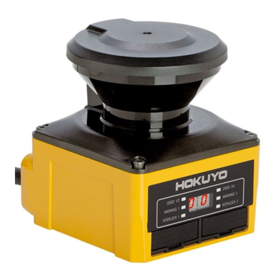
3.2 Components of UAM-05LP Optical window Housing USB Connector Ethernet Connector SD card slot Connector Cable 7-segment display Figure 3-1 UAM-05LP components Document No: C-61-00003-3... - Page 15 Figure 3-2 Scanning range and detection zone origin (Top view) Figure 3-3 Detection plane of UAM-05LP (Side view) Document No: C-61-00003-3 ...
-
Page 16: Operation Principle
3.3 Operation principle Warning zone 2 Warning zone 1 Protection zone Figure 3-4 Scanning range Figure 3-4 shows the scanning range of UAM. Protection zone and warning zones are configured using the UAM Project Designer application software. Any object or human beings entering the protection zone will lead the OSSD signal to change from ON-state to OFF-state. -
Page 17: Scanning Area
Figure 3-5 TOF operation principle 3.4 Scanning area Scanning area of UAM consists of protection zone and warning zones. Maximum 32 sets of area can be configured. Further, two combinations for protection and warning zones can be selected for the operation. Combination 1: Protection zone, Warning zone 1 and Warning zone 2 Combination 2: 2 Protection zones (Dual Protection) In dual protection mode, two protection areas can be configured but it is not possible to configure the... - Page 18 Figure 3-6 Protection zone configured using manual mode Figure 3-7 Protection zone configured using teaching mode User should verify the configuration before actual operation. The configured zone should be of minimum safety distance or more. Figure 3-7 Protection zone configured using teaching mode ...
-
Page 19: Warning Zone
In dual protection mode, two protection zones can be configured independently. UAM will monitor these zones simultaneously. OSSD1 and OSSD2 are dedicated to protection zone1 and OSSD3 and OSSD4 are dedicated to protection zone2. Figure 3-8 shows an example of the dual protection zone configuration. Warning zones cannot be configured in dual protection mode. -
Page 20: Area Switching
Warning zone 2 Warning zone 1 Protection zone Figure 3-9 Warning zones Warning zones are non-safety zones. Warning signals should not be used for controlling any machine or vehicle for the safety-related purposes. Warning signals are non safety-signal. ... - Page 21 it can operate with maximum 32 sets of area. Further, it is also possible to switch the area through the speed monitoring of incremental encoder signal connected to UAM page 24 Table 3-1 Input combination for area switching Max encoder area ...
- Page 22 Table 3-2 Input combination for area switching a) In the case of 5 input signals IN_ Area IN_A IN_B IN_C IN_D IN_E Area 1 OFF OFF Area OFF Area OFF Area Area5 OFF Area6 OFF Area7 OFF Area8 OFF...
- Page 23 b) In the case of 4 input signals IN_ Area IN_A IN_B IN_C IN_D Area 1 OFF Area OFF OFF Area Area OFF Area5 OFF Area6 OFF Area7 OFF Area8 OFF Area9 ON Area10 ON Area11 ON Area12 ON...
-
Page 24: Incremental Encoder
3.6 Incremental encoder In UAM there are 2 pairs of encoder input terminals for connecting 2 units of dual channel incremental encoder signals. Area will be switched depending on the encoder speed. Direction of travel is detected by encoder's phase A and phase B signals having the phase difference of 90°. Speed and rotating direction of both encoders are constantly monitored to detect abnormal travel and stop the AGV. -
Page 25: Pulse Per Cm Travel Generated By Incremental Encoders
3.6.1 Pulse per cm travel generated by incremental encoders When AGV travels, incremental encoder generates pulses due to the transmission ratio between AVG tires and incremental encoder frictional wheel. Pulse count per cm depends on AGV's speed. Figure 3-11 Calculation of pulse count per centimeter travel AGV tire diameter: 40 cm ... -
Page 26: Recommend Incremental Encoder Specification
In the explanation above, the transfer method of the rotation was based on the frictional wheel. Same method can be applied for other cases to estimate the pulse count generated for one rotation of the wheel. User should verify the proper area switching through encoder inputs. ... -
Page 27: Area Switching By Encoder Input
Table 3-3 Relation between AVG speed and tolerance AGV speed v (cm/s) Tolerance -9≦ v ≦+9 Infinity -30<v<-9 or 9<v<30 v≦-30 or +30≦v v<-9 or +9<v 0.3s (Two encoders with different rotating direction) 3.6.4 Area switching by encoder input When encoder setting is enabled, four patterns can be selected from two available external inputs. -
Page 28: Ossd
In this example, speed is divided into 4 ranges and each speed range is assigned Area 3 to Area 6. Figure 3-13 (a) Example of encoder input setting When the pattern is set for static input, area number and encoder speed monitoring are configured. Speed monitoring monitors the speed of the encoder and if it exceeds the limit OSSD will be switched to OFF state. -
Page 29: Self-Diagnostic Function Of Ossd
OSSD is a safety related signal and should be connected directly to the relay or device that switches the machine or vehicle under control. Sufficient time for the machine or vehicle must be allocated to stop when configuring the response time of OSSD. -
Page 30: Interlock Function
3.7.3 Interlock function Interlock is a function to prevent automatic restart of the OSSD signal switching from OFF-state to ON-state. Automatic restart, manual restart and manual start interlock functions are configurable using the UAM Project Designer. 3.7.3.1 Automatic restart UAM will restart automatically when interlock function is disabled or only the start interlock function is enabled. - Page 31 OSSD's OFF-state is due to an internal fault, it will remain in OFF-state even when reset signal is provided. Reset delay is configurable in the range of 1s to 6s. Figure 3-16Timing chart of manual restart User should verify that the detected obstacle is safely removed before resetting the UAM.
-
Page 32: External Device Monitoring (Edm) Function
Figure 3-17 Manual start sequence 3.8 External device monitoring (EDM) function EDM is a function that monitors the state of the input signal from the controlled machine or automated guided vehicle (AGV). EDM is configured using the UAM project designer. When EDM function is enabled, any fault detected in EDM signal will switch the OSSD signal to OFF-state. -
Page 33: Muting Function
Figure 3-19 EDM timing chart In dual protection mode, EDM2 circuit and timing chart for OSSD3 and OSSD4 are same as above. 3.9 Muting function Muting function temporarily suspends the safety function in the configured zone of UAM when the specified conditions are fulfilled. -
Page 34: Muting Stop Condition
▶ 10seconds When using muting function in dual protection mode, Muting 3 and Muting 4 are configured in the similar way. 3.9.2 Muting stop condition Muting function will stop when any one of the condition below is fulfilled: a) One of the muting inputs switches to OFF-state. b) When the predefined (preset) maximum muting time T2 exceeds (1 minute and above) (Figure 3-20). -
Page 35: Muting Override Function
3.9.3 Muting override function Muting override is a function to recover UAM when the OSSD is switched to OFF state due to muting related errors by temporarily suspending the safety function. Override function is active when the override input (OVERRIDE 1/2) and the reset input (RESET 1/2) are switched in a sequence. Figure 3-21 shows the override sequence. -
Page 36: Reference Monitoring Function
When using muting override in dual protection mode, Muting 3, Muting 4, Override input 2 and Reset input 2 are configured in the similar way. When muting function is enabled, user must ensure the safety of the protection zone. ... -
Page 37: Access Protection
3.10.2 Access protection An example of reference monitor function used for access protection is shown in figure 3-23(a), (b). Reference segments should be configured on each surface for displacement detection. Reference segments should be configured such that displacement can be easily detected. The OSSD will switch to OFF-state when access penetration is detected, and also if the distance between UAM and the reference structure changes. - Page 38 Figure 3-23 (b) Front view of the access detection using reference monitor function Figure 3-23(c) Incorrect configuration of reference segment Document No: C-61-00003-3...
-
Page 39: Area Sequence Function
3.11 Area sequence function Area sequence is a function to monitor sequences of area switching. When this function is activated, OSSD signal will switch to OFF-state if the switching pattern is other than the configured sequence. This function prevents the machine to operate with random protection zone. From each area, switching selection to maximum 31 other areas is possible when configuring the area sequence. -
Page 40: Other Outputs
Table 3-4 Response time of UAM Response time (ms) Response time (ms) Default value * * Default value of OFF response time varies depending on the selected application when creating a “New” project. See Table 4-11 for the details. * Minimum configurable response time in Master/Slave mode is 120ms for OFF and 300ms for ON. -
Page 41: Reset Request 1 (Res
3. 13.5 Reset Request 1 (RES _ REQ1) This signal will switch to ON-state when the protection zone 1 of the UAM is ready to receive reset signal. 3.13.6 Reset Request 2 (RES _ REQ2) This signal will switch to ON-state when the protection zone 2 of the UAM is ready to receive reset signal. -
Page 42: Led
3.14.1 LED LED indicators and their descriptions are shown in Table 3-5. Table 3-5 Description of indicator LEDs Color Description Green LED when OSSD 1/2 signal is in ON state, OSSD 1/2 Green/Red Red LED when OSSD 1/2 signal OFF state Green LED when OSSD 3/4 signal is in ON state, OSSD 3/4 Green/Red... -
Page 43: Ethernet Communication
Measurement data of UAM can be obtained from the Ethernet communication. Water proof Ethernet connector is located at the back of UAM. To connect sensor with PC use an Optional Ethernet cable (UAM-ENET). UAM is compatible with SCIP2.2 communication protocol standard. Refer to UAM-05LP communication specification (C-64-00012). ... -
Page 44: Function To Configure Uam By Sd Card
Figure 3-27 IP initialization switch 3.16 Function to configure UAM by SD card Configuration generated by UAM Project Designer can be saved in the SD card. It is possible to transfer the setting directly from the SD Card to UAM without connecting to a PC. Recommended specification of SD card is given below. - Page 45 Figure 3-28 Connection example (When OSSD of slaves are not in use) Perform the risk assessment before using the master-slave function. User should comply with all the following conditions when using the master-slave function. 1.
-
Page 46: Laser Off Mode
Configured active area count in master and slave units should be the same except when using the encoder input function. Scanning area operation mode in master and slave units should be the same. 3.18 Laser Off Mode Laser off mode is a function to completely stop the laser emission in the measurement region in order to prevent the interference to the surrounding equipment. -
Page 47: Optical Window Contamination Warning Function
Table 3-7 Response time for different scan skip settings Master-Slave function disabled Scan skip count Off Response time (ms) Scan skip count On Response time (ms) Master-Slave function enabled Scan skip count Off Response time (ms) Scan skip count On Response time (ms) 3.20 Optical Window Contamination Warning Function This is a function to warn the optical window contamination by blinking the 7-segment display number... -
Page 48: Application Examples Of Uam
4. Application examples of UAM The section describes some application examples of UAM and safety distance calculation in the respective application. When using the UAM as protective equipment, guidelines below should be taken into account. Hazard should be identified and risk assessment should be carried out. ... - Page 49 Figure 4-2 Top view of the horizontal application Figure 4-3 Side view of the application Document No: C-61-00003-3 ...
-
Page 50: Access Protection (Stationary Horizontal Application With Dual Protection Zone)
For safety distance calculation: × where: Safety distance (mm) Approach speed 1600 (mm/s) Maximum stopping/run-down time of the machine or system (s) Response time of UAM (s) 1200-0.4×H≧ 850 the height at which the protective field is mounted (mm) 1000≧... -
Page 51: Access Protection (Vertical Application- Whole Body Detection)
The safety distance for this application is shown in figure 4-1. Protection zone 1 Protection zone 2 Figure 4-4 Example Horizontal application of access protection (Dual protection zone) 4.3 Access protection (Vertical application- whole body detection) UAM can be used as a protective shield by mounting it vertically (Figure 4-5). Application shown in the figure is generally used in preventing the access to hazardous area. - Page 52 Figure 4-6 Top view of access protection (Whole body detection) Figure 4-7 Side view of access protection (Whole body detection) For Safety distance calculation: S=(K× ( Tm+Ts))+C where: Document No: C-61-00003-3...
-
Page 53: Access Protection (Vertical Application Stationary)
S = Safety distance (mm) K = Approach speed 1600 (mm/s) = Maximum stopping/run-down time of the machine or system (s) = Response time of UAM (s) C = Additional distance of 850mm by considering arm intrusion (mm) User should ensure that the width of unprotected zone “a”... - Page 54 Figure 4-8 Front view of access Figure 4-9 Side view of access protection (For detection of body parts) For Safety distance calculation S= (K×(Tm+Ts)) + C where S = Safety distance (mm) K = Approach speed 2000mm/s = Maximum stopping/run-down time of the machine or system (s) = Response time of UAM (s) C = Additional distance ×...
-
Page 55: Area Protection (Horizontal Application Mobile) Fixed Area
O = Additional width from edge of hazard source ≥ 2 × − d = Minimum detectable object width (mm) = UAM’s tolerance distance (mm) In the access protection application, where the angle of the approach exceeds ±30º, “Reference boundary monitoring”... - Page 56 Figure 4-11 Top view of area protection (Mobile) Figure 4-12 Side view of area protection (Mobile) For Safety distance calculation: × × where: S = Safety distance (mm) V = Maximum approaching speed of AGV (mm/s) = Maximum stopping/run-down time of the machine or system (s) = Response time of UAM (s) = Distance required for AGV to stop (mm) L= Brake wear coefficient...
- Page 57 = Additional of distance with the lack of ground clearance (mm) h = Ground clearance (mm) When using the UAM on an AGV, user should confirm the time and distance required for the AGV to stop completely as it will move forward during the response time of UAM. It is important to note that distance required to stop is not proportional to the speed, but proportional to the square of the speed.
-
Page 58: Area Protection (Mobile, Horizontal, Single Protection, Variable Area)
4.6 Area protection (Mobile, Horizontal, Single Protection, Variable Area) For applications where AGV travels in a single direction, it is possible to switch to different areas at corners for effectively monitoring the obstacles at front (Figure 4-14). Warning zone 2 Warning zone1 Protection zone Left turn... -
Page 59: Area Protection (Mobile, Horizontal, Single Protection, Encoder Input)
4.7 Area protection (Mobile, Horizontal, Single Protection, Encoder Input) When incremental encoder is used, area can be switched depending on the speed of AGV (Figure 4-15). Warning zone 2 Warning zone 1 Protection zone High speed Medium speed Low speed Figure 4-15 Example of AGV’s scanning area depending on the speed (Top view) 4.8 Area protection (Mobile, Horizontal, 2 Units Interconnected, Variable Area) -
Page 60: Area Protection (Mobile, Horizontal, 4 Units Interconnected, Variable Area)
Protection zone Warning zone 1 Warning zone2 Figure 4-16 Example of AGV’s scanning area which can travel in both the direction (Top view) 4.9 Area protection (Mobile, Horizontal, 4 Units Interconnected, Variable Area) For AGVs travelling in all directions it is possible to use 4 interconnected units of UAMs mounted on each side of AGV. -
Page 61: Area Protection (Mobile, Horizontal, Autonomous Navigation)
Ethernet to the main control unit of AGV. Supplied data can be used for autonomous route selection. For such systems, there is no need to install guidance means such as optical beacons or electromagnetic tapes on the floor. Refer to UAM-05LP communication protocol (C-64-00012) for the Ethernet communication protocol.... - Page 62 Table 4-1 Default values for selected applications Sensing Interlock Reference Off response time Applications Minimum Active Start/Restart Monitoring (Common to all areas) Delay detection width areas Setting (Tolerance) General 70mm 150ms Access protection 70mm Manual/Auto 150ms (Horizontal application Stationary) Access protection Used 70mm...
-
Page 63: Installation
5. Installation Cautions during the installation of UAM are explained in this chapter. 5.1 Light interference UAM uses pulsed laser for object detection. Light sources in the surrounding could interfere with its operation leading to false detection. User should examine the surroundings environments before installing the UAM. -
Page 64: Mutual Interference
5.2 Mutual interference Cautions are required while using two or more units of UAM or identical products as pulsed laser signal from one another could lead to false detection. Figures below show the installation method for avoiding the mutual interference. a) Changing the height of installation Install at different heights to separate the mutual detection plane by 5 degrees or more.... - Page 65 b) Changing the angle of installation Change the installation angle of UAM by 5 degrees or more from the mutual detection plane. Figure 5-4 Opposite facing installation Figure 5-5 Parallel installation C) Adding a shield between UAMs Add a shield between UAMs such that laser beam of one unit cannot reach the other to avoid the possible mutual interference.
-
Page 66: High Reflective Background
Figure 5-7 Parallel installation Shielding material should be opaque. 5.3 High reflective background Measured value will be longer than the actual distance of the object due to high reflective background leading to wrong OSSD output. When high reflective background cannot be avoided in the working environment, additional distance of 200mm is necessary while configuring the protection and warning zones (Figure 5-8). -
Page 67: Limited Detection Capability Zone
Measured value will be longer than actual distance of the object if the background is highly reflective. Additional distance should be included when configuring the protection zone. High reflective background (Ex.: Mirror, corner cube reflector, reflective safety jacket, road reflector) should be avoided. -
Page 68: Wiring
6. Wiring This chapter describes safety precaution when wiring the UAM. 6.1 Precautions During electric wiring make sure that all devices are disconnected from power supply. Switch off all the power supply during wiring. Confirm that power supply is OFF. ... -
Page 69: Wiring Example
Encoder input 2 B IN_E/EDM2 Area switching Input E invert / External Green/Black Input device monitoring 2 Yellow/Green RESET 1 Reset input 1 Input Yellow/Blue RESET 2 Reset input 2 Input RES_REQ1/MUT_OUT1 RES_REQ1: Request output 1 Orange Output MUT_OUT1:Muting state output 1 RES_REQ 2/MUT_OUT 2 RES_REQ2:... - Page 70 R1 and R2: External equipment (Safety relay, Electromagnetic contactor) S1: Interlock reset switch *1: Refer to section 3.5 for the detail on area switching. b) During EDM, muting and override function Figure 6-2 Wiring Example 2 R1 and R2: External equipment (Safety relay, Electromagnetic contactor) S1:Interlock reset switch S2:Override switch M1 and M2:Muting switch 1 and 2...
- Page 71 c) During area switching during encoder input Figure 6-3 Wiring Example 3 R1 and R2: External equipment (Safety relay, Electromagnetic contactor) S1:Interlock reset switch *1: Refer to section 3.5 for the detail on area switching and section 3.6.4 for encoder input. ...
- Page 72 d) During Master slave function when not using OSSD of slave Master Slave1 R1 and R2: External equipment Slave2 (Safety relay, Electromagnetic contactor) S1:Interlock reset switch *1: Refer to section 3.5 for the detail on area switching. Slave3 Figure 6-4 Wiring Example 4 ...
- Page 73 e) During Master slave function when using OSSD of slave Master Slave1 R1 – R8: External equipment (Safety relay, Electromagnetic contactor) Slave2 S1-S4:Interlock reset switch *1: Refer to section 3.5 for the detail on area switching. Slave3 Figure 6-5 Wiring Example 5 ...
-
Page 74: Input/ Output Circuit
6.5 Input/ Output circuit 6.5.1 OSSD/ Warning Output circuit OSSD/Warning output is output source type Figure 6-6 OSSD/WARNING Output circuit 6.5.2 Other output circuits RES_REQ1, RES_REQ2, MUT_OUT1, MUT_OUT2 outputs are PNP type. Figure 6-7 Output circuit ... -
Page 75: Input Circuit
6.5.3 Input circuit Figure 6-8 shows input circuit for Area input, EDM1, EDM2, RESET1, RESET2, MUTING 1, MUTING 2, MUTING 3, MUTING 4, OVERRIDE 1, and OVERRIDE 2 signals. Figure 6-8 Input circuit Document No: C-61-00003-3 ... -
Page 76: Function Configuration Of Uam
7. Function configuration of UAM 7.1 About UAM Project Designer application UAM project designer is application software for UAM that is developed for the following functions. Protection and warning zone configuration Function configuration Displaying the measurement data ... -
Page 77: Installatiion Of Uam Project Designer
Even if the system requirements are fulfilled, operation is not guaranteed in all PCs. Read the UAM user’s manual before configuration. User’s manual can be opened from the help menu of UAM Project Designer. Cover the USB connector and SD card slot with protective cap when UAM is ... -
Page 78: Device Driver Installation
Click [OK] when uninstalling process is complete. Restarting the PC is recommended. 7.4 Device driver installation 7.4.1 Installing the driver in Windows 8 In Windows 8, permission setup is required before installing the USB driver. Caution: This step is not required for Windows 7. Proceed to section 7.4.2 for such OS. This step is not required for Windows XP. - Page 79 On the PC setting screen, click the “General” and then “Restart Now” of “Advanced start-up” on the list. Figure 7-3 PC Setting screen Wait for the system to restart. On the option selection screen, click the “Troubleshooting” → “Detailed Options” → “Startup setting” in order .
-
Page 80: Installing The Driver In Windows 7
Figure 7-4 Option selection screen Figure 7-5 Startup setting screen Click restart and wait for a while. When startup setting is displayed, press F7 or 7. After completing the setup, follow the process described in section 7.4.2 to install the driver. To view the device manager used in the process, right click the mouse button on the empty start window panel and click on the “all applications”... - Page 81 Step 2: From windows start menu click [Computer]. Figure 7-7 Step 3: Click [System properties] on the menu. Figure 7-8 Step 4: Click [Device Manager] button. Figure 7-9 Document No: C-61-00003-3 ...
- Page 82 Step 5: [URG-Series USB Driver] will be listed on [Other devices]. Right click on the [URG-Series USB Driver] and click [Update Driver Software]. Figure 7-10 Step 6: Select [Browse my computer for driver software] when following message appears. Figure 7-11 ...
- Page 83 Step 7: Insert installation CD on the PC. Click [Browse] button to select “Driver” folder in the CD and click [Next] button . Figure 7-12 Step 8: Select [Install this driver software anyway] if following security message appears during installation. Figure 7-13 ...
- Page 84 Step 9: Installation is complete when following message appears on the screen Figure 7-14 Step 10: Open device manager and confirm the presence of [URG Series USB Device Driver] listed under [Ports (Com & LPT)] Figure 7-15 Document No: C-61-00003-3...
-
Page 85: Installing The Driver In Windows Xp
7.4.3 Installing the driver in Windows XP This section explains the USB driver installation method in Windows XP. URG series USB driver is used by UAM. Follow the steps below to install the driver. Connect the UAM to PC’s USB port. When PC detects the new hardware open the “Found New Hardware Wizard”... -
Page 86: Starting The Uam Project Designer
Figure 7-16 USB Driver in Windows 10 7.5 Starting the UAM Project Designer * Explanation of this section is based on Microsoft Windows XP. Although the display may differ slightly in the other OS, same operation can be performed. a) Supply the Power to the sensor. -
Page 87: Create New Configuration
b) Select the method to operate UAM. Table 7-2 Operating Method Method Description Create Checks the firmware version and creates a new project file for UAM. Opens an existing project file. Open Connect Establish communication between PC and sensor. 7.5.2 Create new configuration When new is selected, a list of application examples as shown in Figure 7-18 will be displayed. -
Page 88: Open Configuration File
7.5.3 Open configuration file When the open is selected, a window as shown in figure 7-20 will be displayed. Select the previously saved project, click open to read the settings. Modify the settings if required. Confirm all the settings and proceed to transmit to transfer the configuration to UAM. -
Page 89: Components Of Uam Project Designer
7.6 Components of UAM Project Designer Figure 7-22 shows the name of each component on the main window. Menu bar Tool bar Sub panel Status bar Main window Figure 7-22 UAM Project Designer components Document No: C-61-00003-3 ... -
Page 90: Menu Bar
7.7 Menu bar This section explains the functions of all items in the menu bar. Function can be executed by either clicking the respective items or by the short-cut key. When UAM is not connected, some items are in gray and cannot be clicked ... -
Page 91: Mode
Table 7-4 Edit Item Short-cut Key Function Ctrl+Z Undo It will undo the previous operation. It will redo the last operation. Ctrl+Y Redo Copy single area. Ctrl+C Copy Ctrl+X Cut single selected area. Delete the original area. Ctrl+V Paste Paste the selected area in other area.... -
Page 92: Language
Table 7-6 Connection Item Short-cut key Function Connect ― Connects to UAM ― Disconnect Disconnects UAM 7.7.5 Option When option is clicked, items as shown in the Figure 7-27 will be displayed. Table 7-7 shows the details of each item. When UAM is not connected some items are in gray and cannot be selected. Figure 7-27 Option ... -
Page 93: Help
7.7.7 Help When help is clicked, items as shown in the Figure 7-29 will be displayed. Table 7-9 shows the details of each item. Figure 7-29 Help Table 7-9 Help Item Short-cut key Function Manual Ctrl+M Displays the user manual XML file format Displays format details of XML file About the application... -
Page 94: Tool Bar
7.8 Tool bar Frequently used functions are listed on the tool bar. Details of the item are shown in table 7-10. When UAM is not connected some items are displayed in gray and cannot be selected Table 7-10 Tool bar Icon Function... -
Page 95: Subpanel
7.9 Subpanel This subpanel is used for switching the UAM modes (Configuration, Monitor and Report). When items cannot be used they are displayed in gray. 7.9.1 Configuration tab There are 6 tabs under the configuration main tab (Load from SD card, General, Function, Area, Confirm and Save to SD card). - Page 96 Table 7-11 General Item Description General Product identity Enter ID for UAM (Size limit : 64 characters) User name Enter User name (Size limit : 50 characters) IP address Set the IP address Subnet mask Set subnet mask address Default gateway Set the default gateway address C) Functions...
- Page 97 Item Description Check to enable the sensing function Min detection width (mm) 30, 40, 50, 70, 150 Active areas : Area 1 to Area 32 Area input delay :30ms (Default), 120ms, 270ms, 1s, 2s Sensing Operation mode : Protection 1 + Warning 1/2, Protection 1, 2 ...
- Page 98 Item Description Detailed area setting for each pattern. For the encoder input set speed division count and area for each speed range. It is not possible to select same area for two different speeds. For static input, select the area and enable or disable speed monitoring. If speed monitoring is enabled it is necessary to provide the speed range.
- Page 99 D) Area User can configure and edit area shapes. Details of each component are explained below. ⑫ ② ④ ⑪ ⑥ ① ⑨ ⑦ ⑩ ⑤ ⑧ ③ Figure 7-32 Area configuration tab <Area>...
- Page 100 Shapes of all the areas are displayed. ⑦ Mouse position If the cursor is placed on the configured area, sensor coordinate represented by the mouse pointer is displayed. Table 7-13 explains in detail. ⑧ Zoom In, Zoom Out tool Adjust the area display screen ratio.
- Page 101 Table 7-15 Drawing assistance icons Icon Function Move the configured area When line segment is drawn by moving the mouse, a triangular shape is drawn by connecting the two points of the line and the origin. When coordinates of start and end points of a line are specified numerically, a triangular shape is drawn by connecting these points with the origin.
- Page 102 Table 7-16 Rotate and reverse icon Icon Function It will undo the previous operation It will redo the last operation Rotate the area and measurement data display window Reverse the area and measurement data display (left to right or right to left) Table 7-17 XML file icon Icon Function...
- Page 103 E) Confirm After completing all the configurations, they can be reviewed by clicking the confirm button followed by the steps shown in Figure 7-33(a) to (c). Return back to the respective tab if correction is necessary. Click the “Transmit to sensor” button if configuration has no error to write it into UAM if it is connected or “Save to SD card”...
- Page 104 Figure 7-33(b) Function Figure7- 33(c) Area Document No: C-61-00003-3...
- Page 105 F) Transmit to sensor/ Save to SD card Click “Transmit to sensor” button if error is not found during confirmation to transmit the configuration to the UAM. If device is not connected, click “Save to SD card” button to save the setting file into the SD card memory.
-
Page 106: Monitor Tab
7.9.2 Monitor tab User can monitor the detection state of the UAM by selecting the monitor tab. Figure 7-35. Monitor tab 7.9.3 Report tab Report tab is only functional when the UAM is connected to the application. There are 3 types of reports: Project report, Error report and Detection Log report. - Page 107 Figure 7-36(a) Project report tab Figure 7-36(b) Error report tab Document No: C-61-00003-3 ...
- Page 108 Figure 7-36(c) Detection log report tab Table 7-18 Report display items Report Items show in report Product identity User name Date Sensor information Ethernet information Sensing Operation mode Project Interlock ...
-
Page 109: Status Bar
7.10 Status bar This section displays the model, serial number, firmware version of the connected sensor. Icons on the right show connection state. Table 7-19 explains the meaning of each icon. Table 7-19 Status bar icon Icon Description Indicates the connected state with UAM. Indicates the disconnected state with UAM.... -
Page 110: Password
7.12 Password Configuration of UAM is password protected for preventing unauthorized access. User should enter the password before proceeding to configuration screen. When the window as shown in the figure 7-37 is displayed, enter the password and click ok. Default password is 12345678. Figure 7-37 Password 7.12.1 Changing the password User can change the password by performing the following steps:... -
Page 111: Reclaim The Forgotten Password
7.12.2 Reclaim the forgotten password When the password is forgotten, follow the steps below to reclaim the password. a) Click the File of the menu bar. b) Click the Save As or press Ctrl + S and save the project at a preferred location. Project will be saved in the file [*****.huc]. -
Page 112: Function Configuration
7.14 Function configuration User can configure various functions of the UAM through UAM project designer. Click on the [Function] tab to display the list of configurable functions (Figure 7-40). Put a check mark to activate the corresponding function (refer to section 7.9.1 for detail). List of configurable functions are shown below. There are some functions which cannot be used simultaneously * . -
Page 113: Area Configuration
7.15 Area configuration When Area tab is clicked, area configuration screen will be displayed as shown in figure 7-41. There exist two types of regions, one where configuration of protection and warning zones are possible and the other where it is not. Range shown in the white represents the region where it is possible to configure the protection zone. -
Page 114: Area Configuration By Drawing Tools
7.15.1 Area configuration by drawing tools Zones can be configured using the drawing tools on the UAM project designer. Refer to Table 7-15 for the details. Click on the Add button. Select the drawing shape. Move the cursor inside the setting possible region and draw the shape by drag and drop operation. While drawing it is possible to switch the shapes to draw areas with combination of shapes. - Page 115 Coordinates of configured points where the numeric values are shown can be edited directly by double clicking on the cell. It is also possible to switch between XY coordinates and polar coordinates. Further, a new point can be added by clicking on the + button on the Pt. column. * Use backspace key to delete a single coordinate point on the display panel.
-
Page 116: Area Configuration By Teaching Function
7.15.2 Area configuration by teaching function Automatic zone configuration by referring the boundary can be done by using the UAM’s Teaching function. This function is useful when user needs to configure complex zone or would like to reduce the time for zone configuration. - Page 117 Figure 7-46 Area configured by teaching When the stop button is clicked, an area is generated by the smallest data recorded. Configured area will resemble the UAM’s background. (Figure 7-46). When configuring the protection zone, if the background is not within the maximum detection distance it is set to maximum detection distance of UAM.
-
Page 118: Muting Configuration
7.15.3 Muting configuration Muting function temporary suspends the safety functions of UAM when required conditions are fulfilled. Follow the steps below to configure muting function. Confirm that muting function is enabled in the function tab. Before configuring the muting zone it is necessary to configure the protection zone. Configure the protection zone if it is not yet configured. -
Page 119: Reference Region Configuration
Protection zone Muting zone Figure 7-48 Muting zone configuration example 2 Muting zone configuration example as square is drawn from point 1 to point 2 7.15.4 Reference region configuration Follow the steps below to configure reference region. Ensure the UAM is firmly mounted at its location. ... -
Page 120: Transmit Configurations To Uam
Figure 7-49 Reference region configuration example For example, to monitor the sensor’s displacement by referring the background, choose the line drawing tool and draw a line segment over the background by mouse drag and drop. Reference region with the ±tolerance is generated on that location (Figure 7-49). - Page 121 Figure 7-50 Confirm monitor example When transmit button is clicked verification window appears (Figure 7-51). Click yes to transfer the configuration to UAM Figure 7-51 Reference monitor configuration example It may take few minutes to transfer the settings to UAM. When transfer is completed UAM will restart automatically.
-
Page 122: Save Project File
7.17 Save project file Configured functions and area can be saved into a file as a project. Follow the steps below to save the project file. a) Click File from the menu bar. b) Click Save As. (Figure 7-52) Figure 7-52 Save project file c) Enter a file name and click Save button. -
Page 123: Read Configuration From Uam
7.18 Read configuration from UAM User can check the current settings or confirm the configurations of the UAM by performing the following steps. Confirm the UAM and UAM Project Designer is connected. Select Load settings on the sub panel window. Progress panel will appear (Figure 7-54) showing the state. -
Page 124: Recording The Uam Data
Figure 7-55 Save project file 7.20 Recording the UAM data Follow the steps below for data recording. Connect UAM with UAM Project Designer. Click the monitor button on sub panel. Application will switch to monitor mode. Click the recorder button. Figure 7-56 Recorder button Data recording window will appear. -
Page 125: Replay The Log Data
Enter the number of scans in the scan limit field (Figure 7-57) and click the record button. Application will automatically create the file click save. Change the file name and folder if necessary. Data recording will start and stops automatically when the specified scan count is completed. Click the stop button to terminate the recording before reaching the scan count. - Page 126 Select the log data file for re-playing (Figure 7-59). Figure 7-59 Log player window 2 Click the open icon to choose the file for re-playing and click the play icon to start viewing the log data. Move the slider bar to the desired position to view the specific scan data. Control icons are explained in Table 7-20.
-
Page 127: Save Settings To Sd Card
7.22 Save settings to SD card Configuration data can be saved in the SD card which in turn can be used for directly configuring the UAM without connecting it to the PC. <Steps to save> a) Configure a project in the UAM Project Designer and click confirm button when it is complete. b) In the confirmation tab, check the general, function and area settings in order. -
Page 128: Uam Configuration Through Sd Card
Figure 7-61 SD Card selection screen Figure 7-62 Transmission complete window 7.23 UAM configuration through SD card Configuration from the SD card is possible for the devices whose serial number and password are registered in the SD card. Devices whose serial number or password does not match cannot be configured. -
Page 129: Inspection And Maintenance
8. Inspection and maintenance Inspection and maintenance are necessary for safety operation. User must ensure the inspection and maintenance are carried out as specified in the user’s manual. Before performing inspection and maintenance, confirm the following items. The machine or AGV monitored by UAM is switched OFF. ... -
Page 130: Operation Inspection
If the muting function is configured, UAM does not switch to mute state when the muting input sequence is different than the specified sequence. If the muting function is configured, UAM does not switch to mute state when the time interval between two muting inputs exceeded the specified time interval If the muting function is configured, the override function is terminated when the override period exceeds the... -
Page 131: Daily Inspection
piece is removed If the UAM is in manual restart mode, OSSD remains in OFF-state when UAM is restarted If the UAM is in automatic restart mode, OSSD signal switches from ON-state to OFF-state when the test piece is placed inside the protection zone and switches from OFF state to ON state when the test piece is removed If the UAM is in automatic restart mode, OSSD remains in... -
Page 132: Periodical Inspection
is moved inside the protection zone The OSSD signal switches from OFF state to ON state when the test piece is removed from the protection zone If the UAM is in automatic restart mode, OSSD signal switches from ON-state to OFF-state when the test piece is placed inside the protection zone and switches from OFF-state to ON-state when the test piece is removed If the UAM is in manual restart mode, OSSD signal... - Page 133 shows an example of periodical inspection items. It is recommended to perform this inspection at every six months interval. This inspection should be performed together with the daily inspection. Table 8-4 Periodical inspection list example Condition Check item Remark Screws are tightly fastened No displacement from the original mounting position...
-
Page 134: Cleaning The Optical Window
If the muting function is configured, the muting is terminated when muting period exceeds the specified maximum muting period If the reference monitoring function is configured, displacement of the reference boundary structures or UAM should cause the OSSD to switch to OFF-state when displacement exceeds the allowable tolerance. -
Page 135: Replacing The Optical Window
8.6 Replacing the optical window Replacement of the optical window is needed in the following circumstances: Crack or scratch on the optical window. The surface of optical window remains contaminated even after cleaning. Deterioration of the optical window. Order the replacement optical window at the nearest distributor or to UAM sales representative. -
Page 136: Adjustment Of The Optical Window
detection capability of UAM. If there is contamination around the case, remove it with a clean cloth without touching the optical part. If there is contamination on the optical mirror remove it with an air blower. Set a torque wrench to 0.63Nm. - Page 137 Figure 8-2 Optical Window Adjuster d) Click connect button after UAM is detected and COM port number is displayed. Click search, if COM port number is not displayed. e) Click Start Adjustment button when it is enabled. When application is ready, password window will appear. Enter the password of the device and click “OK”...
-
Page 138: Troubleshooting
9. Troubleshooting This chapter describes troubleshooting methods while operating the UAM. Table 9-1 below shows the troubleshooting list. Table 9-1 Troubleshooting list Situation Possible reason Solution suggestion Power supply is Make sure power supply is ON OFF /Over voltage/ Check the supplied voltage.... - Page 139 UAM is interlocked Check the configuration of the interlock function. If RES_REQ is ON, supply UAM with RESET signal Table 9-2 shows the error number of the UAM. These numbers are displayed on the 7-segment display of UAM. If UAM is unable to resume the normal operation, contact the nearest distributor or sales representative (included in last page of the manual) for support.
- Page 140 Optical interference/High Mount UAM at a location free Automatic recovery or Input reflective background from light interference. Refer to reset (During Interlock chapter 5.1 for light setting) interference counter measures. Operating temperature Make sure that operating Restart the power supply error temperature is within specification.
- Page 141 B1-C0 Optical window is Refer to chapter 8.5 for Automatic recovery or Input contaminated cleaning the optical window reset (During Interlock setting) C1 Optical window Replace or clean the optical Restart the power supply removed or contaminated window Adjust the optical window CE...
-
Page 142: Specification
10. Specification 10.1 UAM-05LP Table 10-1 UAM-05LP specification Subject Specifications Model UAM-05LP-T301 UAM-05LP-T301C Protection Range Max: 5m Warning Range Max: 20m (Non-safety) Distance tolerance +100 mm From Black-Reflector Sheet(1.8%)to Retro-Reflector Sheet Detection capability 270 º ... - Page 143 Subject Specifications Output type (High side SW) Output current:(Max:500mA) OSSD 1/2 (Safety) Leak current (Max:1mA) AWG 26 Load tolerance (L/R=25ms, C=1μF) Output type (High side SW) OSSD3/4 (Safety)/ Output current:(Max:250mA) Output WARNING 1/ 2 Leak current (Max:1mA) (Non-Safety) AWG 28 Load tolerance (L/R=25ms, C=1μF) Output types (PNP Transistor)
- Page 144 Humidity 95% RH with no condensation Storage Humidity 95% RH with no condensation Less than 1500 lx Surrounding Intensity Frequency range: 10~55 Hz Sweep rate: 1 octave/min Vibration Amplitude: 0.35 mm ±0.05 mm Bump Acceleration: 98m/s (10G) Pulse duration: 16 ms Not permitted...
-
Page 145: Package Contents
11. Package contents The following items are included in the package. ×1 b) Quick Reference ×1 Configuration CD ×1 Document No: C-61-00003-3 ... -
Page 146: Options
12. Options 12.1 Base mounting bracket (Model: UAM-BK03) This base bracket can be used to change the horizontal alignment of the UAM during installation. This bracket is useful especially in preventing the mutual interference when two or more UAMs are used. (Refer to external dimension) 12.2 Rear mounting bracket (Model: UAM-BK04) This rear bracket can be used to change the vertical and horizontal alignment of the UAM during... -
Page 147: Optical Window For Replacement (Model: Uam-W002)
Replacement part when optical window is scratched or damaged. 12.7 Cover Bracket (Type: UAM-BK05) Cover brackets for optical window protection that can be used in combination with mounting brackets. (See the dimension) 12.8 Connector Cable (UAM-05LP-T301C Only) Model Cable Length (m) UAM-5C02C... -
Page 148: External Dimension
13. External dimension 13.1 UAM-05LP Document No: C-61-00003-3... -
Page 149: Base Mounting Bracket
13.2 Base mounting bracket Document No: C-61-00003-3 ... -
Page 150: Rear Mounting Bracket
13.3 Rear mounting bracket Document No: C-61-00003-3... -
Page 151: Cover Protection Bracket
13.4 Cover Protection Bracket Document No: C-61-00003-3 ... -
Page 152: Ec Declaration Of Conformity
14. EC Declaration of conformity Document No: C-61-00003-3... - Page 153 Document No: C-61-00003-3 ...
-
Page 154: Revision History
15. Revision history Amended No. Revision date Details September 2015 First Release November 2015 UL directives and standards added, Error correction January 2017 Standards updated, Connector model added Following sections added and/or modified Default configuration values added 7-segment upside down display function added Laser off mode added Scan skip function added Minimum detection width of 150mm added... -
Page 155: Representative Contacts
16. Representative contacts Asia and others Hokuyo Automatic Co., Ltd. 540-0028 Osaka HU building, 2-2-5 Tokiwamachi, Chuo-ku, Osaka, Japan Tel: +81-6-6947-6333 Fax: +81-6-6947-6350 E-mail: overseas-sales@hokuyo-aut.co.jp URL: http://www.hokuyo-aut.jp Europe Hokuyo Automatic Co., Ltd. Amsterdam Branch Prof. J. H. Bavincklaan 2, 1183 AT Amstelveen, The Netherlands...
Need help?
Do you have a question about the UAM-05LP and is the answer not in the manual?
Questions and answers
What is A8 alarm