Table of Contents
Advertisement
Quick Links
Specifications
Power Supply
None - self powered
Output
Isolated solid-state switch
DC Output Type: 0.15A @ 30VDC
Switch Rating
AC Output Type: 1.0A @ 240VAC.
-AA3 model: 3A @ 120VAC
<10µA AC or DC N.O., 2.5mA AC N.C., 1.4mA DC
Off State Leakage
N.C.
Response Time
40 to 250 ms
Hysteresis
5%
Fixed core: 1-6, 6-40 & 40-175 A
Input Ranges
Split core: 1.75-6, 6-40 & 40-200 A
4 Turn potentiometer, 15 Turn potentiometer
Setpoint Adjust
-FT Case Style
Isolation Voltage
UL tested to 1480VAC
Frequency Range
6 to 100 Hz
-F Case Style: 0.55 in (14mm) dia.
Sensing Aperture
-S Case Style: 0.85 in (21.7 mm) sq.
-FT Case Style: 0.75 in (19mm) dia.
Case
UL 94V-0 Flammability rated thermoplastic
-Temp -4 to 122°F (-20 to 50°C), 104°F (40°C)
max for model ending in -03
Environmental
-Humidity 0-95% RH, Non-condensing
-Pollution degree 2
-Altitude 2000 meters
cULus listed E222847
Certifications
CE
Sensed Current Limit
Range
Range
Range
Fixed
Split
Continuous
Jumper
Core
Core
None
1 - 6A
1.75 - 6A
200A
Mid
6 - 40A
6 - 40A
200A
High
40 - 175A
40 - 200A
200A
For products intended for the EU market, the
following is applicable to the CE compliance of
the product:
The ACS200 Series may comply with EN 61010-1 CAT III
300V max line-to-neutral measurement category. If insulated
cable is used for the primary circuit, the voltage rating of the
measurement category can be improved according to the
characteristics given by the cable manufacturer.
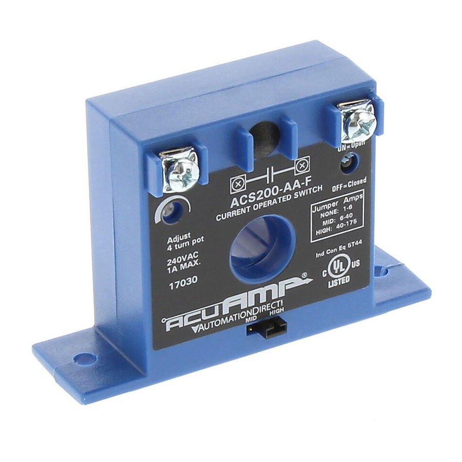
A C S 200 - A
SERIES
SENSOR TYPE:
Switch
AC monitored current
Warning! Risk of hazardous voltage
When operating the device, certain parts may
carry hazardous live voltage (e.g., primary
conductor, secondary terminals). The device
should not be put into service if the installation
is not complete.
Warning! Risk of electric shock or
personal injury
Safe operation can only be guaranteed if the
device is used for the purpose for which it was
designed and within the limits of the technical
specifications. When this symbol is used, it
means you should consult all documentation to
Max. 6
Max.1
understand the nature of potential hazards and
Seconds
Second
the action required to avoid them.
400A
600A
500A
800A
800A
1200A
3505 Hutchinson Road, Cumming, GA 30040
Phone: (800) 633-0405 or (770) 889-2858
Part Number Key
D
- F
CASE STYLE
FT - Fixed Core (terminals on top)
F - Fixed Core (terminals on the side)
S - Solid Core (terminals on the top)
OUTPUT RATING
Blank - 1A 240VAC or 0.15 A @ 30VDC
3
- 3A at 120VAC
OUTPUT TYPE
A - AC
D - DC
OUTPUT (Solid State Switch)
A - Normally Open
C - Normally Closed
AutomationDirect.com (ADC)
ACS200 - Inst - Rev 4
0820
P-N 391000212
ACS200 SERIES
INSTRUCTIONS
Quick Start Guide
1.
Run the wire to be monitored through the
aperture.
2. Mount the sensor or suspend on conductor.
3. Connect output wiring.
a. Use 22-14AWG copper conductors rated
75˚C min only and tighten terminals to 9
in-lbs torque.
b. Make sure the load matches the output
shown on the sensor's label (volts, amps,
AC/DC).
4.
Adjust setpoint.
a. Choose correct range by positioning the
Range Jumper.
b. Use the potentiometer to adjust the
setpoint.
5. Confirm Contact Operation.
If the sensor has an LED, a quick flash indi-
cates current over the setpoint and output
has tripped; slow flash shows current under
setpoint; output is shelf state condition.
®
Advertisement
Table of Contents

Summary of Contents for Automation Direct ACUAMP ACS200 SERIES
- Page 1 Specifications Part Number Key ® Power Supply None - self powered A C S 200 - A ACS200 SERIES Output Isolated solid-state switch CASE STYLE DC Output Type: 0.15A @ 30VDC FT - Fixed Core (terminals on top) Switch Rating AC Output Type: 1.0A @ 240VAC.
- Page 2 CAUTION: Incandescent lamps can have Description “Cold Filament Inrush” current of up to 10 ACS200 Series are solid-state current operated switches. They times their rated amperage. Use caution operate (switch) when the current level through the sensing when switching lamps on and off. aperture exceeds the adjustable setpoint.
Need help?
Do you have a question about the ACUAMP ACS200 SERIES and is the answer not in the manual?
Questions and answers