Table of Contents
Advertisement
Quick Links
Advertisement
Table of Contents

Subscribe to Our Youtube Channel
Summary of Contents for flamco Flexcon M-K/C
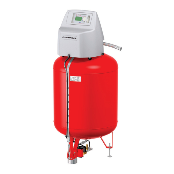
- Page 1 Flexcon M-K/C ®...
-
Page 3: Table Of Contents
2.4 Specifications 2.5 Safety devices 2.5.1 Avoiding excessive pressure 2.5.2 Avoiding excessive temperature 2.6 Signs on the automat Description 3.1 Overview Flexcon M-K/C Automat 3.2 Controller SDS 230 V 1~ 3.3 Working principle Transport and storage 4.1 Transport 4.2 Storage Installation 5.1 Prepare for installation... -
Page 4: General
Do not touch live voltage. The sensor units, diaphragm rupture, and the capacity pressure sensors operate with extra low safety voltage. Flamco shall not be liable for any losses arising from the non-observance of safety conditions or as a consequence of the disregard of standard precautionary measures when performing such services as transport, installation, commissioning, re-starting, operation, maintenance, testing and repair, even in the event that these are not expressly described in these instructions. -
Page 5: 2.5.2 Avoiding Excessive Temperature
Der Kompressormotor ist thermisch gesichert und starter automatisch, nach dem Rücksetzen dieser Sicherung. The compressor motor is thermally protected and will automatically restart when protector resets. Flamco Group P.O. Box 502 3750 GM Bunschoten the Netherlands On the type plate the following product information can... -
Page 6: Description
Description Overview Flexcon M-K/C Automat Name Main switch Cover Cover screw Type plate Steel expansion vessel Cable duct Tensioning belt Foot height adjustment Flexible connection hose Compressor Air filter compressor Cover door Controller unit, 230 V, 50 Hz Pressure relief solenoid... -
Page 7: Controller Sds 230 V 1
Controller SDS 230 V 1~ Name Operating panel, graphic display, LED error display, Selector switch (click and roll). Main switch. ON, glows red. Pico fuse F1, Motor 1, T16A 250 V. Pico fuse F2, Valve 1.1 and 2, T16A 250 V. Serial no. -
Page 8: Transport And Storage
Transport and storage Transport The shipping papers list all the items, such as equipment and documentation. Ensure that the delivery is complete and not damaged. The automats are packed horizontally on disposable pallets and are fully assembled. Accessories can be packed separately or as a part of the automat. Identify the items that are missing or not correctly delivered. -
Page 9: Installation
Installation Prepare for installation Inform the test or certification agencies before installing the automat. Follow the rules of these agencies. Also: • Do not attach the automat to the ground. • Do not pour concrete or plaster over the automat feet. Make sure that the surface can support the maximum weight of the automat, including the water. -
Page 10: Hydraulic Installation
Hydraulic installation • Connect the flexible hose to the automat. • Connect the expansion line. • For installation, only use the flexible hose that is • For an installation example refer to chapter 11. delivered. • Install a shutoff device (A) with drain facility (B). Electrical installation •... -
Page 11: Basic Electrical Connections 230V
Basic electrical connections 230V 1~ Nominal power Nominal current [A] Fuse wiring [kW] connector [A]* Nominal voltage Protection type 0.25 230 V: +6%; -10% IP54 (level sensor IP65) 50 Hz: +1%; -1% SELV: Safety Extra Low Voltage * Recommended value; Line safety switch, characteristic C SELV 28 29 30 31 32 33 34 35 36 10 11 12 13 14 15 16 17 18... -
Page 12: Electrical Connections Accessories
Degassing / ENA 5/10 For pressure step de-aeration of the installation. Can be combined with a pressurisation unit. Flamco-Fill PE pressurisation unit Feeds the installation with water through an atmospheric breaktank and a pump. The level sensor and the make-up time control the unit. -
Page 13: Controller Menu Structure
Startup controller Controller menu structure Process display SYSTEM CLASSIFICATION SYSTEM DATA SYSTEM CONFIGURATION Equipment Menu Process display System (Symbols) Error Data menu ID-Number Manual mode Act. pressure Service Menu Language System press. Actual level Actual filling time, Project number Adjust., content Level quantity (Symbols) Software version Operating mode... -
Page 14: Working Principle Controller
Working principle controller Start up • Switch off an installed refill equipment. • Close the inflow valves. • Switch on the controller (D). Display Error LED Navigation wheel ON/OFF switch controller Use the navigation wheel (C) to navigate through the menus an to confirm the input. -
Page 15: Controller Inputs
Controller inputs Code View System Enter 000000 000001 000001 Back Save Back Save Back Save Back Language Language Zero Setting Mode Deutsch Svenska Norsk ID-number Data Nederlands Norsk Italiano Language Service English Italiano cesky Adjust,content Slovensky cesky Back Back Adjustment,valve Date/Time Zero Setting System pressure... -
Page 16: Fill The Automat
Fill the automat Fill procedure • Do not fill the automat before the necessary start measures are done. • Turn off the main switch of any external filling device. Make sure all shutoff devices on the expansion feed to the return connector (A) are closed. •... -
Page 17: Filling Examples
Filling examples Filling example I: Filling example II: Maximum design temperature: 50 °C Maximum filling Maximum design temperature: 80 °C Maximum filling level: 92% Water trap (minimum water supply), re-feed level: 92% Water trap (minimum water supply), re-feed level: 12% Minimum design temperature: 10 °C Actual level: 12% Minimum design temperature: 10 °C Actual temperature: 44 °C Read out fill level = 74% temperature: 44 °C Read out fill level = 37%... -
Page 18: Maintenance And Troubleshooting
Maintenance and troubleshooting • The water and the contact surfaces can • be 70 °C or more.• • Wear the required protective clothing.• • The floor can be wet or greasy. Wear protective shoes. Release the pressure of the gas compartment and the water compartment before maintenance. After a power failure The programmed parameters of the controller do not change after a power failure. -
Page 19: Error Messages
Check equipment. Operating time The programmed value F1 12 is reached or Test compressor, air filter. compressor exceeded. Flamco Service. Water supply The programmed value F4 6 is reached or Diaphragm pressure to low, check water exceeded. supply. Valve 3 error Valve 3 of the refill equipment is not closed. -
Page 20: Disposal
Disposal Comply with local legislations. • Make sure the system power switch is OFF. • Make sure the main power switch is OFF • Disconnect the power supply. • Close the connection to the system (A). • Remove all the water. •... - Page 21 10 Technical specifications Ø D Nominal operating values of pressure unit Main dimensions (Nominal) Nominal Operating Operating Cont. Automat Feet pitch Height Width Length System capacity pressure tempera- temperature diameter diameter min. connections ture at the DIN ISO- diaphragm 228-1 Tolerance: DIN28011; 28013; 28005-1; DIN7168-1sg. [litres] [bar] [°C]...
-
Page 22: 11 Example Hydraulic And Pneumatic Equipment
Condensate drain Common failure Cap valve Pulse water meter connection (counter) Water supply Flamco Fill connection, 230 V Flamco-Fill NFE 1.1-MVE2 VII Alternative VI, voltfree (PA contact): Flamco Fill-PA, ENA 1...(3) Heating installation System input water System return water System connection... - Page 23 Amersfoortseweg 9, 3750 GM Bunschoten, the Netherlands Product description Compressor expansion automat Produktbezeichnung Kompressor-Druckhalteautomat Product type Flexcon M-K/C Produkt Typ 110, 200, 325, 350, 425 l. This declaration of conformity is issued under the sole Die alleinige Verantwortung für die Ausstellung dieser responsibility of the manufacturer.
- Page 26 The data listed are solely applicable to Flamco products. Anwendung von Flamco Produkten. Für eine unsachgemäße Nutzung, Flamco B.V. shall accept no liability whatsoever for incorrect use, ap- Anwendung oder Interpretation der technischen Daten übernimmt plication or interpretation of the technical information.
Need help?
Do you have a question about the Flexcon M-K/C and is the answer not in the manual?
Questions and answers