
Summary of Contents for Jeio tech IST-3075
- Page 1 Operating Manual Shaking Incubator Model : IST-3075, IST-4075, IST-3075R, IST-4075R Menual no. : XXXXXXXXXXX...
- Page 2 Manual and take all necessary safety precautions while using this product. Failure to follow these guidelines could result in potentially irreparable bodily harm and/or property damage. Thank you for purchasing Jeio Tech’s products. We are doing best for customer’s satisfaction.
- Page 3 No part of this manual may be reproduced or transmitted in any form or by any means, including photocopying, recording, or using information storage and retrieval systems, for any purpose other than the purchaser's own use, without the express written permission of Jeio Tech Co., Ltd.
-
Page 4: Table Of Contents
3.3.2 Environmental setting ............................ 17 3.4 Installation ................................18 3.4.1 Caution for Installation ..........................18 3.5 Attaching Condensate Drain ........................... 19 3.6 Attaching/Detaching External Refrigeration (IST-3075, IST-4075 Only) ........19 3.7 Connection power ..............................21 Operation ..................................22 4.1 Controller .................................. 22... - Page 5 4.2.4 Alarm and Stop by force ..........................28 4.3 General Settings ..............................31 4.4 System Settings ..............................32 4.4.1 Control Deviation Limit ..........................32 4.4.2 External Start/Stop Key ..........................33 4.4.3 Calibration ................................33 4.4.4 Auto Tuning ............................... 36 4.4.5 Operating Parameters ..........................36 4.4.6 Reset ..................................
- Page 6 9.2.1 IST circuit diagram ............................61 9.2.2 External refrigeration system (IST-3075/IST-4075) ................61 9.2.3 Internal refrigeration (IST-3075R/IST-4075R) ..................61 9.3 Disposing of products ............................62 9.4 Warranty ................................... 62 9.4.1 Terms of Warranty Service .......................... 62 9.4.2 Warranty exception ............................63...
-
Page 7: Safety
1 Safety 1.1 How to use the manual This manual is intended for individuals requiring information about the use of product. Use this manual as a guide and reference for installing, operating, and maintaining your Jeio Tech product. The purpose is to assist you in applying efficient, proven techniques that enhance equipment productivity 1.2 Symbols used in this Manual (1) The alert marks are for safety operation and protect user and instrument from Damage. -
Page 8: Exemption For Responsibility
Indicates a hazardous situation which, if not avoided, may result in minor or moderate injury. Indicates a property damage message. 1.3 Exemption for responsibility (1) The claim which is out of the quality guaranteed by the manufacturer is out of manufacturer’s responsibility. - Page 9 which may cause flammable or toxic gases. Do not use the machine near to places where explosion can be happened due to organic evaporating gases. Explosive materials: Acid, Esther, Nitro compound Inflammable materials: salt peroxides, inorganic peroxide, salt acids. Do not use the machine at places where moisture is high and flooding can be happened.
-
Page 10: Caution Statement
The product may not work well and electric shock in the efficiency of the product. Also you cannot get after service by warranty regulation 1.5 Caution statement Indicates a hazardous situation which, if not avoided, may result in minor or moderate injury. Be sure to disconnect the power after turning off the power switch. - Page 11 Do not let the product take any strong shock or vibration. It causes abnormal operation or trouble. It may deteriorate the ability of the product and not obtain correct results. Do not install the stirrer neat machinery generating high frequency noise. Please avoid installed from high frequency- welding machine, sewing machine, and mass SCR controller Do not sprinkle insecticide or flammable spray on the product.
- Page 12 Foot crush. Hand crush or pinch. Do not take the device apart Lifting hazard. deliberately. 6...
-
Page 13: Functional Description
2 Functional Description 2.1 Introductions The cultivation environment such as temperature, pH, oxygen concentration, nutrition supply have a significant impact on cell cultures of animals and plants or proliferation of microorganisms. This incubated shaker is to provide a suitable environment for the cultivation through controlling constant temperature and shaking speed. -
Page 14: Advanced Convenience
precise value. If the deviations go above a certain level, alarm will be activated to the user. (2) Control range of temperature and stirring speed is wide. Temperature control up to 80 ℃ and stirring speed control up to 500rpm are available to provide users wider experimental conditions. -
Page 15: Advanced Safety
shaking performance, operation always starts and stops at a specified location, the platform is fixed to easily replace the sample. 2.2.3 Advanced Safety (1) Smooth shaking start and stop mechanism minimizes the opportunity of reagent leakage. (2) In the case of the over load, the unit adjust itself with controllable rpm. There is no move cased from the vibration of the unit. -
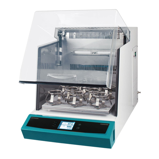
Page 16: Structure
Structure (1) Door cover and Handle You can monitor the inner samples without opening the door during operation. (2) Gas Spring Door can stay opened for the user’ convenience when sample replacement. (3) LED Lamp Long lasting less electricity consumption LED is installed to check the inside of the chamber. (4) Temperature Sensor It is Pt 100Ω... - Page 17 (5) Heater Temperature control is up to 80℃ by two 400W pin heaters. (6) Over Temperature Limiter Over temperature limiter is independently configured from the main controller. The inner temperature of the chamber exceeds more than the set temperature, the device cut off the power to the power switch for the secure condition.
- Page 18 Ground part is connected. (13) External Refrigeration Port (IST-3075/IST-4075only) Even if the model such as IST-3075/4075 which has no refrigerator, It can lower the temperature in the chamber by receiving refrigerant from the external refrigerant device such as chiller.
- Page 19 13...
-
Page 20: Installation
(2) Remove the outer container. (3) Before use, inspect the product carefully for any damage that may have occurred during shipping. (4) Report any damage to your local Jeio Tech office or the distributor. Component (1) After unpacking, check the components. -
Page 21: Preparation Before Installation
It is essential that the product to be situated in an area where there is sufficient space for the product. Below figures show the minimum space requirements needed to properly operate and maintain the product. Dimensions (mm) Models IST-3075(R) IST-4075(R) 15... - Page 22 16...
-
Page 23: Environmental Setting
3.3.2 Environmental setting The unit can be operated properly under the following environmental conditions for a long time running without any problem. No direct sunlight on the product Ambient temperature: 5℃ ~ 40℃ (41℉~104℉) Relative humidity not to exceed 80% Altitude not to exceed 2000m (6,562 feet) Connect the product to earth grounded terminals only. -
Page 24: Installation
Installation 3.4.1 Caution for Installation (1) The device is recommended to use under the room temperature and humidity (30°C, 80%RH) do not install it near the Heat devices like a Heater. (2) Have enough space for door opening. (refer to 3.3.1) (3) Please install it on the sturdy surface laboratory and do not throw down or gives a big shock. -
Page 25: Attaching Condensate Drain
3.6 Attaching/Detaching External Refrigeration (IST-3075, IST-4075 Only) Many laboratories are built with central chilling systems. With this in mind Jeio Tech has developed the IST-3075/4075 so that it can be connected to external refrigeration systems. To connect the unit to an external refrigeration source use Ø8mm OD hard-walled tubing, such as nylon or polyethylene. - Page 26 (1) Inserting tubing into fitting Hold the tubing firmly and push it tightly into the fitting. Run the tubing to the external refrigeration source. (2) Removing from fitting Grab the tubing tightly and push towards the incubated shaker as you firmly push the collet release button with two fingers.
-
Page 27: Connection Power
3.7 Connection power JEIOTECH’s Shaking Incubators use a single-phase current. Use a suitable plug as the picture bellow by Identification label. Voltage is the 10% of applied voltage. 220/230VAC 110/120VAC Connect the power with checking the voltage, Phase, • Capacity. Use the ground power for the connection. -
Page 28: Operation
4 Operation 4.1 Controller The controller is consist of the touch screen, LED, membrane. Once the power is supplied, below display is appeared. Power ON indicator Power is supplied. Temperature Control ON Under the temperature controlling. indicator Shaking Control ON Under the shaking controlling. -
Page 29: How To Use The Controller
4.2 How to use the controller Setting is available on the main display. Set RPM Display the setting RPM. Touch the screen, set the RPM. Set Temperature Display the setting temperature. Touch the screen, set the temperature. Set Timer Display the shaking time. Touch the screen, set the timer. In the case of no timer is set, the operating time is displayed. - Page 30 Power Ack In the case of the power is off for the supply faulty reason and the supply is back, the previous operating is back. It is auto restart function. At the time Power-Ack button is appeared on the display. In the case of the shaking was operating, the operating time is appeared on the display with red words.
-
Page 31: Temperature Control
4.2.1 Temperature control Start temperature control Touch the set temperature button on the main display. Setting display is appeared. Set the temperature with touch pad and touch the start button. The temperature control starts. SV and PV is displayed on the main display with green color. (2) Stop the temperature control Touch the set temperature button. -
Page 32: Shaking Control
4.2.2 Shaking Control (1) Start shaking control Touch the Set RPM Button under the shaking stop status. Setting mode is appeared. Set the value on the display and touch the Start button. Shaking control starts. SV/PV rpm is changed to green color. (2) Stop the shaking control. -
Page 33: Shaking Timer
4.2.3 Shaking Timer Timer is only available for shaking. Once the timer is set, the shaking stops after operating the set time and beep is generated. Setting time is on the display once the timer is set and ‘---:--‘ is on the display once the timer is not set. -
Page 34: Alarm And Stop By Force
Timer setting is available for hour:minute. Touch the part you want to change and put the numbers on it. Move out from the setting mode with ESC button. In the case of no touch for 10 seconds, the display changed to the main automatically. ... - Page 35 Temp. Deviation The temperature difference between setting temperature and present temperature is more than the range of the permission. The unit check it once the present value reached to setting value. Once the gap is over the permission range, the alarm is generated. RPM Deviation The rpm difference between setting rpm and present rpm is more than the range of the permission.
- Page 36 Alarm is not effective if Sound Off is set on the General Setting. Deviation Alarm is not effective once the present value reaches to the setting value. (set time, in permission range) Deviation alarm is initialized under the below situation. ...
-
Page 37: General Settings
4.2.4.2 Faults Fault Alarm stops the unit and inform it to the user when the unit need forced stop for the protection. Fault alarm are over-temp protection, Load Unbalance, Door Open, Sensor Fault, Over Current. General Settings Set the general operating. Touch General Setting button and below setting menu is appeared. Touch the ‘<’... -
Page 38: System Settings
System Settings Set the main variable that affects on the unit. Please read the manual carefully before setting the system. Touch the System setting button on the home display, below clauses are arranged. Control Deviation Set the deviation limit range. Temperature setting and rpm setting are Limit available. -
Page 39: External Start/Stop Key
4.4.2 External Start/Stop Key External Start/Stop button is on the control penal as membrane button. It generates start and stop. Set the applying range of it. Only Shaker The button only works for shaker’s start/stop. Only Incubator The button only works for incubator’s start/stop. Shaker Incubator The button only works for shaker and incubator’s start/stop. - Page 40 Touch the temperature on Set Temp. and put the desired temperature on it and operate the unit. Wait until the actual temp reaches to the setting temp. Once the actual temp reaches to the setting temp, touch the calibrated temp and put the temperature from the external sensor. Touch the confirm for the saving.
- Page 41 Once the door is opened or the temperature is out of range, the temperature control is stopped. The calibration is operating on various points so it limits the calibrating that is our of the logic. The result of the calibration is on the uncalibrated and calibrated. Uncalibrated means the value ...
-
Page 42: Auto Tuning
4.4.3.3 Touch Screen Calibration Touch penal coordinate could be in the problem for the reason of the older unit and the problem in the unit. The unit has a touch screen coordinate function. Touch the “+” on the screen three time s. And repeat it two times. -
Page 43: Reset
4.4.6 Reset Initialize the changed value to the factory value. Temperature Calibration Initialize the calibration value. RPM Calibration Initialize the calibration value. Auto Tuning Initialize the calibration value. Touch Screen Initialize the calibration value. Operating Parameters Initialize the calibration value. Factory Default Initialize the calibration value of all parts. -
Page 44: Glass Fuse
4.5.2 Glass Fuse In the case of the over current generating, the fuse is cut and the power is down. 38... -
Page 45: Maintenance
● power ● Power code ● Exterior cleanliness ● Drain connection ● Outside refrigeration system connection (IST-3075/IST-4075) Incubator temperature actual ● temperature difference ● Auto Tuning Temperature setting ● Temperature correction ● Actual temp. / Display temp. correction ●... -
Page 46: Cleaning
5.2 Cleaning (1) After disconnect the power cord, clean the machine with soft and dried towel. Regarding the un-removable point, clean the polluted area only by towel with alcohol solvent (methanol, ethanol) which has low boiling point. (2) Do not use Acid solution, sharp one, soapy water, detergent and hot water. It makes the machine discolored. -
Page 47: Air Filter Cleaning (Ist-3075R/Ist-4075R)
5.3 Air filter cleaning (IST-3075R/IST-4075R) Step 1: Put power switch and turn the machine off. Step 2: Loosen the bolt that located in edge of condenser cover Step 3: Disassemble condenser cover Step 4: Disassemble air filter which is combined with condenser cover. Step 5: Vacuum or clean the air filter with the water. -
Page 48: Fuse Replacement
There is extra fuse 2pcs in socket case inside. If you need additional fuse, ask it to sales team or seller. Current Model Voltage Fuse (A) Fust Cat. No. consumption(A) 120VAC, 60Hz 00CDE0005543 IST-3075 230VAC, 50/60Hz 00CDE0005544 120VAC, 60Hz 10.1 00CDE0005542 IST-4075 230VAC, 50/60Hz 00CDE0005544... - Page 49 Caution to Electrical shock. Before replace the fuse, turn the machine off and check the power connection again. If the power is connected, serious injury or death can be occurred. Step 1: Press power switch and Power off Step 2: Connect (-) screw driver to fuse holder Spin the fuse holder counterclock wise 50 ˚...
-
Page 50: Troubleshooting
6 Troubleshooting 6.1 Stop during the operating Display Description Solution Message Check the set on the analog over temperature regulator and the operating. Temperature Analog over temperature regulator Restart after temperature is inside of the Limit is active. range. Vibration is generating and the Load normal shaking is not available. -
Page 51: Another Problem And Solution
6.2 Another problem and solution Trouble Probable Cause & Solution ① Check the power plug connection to the socket ② Check if the circuit breaker is operated ③ The equipment is not When the fuse is short circuited, replace new one as enclosed. ④... - Page 52 ① If there is extremely intense vibration of the machine than usual during operation, check the horizontality. If you need, please adjust horizontality according 3.4.2 ② If there is extremely intense vibration of the machine and shaking speed is slow down, check the sample location and relocate the samples harmoniously ③...
-
Page 53: Accessories
7 Accessories Mountable maximum quantity 7.1.1 Universal Platform + Flask Clamp Model IST-3075 series IST-4075 series Flask Clamp 50ml 100ml 250/300ml 500ml 1,000ml 2,000ml 2,800ml 7.1.2 Universal Platform + Plastic Flask Clamp Model IST-3075 series IST-4075 series Flask Clamp 50ml... -
Page 54: Universal Platform + Funnel Clamp
7.1.3 Universal Platform + Funnel Clamp Model IST-3075 series IST-4075 series Funnel Clamp 250ml 500ml 1,000ml 2,000ml 7.1.4 Universal Platform + Microplate Holder Model IST-3075 series IST-4075 series Type Single Tower Flat A(large) Flat B(small) 7.1.5 Universal Platform + Test Tube Rack... -
Page 55: Spring Wire Rack + Flask
7.1.6 Spring Wire Rack + Flask Platform IST-3075 series IST-4075 series Flask 50ml 100/125ml 250/300ml 500ml 1,000ml 2,000ml 2,800ml ※ About the right position for mounting maximum quantity of Accessories, please visit Jeio Tech website or contact our office and distributor. -
Page 56: S/W
8.0 S/W 8.1 Monitoring Program installation (1) Put the installation CD on the CD-ROM drive then the program is operated automatically. Click the “Next” button go to the License Agreement. (2) Check the details and click the “I agree”. (3) Click the “Install” and install the program. 50... - Page 57 (4) Once the program is installed, below window is up and JeioTechSoft icon is generated on the background. Check the Run JeioTechSoft 2.0.0.5 or double click the icon then the program starts. 51...
-
Page 58: Communication Protocol
Communicatioin Reference : http://www.modbus.org/docs/Modbus_Application_Protocol_V1_1b3.pdf 8.2.1 Physical Layer Communication port : RS-232C /USB 8.2.2 Model System number ITEM System Number System Model Number 1611H Shaking incubator IST-3075 1612H Shaking incubator IST-3075R Incubated Shaker 1613H Shaking incubator IST-4075 1614H Shaking incubator IST-4075R 8.2.3 Modbus Protocol Address Definition... - Page 59 MOD_SYS_LAM W/S, R/I lamp auto onoff P_AUTO MOD_AUTO_R W/S, R/I system auto restart ESTART MOD_TEMP_DE temp devi min ~ W/M, R/I temperature deviation temp devi max MOD_TEMP_DE W/S, R/I 0 ~ 3599 temp devi alarm time VI_ALARM MOD_RPM_DE rpm devi min ~ W/S, R/I rpm deviation rpm devi max...
-
Page 60: Modbus Protocol Description
8.2.4 Modbus Protocol Description Command Description Modbus function System boot beep Write code Beep Beep generating data Data System key beep Return the unit name Modbus function code Upper Lower MOD_SYS_NAME Refer to System Return data address Model num number Modbus Return the firmware MOD_SYS_VER... - Page 61 modbus function code return addres uppe lower data lamp auto flag MOD_SYS_LAMP_AU Automatic lamp on setting modbus function lamp auto code data lamp auto data modbus function code return addres uppe lower data MOD_AUTO_RESTAR auto run flag Auto run setting modbus function auto run code...
- Page 62 code data addres rpm devi modbus function rpm devi min ~ value code value modbus function code return addres data rpm devi alarm MOD_RPM_DEVI_ALAR rpm devi alarm time modbus function value 0 ~ 3599(sec) code value modbus function code return data address ext key value...
- Page 63 modbus function 0 ~ 1 code return data addres time MOD_SHAKER_TIME shaker set time modbus function 0 ~ 1 value code 3599940L(min) value modbus function 0 : shaker timer code MOD_SHAKER_TIME_ONO shaker timer on/off data 1 : shaker timer data modbus function 0 : incubator stop MOD_INCUBATOR_RUN_S...
- Page 64 slave temp silent load sk load temp devi hold hold devi warn auto sens door door mute refrig warn warn open error silent incubat connec lamp timer shaker operation disp pos er on/o on/off op_flag op_flag sys op modbus function code 1: message clear MOD_WARN_ACK warn message clear...
-
Page 65: Appendix
9.0 Appendix 9.1 Technical Specifications MODEL IST-3075 IST-3075R IST-4075 IST-4075R Amb.-15 (Min. Amb.-15(Min. Range Amb.+5~80℃ Amb.+5~80℃ +15)~80℃ +15)~80℃ Accuracy ±0.1℃ in flask at 37℃ Temperature Uniformity ±0.5℃ in flask at 37℃ Refrigerator (Hp) 1/6Hp 1/6Hp Sensor Type Pt 100Ω Motion... - Page 66 (mm) Internal 410×410×320 510×510×320 (W×D×H) (mm) Overall (W×D×H) 440 x 785×510 540 x 890×510 (mm) Net Weight (Kg) Electric requirements(230V) 50/60Hz, 4A 50/60Hz, 5.5A 50/60Hz, 4A 50/60Hz, 5.5A Cat. No. Electric requirements(110V) 60Hz , 7.5A 60Hz ,10.1A 60Hz , 7.5A 60Hz ,10.1A Cat.
-
Page 67: Circuit Diagrams
9.2 Circuit Diagrams 9.2.1 IST circuit diagram 9.2.2 External refrigeration system (IST-3075/IST-4075) 9.2.3 Internal refrigeration (IST-3075R/IST-4075R) 61... -
Page 68: Disposing Of Products
2. Please contact your local governing body for regulations regarding disposal of electrical, electronic, metal (brass, aluminum, steel and stainless steel), refrigeration and rubber components. Jeio Tech recommends the user find a local scavenger or laboratory equipment recycler to properly dispose of the unit and its components. -
Page 69: Warranty Exception
9.4.2 Warranty exception Customer can’t get free warranty service in case of as below. If the product is broken due to the user’s fault. • • If the product is broken due to improper operation or storage. • If the product is broken due to improper modify or repairing. •... - Page 70 The Americas (U.S.A. Branch) 19 Alexander Road, Unit #7. Billerica, MA 01821-5094, U.S.A. Tel: +1 781 376 0700 E-mail: info@jeiotech.com FAX: +1 781 376 0704 Europe (U.K. Branch) Unit 3, Tower Industrial Park, Chalgrove, Oxfordshire, OX44 7XZ, United Kingdom Tel: +44 1865 400321 E-mail: labcompanion@medlinescientific.com FAX: +44 1865 400736 China (Shanghai Branch)
Need help?
Do you have a question about the IST-3075 and is the answer not in the manual?
Questions and answers