Advertisement
DualMount: Quick Install
• For surveillance of one area with two sensor modules (in particular, for day and night)
• All available sensor modules (S14D or S15D) can be installed in the DualMount
• Concealed cabling, weatherproof from -30 to +60 °C (IP65)
• Suitable for ceiling installation, with a 25° tilt of the lenses
Installation
Before installing the sensor modules, make sure that the sensor cables will reach the intended mounting position without placing a strain
on the cables. Separate the sensor modules from the sensor cables before installing the modules.
Further information on the individual camera connectors can be found in Section 2.2.1, "Overview Of Cable Connections" of the S14/S15
camera manuals. Install the base module as described in Section 2.3.1
1. Prepare opening
Prepare an opening at the desired mounting position of the SurroundMount
that is large enough (diameter about 30 to 40 mm) to allow the sensor cables
to pass through so that you can connect them.
2. Lead the sensor cables through the opening
Lead the sensor cables through the opening in the ceiling and allow them to
protrude through (the longer they extend, the easier the installation).
3. Attach the hinged ferrites
Attach one hinged ferrite to each sensor cable (maximum distance to the
connector 10 cm).
4. Select mounting type
Select the appropriate mounting type. Depending on the material and the
thickness of the mounting surface, you can mount the DualMount
directly to the ceiling using the five stainless steel wood screws (item
•
1.6) with or without the dowels (item 1.7).
•
to the ceiling (max. thickness 12 mm) using the backing plate (item 1.2)
and the five stainless steel Allen screws (item 1.8). To do this, you have
to push the screws through the ceiling and tighten them to the backing
plate positioned to the back of the ceiling.
5. Set dowels or prepare screw holes
Depending on the desired mounting type, you either set the dowels or prepare
screw holes (for the backing plate). In the second case, you can either use
the drilling template provided at the end of this document or use the backing
plate with its five threaded bushings as a drilling template.
6. Mount the housing
Place the seal (item 1.3) on the SurroundMount housing (item 1.1). Attach the
housing with or without dowels (item 1.7) to the ceiling using the stainless
steel wood screws (item 1.6). When using the backing plate (behind ceiling
boards or roof linings) use the stainless steel Allen screws (item 1.8). You will
need a crosstip screwdriver for the wood screws; for the Allen screws you
will need the 3 mm Allen wrench provided in the package.
7. Connect sensor cables
Connect a sensor cable to each sensor module (one cable through each
opening of the housing). Insert the sensor cable in the socket of the module,
attach the bayonet catch and turn it to the right until it clicks into place.
8. Attach sensor modules
Make sure that the MOBOTIX lettering on the front of the sensor module is
pointing to the "9-o'clock position" as shown in the figure. Turn the sensor
module with the black module wrench (provided with the S15D) to the right
until it reaches the stop.
9. Secure sensor modules
Tighten the two set screws on the underside of the housing to secure each
of the sensor modules. To do this, use the provided 1.5 mm Allen wrench.
Warning: Do not overtighten the screws (plastic housing!).
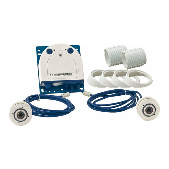
Delivered Parts
1.9
1.8
MOBOTIX AG • D-67722 Langmeil • Tel: +49 6302 9816-0 • Fax: +49 6302 9816-190 • www.mobotix.com
1.1
1.2
1.3
1.6
1.4
1.7
1.5
Day/Night Mount For
Two S14D/S15D Sensor Modules
Max. 10 cm!
Backing plate
Ceiling
Seal
Item
Number
1.1
1
Housing
1.2
1
Backing plate
1.3
1
Seal
1.4
1
Allen wrench 1.5 mm
1.5
1
Allen wrench 3 mm
1.6
5
Stainless steel wood screws 4x40
1.7
5
Dowels 6 mm
1.8
5
Stainless steel Allen screws M4x30
1.9
1
Removal tool
The HiRes Video Company
Ceiling
Seal
Part Name
Advertisement
Table of Contents

Subscribe to Our Youtube Channel
Related Manuals for Mobotix MX-OPT-FM-PW

Summary of Contents for Mobotix MX-OPT-FM-PW
- Page 1 Backing plate Seal Allen wrench 1.5 mm Allen wrench 3 mm Stainless steel wood screws 4x40 Dowels 6 mm Stainless steel Allen screws M4x30 Removal tool MOBOTIX AG • D-67722 Langmeil • Tel: +49 6302 9816-0 • Fax: +49 6302 9816-190 • www.mobotix.com...
- Page 2 25°. The DualMount can also be installed outdoors, e.g., under eaves, bridges, etc. Replacing Sensor Modules All MOBOTIX sensor modules can be used with the DualMount. To replace a sensor module you need the removal tool, which is included with the delivered parts.
Need help?
Do you have a question about the MX-OPT-FM-PW and is the answer not in the manual?
Questions and answers