
Summary of Contents for Achronix PCIe Accelerator-6D Card
- Page 1 PCIe Accelerator-6D Card User Guide (UG074) Speedster FPGAs Speedster FPGAs www.achronix.com...
- Page 2 Copyright © 2017 Achronix Semiconductor Corporation. All rights reserved. Achronix, Speedcore, Speedster, and ACE are trademarks of Achronix Semiconductor Corporation in the U.S. and/or other countries All other trademarks are the property of their respective owners. All specifications subject to change without notice.
-
Page 3: Table Of Contents
Achronix CAD Environment (ACE) Software ........ - Page 4 Miscellaneous Interfaces ........... 31 Chapter - 5: PCIe Accelerator-6D Card Clocking ......33 Chapter - 6: Board Power Supplies .
-
Page 5: Chapter - 1: Pcie Accelerator-6D Kit Overview
Chapter - 1: PCIe Accelerator-6D Kit Overview Achronix PCIe Accelerator-6D Board Figure 1: PCIe Accelerator-6D Kit Contents The Achronix PCIe Accelerator-6D kit contents are as follows: One PCIe Accelerator-6D board Two micro-USB cable PCIe Accelerator-6D Quick Start User Guide Achronix CAD Environment (ACE) license... -
Page 6: Fpga
PCIe Accelerator-6D Card User Guide (UG074) The PCIe Accelerator-6D's four QSFP+ modules support either four 40 gigabit Ethernet ports or sixteen 10 Gigabit Ethernet ports using breakout cables giving a total bandwidth of 160 Gbps. The card also supports PCI Express Gen3 by 8, thus providing 64 Gbps bandwidth. -
Page 7: Achronix Cad Environment (Ace) Software
Board schematics can be made available upon signing an NDA with Achronix. Achronix CAD Environment (ACE) Software Achronix provides ACE software together with an Achronix-optimized version of Synplify-Pro from Synopsys (a node-locked or floating version of the license is needed to use the ACE software for development). See... - Page 8 PCIe Accelerator-6D Card User Guide (UG074) Save www.achronix.com Speedster FPGAs...
-
Page 9: Chapter - 2: General Description
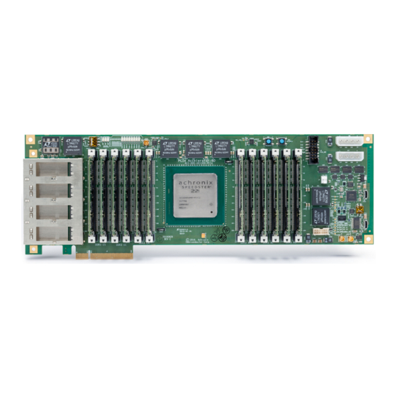
PCIe Accelerator-6D Card User Guide (UG074) Chapter - 2: General Description PCIe Accelerator-6D Board The development board has a PCIe form-factor having a dimension of Length:310 mm × Width:97.5 mm. It also has dedicated power connectors.The figure PCIe Accelerator-6D Board Details (see page 9) below shows the PCIe Accelerator-6D board with many of the key components annotated. -
Page 10: In-System (Plug-In) Mode
PCIe Accelerator-6D Card User Guide (UG074) Figure 4: PCIe Accelerator-6D Board Connected in Standalone Mode In-system (Plug-in) Mode The PCIe Accelerator-6D board is inserted into a PCIe Gen3 ×8 slot of a PC. In addition to the capabilities highlighted in the standalone mode, data traffic can be supplied over the PCIe interface in this mode, assuming the PCIe interface of the FPGA is configured appropriately. -
Page 11: On-Board Memory
PCIe Accelerator-6D Card User Guide (UG074) Figure 5: PCIe Accelerator-6D Board Connected in In-system Mode Note Power must still be provide to the board via an external power supply rather than the PCIe connector and the dedicated power connectors on the board. -
Page 12: On-Board Temperature Sensor
Achronix has configured the SerDes and the I/O at specific pins on the HD1000 device. This configuration must maintain during any changes made to the design hosted in the FGPA. Achronix provides a template for ACE to avoid inadvertent changes to the configuration. The clocking structure implemented on the board must also be maintained during any design changes. -
Page 13: Chapter - 3: Development Environment Setup
(UG002) provides detailed information about acquiring and installing ACE and Synplify Pro licenses and software. A download account is required in order to download the software and request a license. Below is a quick summary of steps to install the Achronix software and licenses: From https://downloads.achronix.com... - Page 14 PCIe Accelerator-6D Card User Guide (UG074) Figure 6: Standalone Board Connections Connecting the Host PC Based on the system requirements, the following are the connections needed to the host PC: Connect the supplied micro-USB cable the to the "USB Connector for FTDI" (see figure:...
-
Page 15: In-System Mode
PCIe Accelerator-6D Card User Guide (UG074) In-system Mode For in-system mode, plug the Accelerator-6D board into an available PCIe ×8 slot of the host PC. Make sure the adjacent slot is also vacant to accommodate the clearance requirements for the component side of the board. -
Page 16: Getting Started
PCIe Accelerator-6D Card User Guide (UG074) Getting started Power Sequencing The power sequencing on the board is pre-configured and is controlled by Linear Technology's LTM2987 power system manager. After connecting the power supply and the POWER GOOD LED (DS3000) is steady green, the board is fully powered up and has initialized all the components in the right order. -
Page 17: Connecting The Board To The Host Pc And Running The Application
Once the FPGA is programmed and the CONFIG_DONE LED light is green, the configuration has successfully completed, and the FPGA has transitioned to user mode. At this point, run any application as desired. For more details refer to the board PCIe Accelerator-6D Card Quick Start User Guide Bitstream Programming and Debug Interface User Guide Speedster FPGAs www.achronix.com... -
Page 18: Chapter - 4: Interfaces
PCIe Accelerator-6D Card User Guide (UG074) Chapter - 4: Interfaces There are various interfaces available on the HD1000 FPGA and the Accelerator-6D board. These interfaces are discussed in more detail in the following sections: Networking and Communications Interface (see page 19) -
Page 19: Networking And Communications Interface
PCIe Accelerator-6D Card User Guide (UG074) Networking and Communications Interface The four QSFP ports provide a primary high-speed networking data interface for the board, enabling the 10G /40G capabilities of HD1000. For the data path, the four 40G QSFP ports together provide a total duplex bandwidth of 320 Gb/s bandwidth (160 Gb/s transmit and 160 Gb/s receive). - Page 20 PCIe Accelerator-6D Card User Guide (UG074) QSFP Module Pin Name QSFP CH No./HD1000 SerDes No. Pin on HD1000 (U1) R_MID_TX1_N R_MID_TX1_P R_MID_TX2_N R_MID_TX2_P R_MID_TX3_N R_MID_TX3_P R_MID_TX4_N R_MID_TX4_P CH 1 16 - 19 R_MID_RX1_N R_MID_RX1_P R_MID_RX2_N R_MID_RX2_P R_MID_RX3_N R_MID_RX3_P R_MID_RX4_N R_MID_RX4_P...
- Page 21 PCIe Accelerator-6D Card User Guide (UG074) QSFP Module Pin Name QSFP CH No./HD1000 SerDes No. Pin on HD1000 (U1) L_MID_RX1_N L_MID_RX1_P L_MID_RX2_N L_MID_RX2_P CH 2 24 - 27 L_MID_RX3_N L_MID_RX3_P L_MID_RX4_N L_MID_RX4_P LEFT_TX1_N LEFT_TX1_P LEFT_TX2_N LEFT_TX2_P LEFT_TX3_N LEFT_TX3_P LEFT_TX4_N LEFT_TX4_P...
-
Page 22: System Interfaces
PCIe Accelerator-6D Card User Guide (UG074) System Interfaces The Accelerator-6D board has the following system interfaces: PCI Express (see page 22) USB (see page 24) JTAG (see page 25) PCI Express A PCIe connector is available for plugging the card into a host PC where the data is provided over the interface. - Page 23 PCIe Accelerator-6D Card User Guide (UG074) Signal Name SerDes No Pin on HD1000 (U1) Pin on PCIe ×8 Finger (J2) PCIE0_RX3_P PCIE0_RX3_N PCIE0_TX3_P PCIE0_TX3_N PCIE0_RX4_P PCIE0_RX4_N PCIE0_TX4_P PCIE0_TX4_N PCIE0_RX5_P PCIE0_RX5_N PCIE0_TX5_P PCIE0_TX5_N PCIE0_RX6_P PCIE0_RX6_N PCIE0_TX6_P PCIE0_TX6_N PCIE0_RX7_P PCIE0_RX7_N PCIE0_TX7_P PCIE0_TX7_N SERDES_BOT_REFCLK_0_P –...
-
Page 24: Usb (J7, J8)
PCIe Accelerator-6D Card User Guide (UG074) Signal Name SerDes No Pin on HD1000 (U1) Pin on PCIe ×8 Finger (J2) SERDES_BOT_REFCLK_0_N – USB (J7, J8) There are two USB connectors on the board, J7 and J8. The USB (J7) port can be used to communicate between the HD1000 FPGA and the host PC vial an an on- board auxiliary UART FTDI chip (U19), which provides a USB to asynchronous serial data transfer interface. -
Page 25: Jtag (J6)
(WC) and northwest (WN) of HD1000 FPGA. The HD1000 drives the memory signals using dedicated GPIO. Achronix provides an ACE template to correctly allocate these I/O pins. For the complete list of DDR3 signal mappings to HD1000 FPGA pin, refer to... -
Page 26: User Interfaces
PCIe Accelerator-6D Card User Guide (UG074) Figure 9: Accelerator-6D Rev C SODIMM sockets The following memory configurations are supported: Single rank - single slot Dual rank - single slot Dual rank - dual slot User Interfaces The following interfaces can be used to configure and drive the board, connect cables, review status of the board, and perform other functions related to development work. -
Page 27: Ftdi Cli
(CLI) window on the development PC to download and configure the HD1000. For more details on programming the HD1000 FPGA using the Achronix STAPL Player, refer to the Bitstream Programming and Debug Interface User Guide - Chapter 4: Using the Achronix STAPL Player. - Page 28 PCIe Accelerator-6D Card User Guide (UG074) ACE GUI for Bitstream Programming Figure 10: ACE GUI for Register Access via JTAG Figure 11: www.achronix.com Speedster FPGAs...
-
Page 29: Smp Connectors
PCIe Accelerator-6D Card User Guide (UG074) Figure 12: ACE GUI for Real-time Design Debug Figure 13: ACE GUI for Hardware Demo SMP Connectors Speedster FPGAs www.achronix.com... -
Page 30: Leds
PCIe Accelerator-6D Card User Guide (UG074) SMP Connectors There are three SMP connectors on the board that can be used for various clocking functions (see the figure, PCIe Accelerator-6D Board Details) (see page 9) . These are connected to the HD1000 as shown in table below. -
Page 31: Switches
PCIe Accelerator-6D Card User Guide (UG074) Switches There are two push-button switches (SW1 and SW2) and two DIP switches (SW10 and SW3000) on the board (see the figure, PCIe Accelerator-6D Board Details) (see page 9) . The following table lists the switches and... - Page 32 PCIe Accelerator-6D Card User Guide (UG074) Net Name Pin 8 – Pin 9 – Pin 10 Pin 11 – Pin 12 – www.achronix.com Speedster FPGAs...
-
Page 33: Chapter - 5: Pcie Accelerator-6D Card Clocking
PCIe Accelerator-6D Card User Guide (UG074) Chapter - 5: PCIe Accelerator-6D Card Clocking The Accelerator-6D board has an on-board IDT frequency synthesizer U12 (8T49N287) which provides the necessary reference clocks to the HD1000 FPGA PLL clock banks on the four corners and the bottom select SerDes which connect to the four QSFP ports. -
Page 34: Chapter - 6: Board Power Supplies
PCIe Accelerator-6D Card User Guide (UG074) Appendix: Board Power Supplies Power Regulator Component (Component Number) Power Rail (Component Number) VCC_1V0_1 LTM4677 (U52) VCC_1V0_2 (a) LTM4677 (U53) VCC_1V0_2 (b) LTM4677 (U58) VCC_1V5_2 (DDR_VDD) LTM4677 (U51) VCC_1V5_1 (DDR_VDD) LTM4677 (U50) VCC_3V3 LTM4633 (U34) - Page 35 PCIe Accelerator-6D Card User Guide (UG074) Power Regulator Component (Component Number) Power Rail (Component Number) DDR3 SODIMM WS Slot 1 (J20) / Slot 0 DDR_WS_VREF/VTT LTC3617 (U3) 0.75 (J21) Heatsink Fan Header (J9) Heatsink Fan F-5010HH12B III Speedster FPGAs www.achronix.com...
-
Page 36: Chapter - 7: Miscellaneous Diagrams And Figures
PCIe Accelerator-6D Card User Guide (UG074) Appendix: Miscellaneous Diagrams and Figures Figure Note I C Address is 7 bits plus a read/write bit. Board Device, Power and I C Map Figure 15: www.achronix.com Speedster FPGAs... -
Page 37: Revision History
PCIe Accelerator-6D Card User Guide (UG074) Revision History Version Date Description March 20, 2017 Initial Achronix release. Added I C Header (J3) Pin Connections (see page 31) table to the cellaneous Interfaces (see page 31) section March 23, 2017 Fixed broken reference links...