Table of Contents
Advertisement
Quick Links
Advertisement
Table of Contents

Related Manuals for Luneau Technology Briot emotion2

Summary of Contents for Luneau Technology Briot emotion2
- Page 1 Instruction Manual...
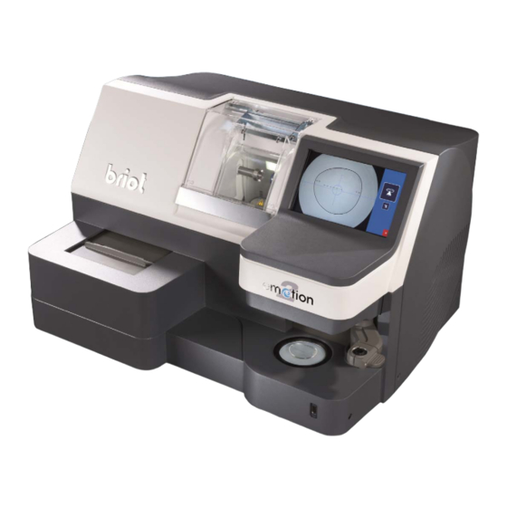
- Page 2 You have purchased an edger, and the entire team at Briot, a brand of the Luneau Technology Group, would like to thank for placing your trust in us. emotion2 or perception2 edger is a laboratory machine designed for opticians and is used for carrying out operations such as creating and selecting jobs, centering and blocking spectacle lenses, and edging and drilling lenses.
- Page 3 RAPHIC CODES Different graphic codes have been used in this manual to allow the user to distinguish between different types of information and easily spot the items which demand special attention (e.g. safety-related items). The table below lists all the codes and describes them: 1: D ABLE ESCRIPTION OF THE PICTOGRAMS...
- Page 4 Waste Electrical and Electronic Equipment (applicable in the European Union and in European countries using a selective waste collection system) This symbol affixed to the product or to its packaging indicates that the product will not be treated like household waste. Instead, it must be delivered to the designated collection point where electric and electronic equipment may be recycled.
-
Page 5: Table Of Contents
\\Table of contents INSTALLATION Drilling Positioning of drilling holes Unpacking the machine 1.8 Limits of hole positioning Warning Limits related to the thickness of the lens Procedure Shape creator function Removing the shipping rails 1.10 Presentation Conditions Procedure Procedure Blocking / centering system Preparing the bench 1.11 Main blocking screen Machine dimensions... - Page 6 \\Table of contents Hints Enabling size compensation according to the bowing/ flattening of the frame Replacement table for standard parts Activating the dual JOB function Adjustments 5.114 Configuring the OMA Presentation of the settings menus access screen Saving the new configuration Screen description Configuration of Communication Access / Exit...
- Page 7 REVISION FOLLOW-UP Revision 00 Page New/Modified Item...
- Page 8 1 INSTALLATION...
-
Page 9: Unpacking The Machine
Installation...Unpacking the machine 1.1 UNPACKING THE MACHINE 1.1.1 W ARNING Ensure that the machine is placed in accordance with the TOP and BOTTOM signs on the box. Place the machine on a flat and stable surface. 1.1.2 P ROCEDURE Follow the steps below to unpack the machine: #1 Place the machine on the floor in its packing with the help of another person. - Page 10 Installation...Unpacking the machine #1&2 Keep the case and the tubes near machine. Illustration 1-1: Unpacking the machine...
-
Page 11: Removing The Shipping Rails
Installation...Removing the shipping rails 1.2 REMOVING THE SHIPPING RAILS 1.2.1 C ONDITIONS The machine is placed on the workbench. There is enough space around the machine. 1.2.1.1 P ROCEDURE To remove the shipping rails, follow the procedure below: #1 With the help of a second person, tip the machine gently to the rear in order to gain access to the 4 rail fixing screws. -
Page 12: Preparing The Bench
Installation...Preparing the bench 1.3 PREPARING THE BENCH 1.3.1 M ACHINE DIMENSIONS The following illustrations show the machine dimensions. 747,3 mm D = 600 mm Illustration 1-3: Edger dimensions Height = 455 mm Width = 747,3 mm Depth = 600 mm ... -
Page 13: Water Connections
Installation...Water connections 1.4 WATER CONNECTIONS 1.4.1 S PECIFICATIONS 1.4.1.1 G ENERAL Water intake with a stop-valve fitted with a 20 x 27 mm female connector and a filter seal. This stop-valve must be reserved for the machine and placed at a maximum of 80 cm from the place provided for the machine. -
Page 14: Procedure
Installation...Water connections 1.4.2.2 P ROCEDURE Flow chart To connect the water supply to the edger and fit the pipes, follow the procedure below: #1 Check that the machine is switched off: On/Off switch OFF and mains plug disconnected. #2 Check that the water supply is closed. #3 Ensure that the machine is level =>... - Page 15 Installation...Water connections As shown... => Level! Pump power connector => DIRECT WATER SUPPLY => CLOSED CIRCUIT 1-14...
-
Page 16: Shipping Safeties
Installation...Shipping safeties 1.5 SHIPPING SAFETIES 1.5.1 R EMOVE THE SHIPPING SAFETIES 1.5.1.1 P ROCEDURE Flow chart To remove the different shipping safeties of the edger, comply with the procedure below: #1 Remove the safety assembly (attachment, red spacer and screw) located in the edging chamber using a 5 mm Allen wrench. -
Page 17: Electrical Connections
Installation...Electrical connections 1.6 ELECTRICAL CONNECTIONS 1.6.1 S PECIFICATIONS 2P+T - 16A - 200/240V plug protected by a 30 mA earth-leakage circuit-breaker. The socket must be earthed. 1.6.2 E DGER WIRING 1.6.2.1 P ROCEDURE Flow chart To connect the peripheral equipment to the edger, proceed as follows: #1 Check that the machine is switched off: On/Off switch OFF and mains plug disconnected. -
Page 18: Starting The Edger
Installation...Starting the edger 1.7 STARTING THE EDGER 1.7.1 P ROCEDURE Flow chart To start the edger, proceed as follows: #1 Check that the machine is switched off: On/Off switch OFF and mains plug disconnected. #2 Fit the lens clamping and lens holder adaptors on the shafts. #3 Plug in the machine and switch on (On/Off switch lit). -
Page 19: Precautions For Use
2 PRECAUTIONS FOR USE... -
Page 20: Safety
Precautions for use...Safety 2.1 SAFETY 2.1.1 O PERATOR Read the instructions carefully and always keep the manual near your machine so you can refer to it easily. This is a rotary machine: the wheels are potentially dangerous. Be very careful and keep your hands away from the set of wheels. -
Page 21: Recommendations
Precautions for use...Recommendations 2.2 RECOMMENDATIONS Comply with the machine maintenance messages. Protect the machine's power cords. Contact a Briot technician for all repairs and always order Briot spare parts. Use only products delivered and specified by Briot. ... - Page 22 Precautions for use...Recommendations Edging zone: Before starting the machine, check that the water supply is working (valve open). Make sure that the installation is perfectly water-tight. Change the water in the tank regularly if your machine operates in closed water circuit mode. ...
-
Page 23: Using Your Edger
3 USING YOUR EDGER... -
Page 24: Presentation
Using your Edger...Presentation 3.1 PRESENTATION 3.1.1 P RESENTATION OF THE MACHINE ENERAL ILLUSTRATION The illustration below (Illustration 3-1) is an overall view of the machine (emotion2 or perception2) and shows its main parts. Edging Touch screen chamber ScanForm* Centering/blocking system Illustration 3-1 : Overall view of the edger * On the Perception2 machine, the Scanform is replaced by a map pockets. -
Page 25: Description Of The Stations
Using your Edger...Presentation 3.1.2 D ESCRIPTION OF THE STATIONS The emotion2 or the perception2 is composed of the following components: 3.1.2.1 T OUCH SCREEN The touch screen allows you to: Use emotion2 or perception2. Enter the job data. ... -
Page 26: Presentation Of The Application Screen
Using your Edger...Presentation 3.1.3 P RESENTATION OF THE APPLICATION SCREEN 3.1.3.1 W ORK INTERFACE The screen below (Screen 3-1) is displayed after initializing the equipment at start-up. The screen is organised so that you can follow the steps in logical order. The interface includes 4 tabs giving access to the preparation/production steps of the spectacles. -
Page 27: Visual References
Using your Edger...Presentation 3.1.3.2 V ISUAL REFERENCES 3.1.3.2.1 T YPES OF BUTTONS There are different types of buttons corresponding to the different types of action or information to be entered : N ALL OF THE MENUS The action button: Produces an immediate action or is used to make a selection in a pull-down list. Example : ... -
Page 28: Usual Procedure
Using your Edger...Usual procedure 3.2 USUAL PROCEDURE 3.2.1 J OB CREATION SELECTION 3.2.1.1 C ALLING UP A JOB Press this button Short press: Used to enter a Job number. When the numeric key pad is displayed, enter the job number and confirm it. Long press: Used to access the Jobs database. - Page 29 Using your Edger...Usual procedure Activate the Input tab the calculator appears for entry of a Job Access to Scanform screen Access to jobs base The calculator is displayed to enter a job No. to be loa- ded from the OMA. When the calcula- tor is displayed, a bar code can be...
- Page 30 Using your Edger...Usual procedure Loading a Job: Short press: access to the pattern database Short press: a calculator is opened in order to enter a Job number (if this Job already exists in the Jobs database, this Job is displayed) Loading a Job number from the OMA server: (configurable function) Sending the Job to the OMA server:...
-
Page 31: Calling Up A Job Saved In The Memory
Using your Edger...Usual procedure 3.2.1.2 C ALLING UP A JOB SAVED IN THE MEMORY The numbers of this illustration refer to the step numbers below. Previous page Move down Next page Move up Confirm Return to creation screen Follow the steps below to call up a job saved in the memory: 1 Pressing on the Job selection key ( ) is used to access the com- pete list of saved jobs. -
Page 32: Scanform
Using your Edger...Usual procedure 3.2.2 S CANFORM Create a job Enter the new a job number. Entering the frame data Entering a pattern Select the frame type. Insert the pattern or the demonstration lens that has been blocked on the frame holder NOTE : The lower part of the pattern should push the Select the side(s) to be entered. -
Page 33: Gravitech™ Optical Plotter
Using your Edger...Usual procedure 3.2.3 G RAVITECH ™ OPTICAL PLOTTER 3.2.3.1 L ENS TRACING First draw the frame axis using the tool and the felt-tip pen supplied in the accessory case. Refer to the unpacking guide supplied with your machine. Line centered on lens Illustration 3-3 : Tracing a lens It is possible to configure the side's automatic detection. -
Page 34: Positioning / Start Of Capturing
Using your Edger...Usual procedure 3.2.3.2 P OSITIONING TART OF CAPTURING Place the lens on the support. For greater precision of measurement, the external face of the presentation lens must be in contact with the bearing surface. Support Cupped side of the lens Illustration 3-5 : Positioning the lens Press the Gravitech™... - Page 35 Using your Edger...Usual procedure 3.2.3.2.1 M EASURING THE PRESENTATION LENS OR PATTERN You may position the axis using arrows located on the right of the screen: (1) translation / (2) rotation. Translation of the axis Rotation of the axis Validation of Cancellation of treatment treatment...
- Page 36 Using your Edger...Usual procedure 3.2.3.2.3 D RILLING PLAN You have the possibility to choose automatic detection of holes present on your lens. Measurement with detection of drilling holes Measurement wi- thout drilling holes Screen 3-7 : Measurement launch screen. Once the measurement is completed, you then automatically access the screen enabling: ...
- Page 37 Using your Edger...Usual procedure 3.2.3.2.4 E LIMINATION OF HOLES If you launched Gravitech™ optical centering with the hole detection function and you do not wish to have the holes appear, you may eliminate them as follows: Hole elimination icon Screen 3-10 : Hole elimination screen 3.2.3.2.5 V ISUALIZATION OF THE AXIS TREATEMENT You may conduct a visualization of the axis treatment image, if it exists.
- Page 38 Using your Edger...Usual procedure 3.2.3.2.6 O VERSIZE OF A SHAPE Lens compensation involves applying an oversize or not (defined in the machine settings). You may change the proportional compensation value, using the entry button (2). If no compensation is necessary, simply press the button (1). Screen 3-12 : Lens compensation screen...
-
Page 39: Entering The Bridge Value
Using your Edger...Usual procedure 3.2.3.3 E NTERING THE BRIDGE VALUE After completing the validation (by pressing the key ) , you will be redirected to the main screen. The numeric keypad is displayed automatically in order to enter the bridge value of the frame (by default, the value is 20 mm). -
Page 40: Mirror Function
Using your Edger...Usual procedure 3.2.3.5 M IRROR FUNCTION In case of errors in identification of the nasal side during data entry, it is possible to correct this error by applying a "Mirror" function on the shape. Symmetric copy Reverse the work sides (mirror image) Frame groove Shape change... -
Page 41: Digiform
Using your Edger...Usual procedure 3.2.4 D IGIFORM Press the Digiform tab 3.2.4.1 P RESENTATION The Digiform function is used to change any initial job into a new job. To modify the shape of a pattern, use the functions on the bottom of the screen. Access to ... -
Page 42: Deforming The Shape Of A Job
Using your Edger...Usual procedure 3.2.4.2 D EFORMING THE SHAPE OF A JOB Follow the steps below to modify a shape (Digiform function): 1 Load a Job from the creation tab. 2 Change the shape as desired. (Refer to the Presentation section of the Digiform function) 3 Confirm the modifications and quit the Digiform function. -
Page 43: Pivoting The Shape Of A Job
Using your Edger...Usual procedure 3.2.4.3 P IVOTING THE SHAPE OF A JOB This function is used to pivot the shape to the degree desired. Proceed as follows to pivot a shape: 1 Open the initial saved shape. 2 Press the rotation key. Using the number key pad, enter the desired degree. -
Page 44: Drilling
Using your Edger...Usual procedure 3.2.5 D RILLING To access the drilling menu, press the key 3.2.5.1 P OSITIONING OF DRILLING HOLES Shape center Hole coordinates Drilling diameter Navigation arrows Previous Next hole hole Hole selection Remove a hole Change the diameter value Drill an elon-... - Page 45 Using your Edger...Usual procedure 3.2.5.1.1 P ROCEDURE EMARKS Load a job number (from the JOB tab). Access the Drilling menu (from the Digiform tab). Add a drilling hole. NOTE: This appears at coordinates X=15; Y = 15. Position the hole using the navigation arrows of the zoom or en- ter the values.
-
Page 46: Limits Of Hole Positioning
Using your Edger...Usual procedure 3.2.5.2 L IMITS OF HOLE POSITIONING Whatever the type of hole, it must be drilled in a specific zone which is defined following the diagrams below. The following constraints must be observed: The circle radius beyond which drilling is possible: Min. -
Page 47: Limits Related To The Thickness Of The Lens
Using your Edger...Usual procedure 3.2.5.3 L IMITS RELATED TO THE THICKNESS OF THE LENS The position of the hole and the strength of the lens to be drilled effect the drilling depth. These two parameters can cause non-through holes which must then be finished manually. ... -
Page 48: Shape Creator Function
Using your Edger...Usual procedure 3.2.6 S HAPE CREATOR FUNCTION 3.2.6.1 P RESENTATION This function may be used on a presentation lens that may be partly damaged, or to create an original shape. To access this function, press the key Shape Creator function Screen 3-21 : Access screen to the SHAPE CREATOR function 3.2.6.2 P... - Page 49 Using your Edger...Usual procedure 3.2.6.2.2 S HAPE ENTRY Place points by clicking on the screen. Please click inside the frame shape. As you position the points, the shape will appear on the screen and you will adjust the visual. NOTA : The point being positioned appears in red on the screen. Screen 3-23 : Point-by-point entry screen.
- Page 50 Using your Edger...Usual procedure Then, you will be sent to the frame display screen. At any time, you may return to the Shape Creator screen by clicking on Screen 3-25 : Frame shape display screen. 3-49...
-
Page 51: Blocking / Centering System
Using your Edger...Usual procedure 3.2.7 B LOCKING CENTERING SYSTEM 3.2.7.1 M AIN BLOCKING SCREEN Follow the steps below to block a lens: Enter the blocking/centering tab Position of the pupil (blue cross) Display type Vertical decen- tering (delta or boxing or mix) Max. -
Page 52: Marking Type For Live Blocking
Using your Edger...Usual procedure 3.2.7.2 M ARKING TYPE FOR IVE BLOCKING (All machines except Expression) Centering a lens marked with a frontofo- cometer - The central point must be on the green cross. - The lateral points must be on the horizon- tal line. - Page 53 Using your Edger...Usual procedure Blocker arm Block support Blocker head 3-52...
-
Page 54: Lens Characteristics
Using your Edger...Usual procedure 3.2.7.3 L ENS CHARACTERISTICS The emotion2 is designed to block lenses with the following characteristics: IAMETER Diameter of uncut lens: 30 to 100 mm & The index and colour have no effect on the centering function. NDEX COLOUR The lens treatment, in particular the anti-reflective coating, has no effect on the... -
Page 55: Edging
Using your Edger...Usual procedure 3.2.8 E DGING 3.2.8.1 P RESENTATION Enter the Edging tab Lens materials Select lens Finishing Sub-finishing Launch the ed- ging process Rear safety-bevel Depth/width of Tighten the lens grooving finishing Polishing Front safety-bevel Oversize to boxing width Screen 3-26 : Edging tab general icons. - Page 56 Using your Edger...Usual procedure 3.2.8.1.1 N ORMAL EDGING CYCLE SEQUENCE Once you have started the edging cycle, the following steps follow automatically: (except if the cycles are personalised) emotion2 / perception2 Closing of the lens clamp shaft Lens roughing Lens finishing (Rimless or Bevel) Lens polishing (if selected) Lens safety-beveling (if selected) Lens grooving (if selected)
- Page 57 Using your Edger...Usual procedure 3.2.8.1.2 U SUAL PROCEDURE The following flow chart shows the usual edging procedure. To obtain more information about a step or to see the relevant icons, click on the zone concerned. Create a Job in the creation interface. Change the job shape in the Digiform interface, if desired Drill the job in the Digiform interface, if desired.
- Page 58 Using your Edger...Usual procedure 3.2.8.1.3 I NSERTING EMOVING THE LENS 3.2.8.1.3.1 To place the lens in the edging chamber When all the edging characteristics have been entered, insert the lens in the edging chamber. Always check that the correct clamping adaptors for the job have been fitted. 19 mm diameter adaptors 17/flat adaptors 25 mm diameter adaptors...
-
Page 59: Lens Materials
Using your Edger...Usual procedure 3.2.8.2 L ENS MATERIALS Note : The presence and order of the icons displayed on the screen depend on the job data. CR39 Mineral Polycarbonate Trivex™ High Index Plastic Screen 3-27 : Lens Material Icons 3.2.8.3 T YPES OF LENSES Note : The presence and order of the icons displayed on the screen depend on the job data. -
Page 60: Finishing
Using your Edger...Usual procedure 3.2.8.4 F INISHING Note : The presence and order of the icons displayed on the screen depend on the job data. Grooving Bevel Rimless Screen 3-29 : Finishing Type Icons 3.2.8.4.1 R IMLESS FINISHING Min. height of finished lens = 17.50 mm Front face Rimless Illustration 3-6 : Limits of production of a rimless lens... -
Page 61: Sub-Finishing And Associated Parameters
Using your Edger...Usual procedure 3.2.8.5 S FINISHING AND ASSOCIATED PARAMETERS The following screen is a montage to show all possible sub-finishing. GROOVE BEVEL Manual Auto Screen 3-30 : Sub-finishing type icons Groove/Manual Bevel By selecting this type of finish, you can check and reposition the bevel/the groove during the edging cycle using a special screen which is displayed after the second lens feeling cycle. - Page 62 Using your Edger...Usual procedure 3.2.8.5.1 P RODUCING A JOB WITH RIMLESS FINISHING 3.2.8.5.1.1 Object Produce a job with the following characteristics: Polycarbonate > Normal lens > Rimless finishing > No safety-bevel > Polishing 3.2.8.5.1.2 Procedure To carry out the job described above, proceed as follows: Create a Job in the creation interface.
- Page 63 Using your Edger...Usual procedure 3.2.8.5.2 C OMPLETE A JOB WITH GROOVE FINISHINGS 3.2.8.5.2.1 Object Produce a job with the following characteristics: HI plastic > Normal lens > Grooving > 33% Groove > Front and rear safety-bevel> Polishing Safety-bevel parameters: front depth = 0.20 mm / rear depth = 0.20 mm 3.2.8.5.2.2 Procedure To carry out the job described above, proceed as follows: Create a Job in the creation interface.
- Page 64 Using your Edger...Usual procedure 3.2.8.5.3 P RODUCING A JOB WITH BEVEL FINISHING 3.2.8.5.3.1 Object Produce a job with the following characteristics: Mineral > Fragile lens > 1/2-1/2 bevel > Rear safety-bevel = 0.40 mm > Without polishing 3.2.8.5.3.2 Procedure To carry out the job described above, proceed as follows: Create a Job in the creation interface.
- Page 65 Using your Edger...Usual procedure Mineral lens Fragile type Bevel finishing 50% Bevel Without Without polishing oversize Screen 3-33 : Example of the production of a job with rimless finishing 3-64...
-
Page 66: Safety Bevels
Using your Edger...Usual procedure 3.2.8.6 S AFETY BEVELS No rear face Rear face Rear face Front face No front face Rear face safety-bevel 0.2mm 0.4mm 0.2mm safety-bevel 0.6mm Screen 3-34 : Safety-Bevel Type icons MPORTANT NOTES A safety-bevel can only be made when: - the distance between the apex of the bevel and the front/rear face of the lens is greater than ... -
Page 67: Polishing
Using your Edger...Usual procedure 3.2.9 P OLISHING Note : The presence and order of the icons displayed on the screen depend on the job data. With Without Screen 3-35 : Polishing Icons 3-66... -
Page 68: Special Case
Using your Edger...Special case 3.3 SPECIAL CASE 3.3.1 A PPLYING AN OVERSIZE 3.3.1.1 W If you find that the overthickness applied to the job by default is not suitable, you can decide to apply an oversize which will be applied to the lens to be edged. 3.3.1.2 H 3.3.1.2.1 P RELIMINARY CONDITION... -
Page 69: Edging The Left Lens With Different Parameters From
Using your Edger...Special case 3.3.2 E DGING THE LEFT LENS WITH DIFFERENT PARAMETERS FROM THOSE OF THE RIGHT LENS 3.3.2.1 P RINCIPLE If the left and right lenses of your job do not have the same characteristics, you may modify the edging data from one lens to another using the buttons available in the Edging tab. -
Page 70: Checking A Finishing Before The Lens Is Edged
Using your Edger...Special case 3.3.3 C HECKING A FINISHING BEFORE THE LENS IS EDGED 3.3.3.1 P RINCIPLE You may wish to check the position of the desired finishing - bevel and groove - before beginning the lens edging cycle. ... - Page 71 Using your Edger...Special case 3.3.3.2.2 M ANUAL GROOVE SCREEN Front face developed curve Developed lens profile Re-feeling Groove centre developed curve Displacement Rear face developed curve of the groove Angular forward position Index Lens shape seen Lens section at posi- Displacement from the front tion of index...
-
Page 72: Visualise A Finishing
Using your Edger...Special case 3.3.3.3 V ISUALISE A FINISHING 3.3.3.3.1 S ITUATION You are not sure about the finishing position and wish to visualise it before it is run. 3.3.3.3.2 P ROCEDURE After opening the job and entering the characteristics, proceed as follows: Check that finishing = At the end of the lens feeling cycle, the manual finishing screen is displayed. -
Page 73: Place A Finishing Manually
Using your Edger...Special case 3.3.3.4 P LACE A FINISHING MANUALLY 3.3.3.4.1 S ITUATION You wish to visualise the lens thickness and adjust the finishing position. 3.3.3.4.2 P ROCEDURE After opening the job and entering the characteristics, proceed as follows: Check that finishing = After lens roughing and feeling, the manual finishing screen is displayed. -
Page 74: Produce A Manual Bevel
Using your Edger...Special case 3.3.3.5 P RODUCE A MANUAL BEVEL 3.3.3.5.1 S ITUATION You wish to visualise the lens thickness and adjust the finishing position. 3.3.3.5.2 P ROCEDURE To produce a manual bevel: 1. Load or create a job. 2. - Page 75 Using your Edger...Special case Check that finishing= The manual finishing screen is displayed. By default, the apex of the bevel is positioned at 1/3 of the lens thickness from the front face. Restart of feeling, if necessary [If desired] Move the bevel apex and position it as you wish. [To the rear] [To the front] Move the bevel apex and position it as you wish.
-
Page 76: Produce A Manual Groove
Using your Edger...Special case 3.3.3.6 P RODUCE A MANUAL GROOVE 3.3.3.6.1 S ITUATION You wish to visualise the lens thickness and define the curve and the position of the groove. 3.3.3.6.2 P ROCEDURE To produce a manual groove: 1. Load or create a job. 2. - Page 77 Using your Edger...Special case Check that finishing = - The manual finishing screen is displayed. By default, the middle of the groove is positioned at 1/3 of the lens thichness from the front face. Restart of feeling, if necessary [If desired] Move the finishing and position it as you wish.
-
Page 78: Feel The Lens Again
Using your Edger...Special case 3.3.3.7 F EEL THE LENS AGAIN If the diameter of the lens being felt is too small, the warning message "Lens too small" is displayed and you transfer to the manual finishing screen. You may then feel the lens three times successively. The lens is felt 0.5 mm closer to the interior each time. -
Page 79: Points To Remember
Using your Edger...Points to remember 3.4 POINTS TO REMEMBER Lens Diameter of uncut lens before edging = diameter of 80 mm plus 10 mm of maximum eccentricity, i.e. a diameter of 100 mm without decentering. Thicknesses Maximum thickness at the edge of the uncut (plastic) lens = 18 mm Maximum thickness at the edge of the uncut (mineral) lens = 16 mm Minimum thickness at the centre of the uncut lens = 1.2 mm. - Page 80 Using your Edger...Points to remember Safety-bevel Maximum depth = 0.6 mm in steps of 0.1 mm Retouching with safety-bevel is possible if the value of the retouch is less than 0.2 mm (at Boxing width) Minimum distance between the apex of the bevel and the front/rear face to produce a safety-bevel = 1.6 mm Min.
-
Page 81: Configuration
4 CONFIGURATION... -
Page 82: Presentation Of Configuration Menus
Configuration...Presentation of configuration menus 4.1 PRESENTATION OF CONFIGURATION MENUS 4.1.1 P RESENTATION OF THE CONFIGURATION MENU ACCESS SCREEN 4.1.1.1 S CREEN DESCRIPTION The first user screen provides access to the user technical menus, such as the settings menu and the statistics menu. -
Page 83: Presentation Of The Personalisation Menu Access Screen
Configuration...Presentation of configuration menus 4.1.2 P RESENTATION OF THE PERSONALISATION MENU ACCESS SCREEN 4.1.2.1 S CREEN DESCRIPTION The personalisation menu access screen is shown below: personalisation menu Frame and lens values Adjustment of correction screen setting values General operation Communication parameters Screen 4-2: Personalisation menu access screen 4.1.2.2 A... -
Page 84: Adjustment Of Setting Values
Configuration...Adjustment of setting values 4.2 ADJUSTMENT OF SETTING VALUES 4.2.1 P RELIMINARY REMARKS The machine is factory-adjusted to meet the needs and requirements of the majority of users. Any modifications of the standard setting values can affect the performance of the machine. ... -
Page 85: Limits
Configuration...Adjustment of setting values Adjust the position of the middle of the groove Adjust the depth of the RESET front safety bevel DURING SETTINGS Groove Groove width depth Adjust the depth of the rear To adjust the position default ... -
Page 86: Correction Of Frame And Lens Values
Configuration...Correction of frame and lens values 4.3 CORRECTION OF FRAME AND LENS VALUES 4.3.1 P RELIMINARY REMARKS The machine is factory-adjusted to meet the needs and requirements of the majority of users. Any modifications of the standard setting values can affect the performance of the machine. ... - Page 87 Configuration...Correction of frame and lens values To enter a correction To enter a correction NOT TAKEN INTO for plastic frames for plastic and metal ACCOUNT frames DURING SETTINGS Save the changes Adjustment of setting values To enter a correction To enter a correction for Polycarbonate lenses for High Index lenses To enter a correction...
-
Page 88: Configuration Of General Operating Parameters
Configuration...Configuration of general operating parameters 4.4 CONFIGURATION OF GENERAL OPERATING PARAMETERS 4.4.1 P RESENTATION 4.4.1.1 P RINCIPLE You define the machine's general operating mode. 4.4.1.2 S CREEN DESCRIPTION The setting screen for the machine's general operating parameters is shown below: Compensation of Compensation of Dialog language.... -
Page 89: Configuration Of The Functions
Configuration...Configuration of general operating parameters 4.4.2 C ONFIGURATION OF THE FUNCTIONS 4.4.2.1 S ELECTING THE DIALOG LANGUAGE To select the dialog language, press this button until the desired language is displayed. 4.4.2.2 E NABLING SIZE COMPENSATION ACCORDING TO TEMPERATURE 4.4.2.2.1 P RINCIPLE ... -
Page 90: Saving The New Configuration
Configuration...Configuration of general operating parameters 4.4.3 S AVING THE NEW CONFIGURATION When you quit the screen, the message "Do you wish to save the new configuration?" is displayed. You have three possibilities: Confirm the message: The configuration is taken into account and you return to the personalisation menu access screen. -
Page 91: Configuration Of Communication Parameters
Configuration...Configuration of Communication parameters 4.5 CONFIGURATION OF COMMUNICATION PARAMETERS 4.5.1 P RESENTATION 4.5.1.1 P RINCIPLE You enable or disable the communication functions according to the peripheral equipment connected to the machine 4.5.1.2 S CREEN DESCRIPTION The setting screen for the machine communications is shown below: You are in the To save the settings Communication parameters screen... - Page 92 5 MAINTENANCE...
-
Page 93: Presentation Of Maintenance Menus
Maintenance...Presentation of maintenance menus 5.1 PRESENTATION OF MAINTENANCE MENUS 5.1.1 P RESENTATION OF THE MAINTENANCE MENU ACCESS SCREEN 5.1.1.1 S CREEN DESCRIPTION The first user technical screen gives access to the user technical menus, including Maintenance, as shown in yel- low below: You are in the User Technical menu... -
Page 94: Presentation Of The Maintenance Screen
Maintenance...Presentation of maintenance menus 5.1.2 P RESENTATION OF THE MAINTENANCE SCREEN 5.1.2.1 S CREEN DESCRIPTION The maintenance menus access screen is shown below: You are in the User Main- Emptying the settling tank tenance menu Dressing Changing the lens feeler tip the wheels Degraded mode (linked to the visor) -
Page 95: Displaying The Components
Maintenance...Displaying the components 5.2 DISPLAYING THE COMPONENTS The illustrations below will help you to identify the parts of the edger on which you will be working during main- tenance operations. Visor Lens feeler tip > Cleaning and replacement > Replacement >... -
Page 96: Task List
Maintenance...Task list 5.3 TASK LIST To ensure the performance of your emotion2 or perception2, you must regularly perform some maintenance operations. Maintenance of the Scanform™ unit Cleaning the Scanform™ Replacing a stylus head Replacing the frame clip tubes ... -
Page 97: Maintenance Of The Touch Screen Zone
Maintenance...Maintenance of the touch screen zone 5.4 MAINTENANCE OF THE TOUCH SCREEN ZONE 5.4.1 C LEANING THE TOUCH SCREEN #1 Switch OFF the machine if it is ON. #2 Clean the touch screen gently with a soft, dry lint-free cloth. CAUTION Do not use products such as water or chemical agents. -
Page 98: Maintenance Of The Scanform Unit
Maintenance...Maintenance of the Scanform unit 5.5 MAINTENANCE OF THE SCANFORM UNIT 5.5.1 C LEANING THE CANFORM To clean the Scanform™, proceed as follows: #1 Switch OFF the machine if it is ON. #2 Lift up the stylus head manually. #3 Clean the stylus head with a brush, making sure no dusts enter the Scanform™ unit. #4 Gently blow away any dusts from the Scanform™... -
Page 99: Replacing The Frame Clip Tubes
Maintenance...Maintenance of the Scanform unit 5.5.3 R EPLACING THE FRAME CLIP TUBES To replace the frame clip tubes, proceed as follows: #1 Switch OFF the machine if it is ON. #2 Manually open the Scanform™ and hold it in this position without applying force. #3 Exert horizontal traction on the frame clip tube you want to replace ... -
Page 100: Maintenance Of The Centering/Blocking System Zone
Maintenance...Maintenance of the centering/blocking system zone 5.6 MAINTENANCE OF THE CENTERING/BLOCKING SYSTEM ZONE 5.6.1 C LEANING THE BEARING SURFACE To replace the bearing surface, proceed as follows: #1 Remove any element that may hinder proper execution of the operation (e.g. -
Page 101: Replacing The Main Fuse
Maintenance...Maintenance of the centering/blocking system zone 5.6.3 R EPLACING THE MAIN FUSE To replace a fuse, proceed as follows: CAUTION STRICTLY OBSERVE THE FOLLOWING INSTRUCTIONS. FAILURE TO DO SO CAN BE DANGE- ROUS BOTH FOR THE USER AND THE MACHINE. #1 Switch OFF the machine if it is ON. -
Page 102: Regular Maintenance Of The Edger
Maintenance...Regular maintenance of the edger 5.7 REGULAR MAINTENANCE OF THE EDGER 5.7.1 R EPLACING THE FLEXIBLE LENS CLAMP ADAPTOR PAD 5.7.1.1 P RELIMINARY REMARKS Caution! The lens holder adaptor is serrated and the lens feeler tips are pointed. Make sure that your hands are protected when handling the lens holder adaptor and feeler tip. 5.7.1.2 P ROCEDURE To replace the flexible lens clamp adaptor pad, follow the procedure below:... -
Page 103: Replacing The Mill Bit
Maintenance...Regular maintenance of the edger 5.7.2 R EPLACING THE MILL BIT 5.7.2.1 P RELIMINARY REMARKS It may be necessary to change the mill bit. A change of mill bit may be necessary for the following reasons: Broken bit Worn bit (chips around the holes on the internal side of the lens);... -
Page 104: Hints
Maintenance...Regular maintenance of the edger #5-11 Mill bit Bit replacement screen Chuck nut Spacer Tighten/Loosen the nut Block the rotation with an Allen key or with one turn of the screwdriver! Flat organic lens Diameter > 57 mm 10 00 205 Adjustment of the flush of the mill bit Flush point Illustration 5-4: Replacing the mill bit. -
Page 105: Replacing The Lens Feeler Tips
Maintenance...Regular maintenance of the edger 5.7.3 R EPLACING THE LENS FEELER TIPS 5.7.3.1 P RELIMINARY REMARKS Always contact your Briot representative before replacing the lens feeler tips. 5.7.3.2 P ROCEDURE To replace the feeler tip, follow the procedure below: #5 Hold the holder and immobilise the feeler arm. #6 Insert a screwdriver or an Allen wrench in the hole of the removable feeler tip. -
Page 106: Hints
Maintenance...Regular maintenance of the edger FRAGILE MOUNTING! Place the feeler in the replacement position. Removable lens feeler tip #5, 6, 7, 8 Place the feeler in the position to receive the tool. Confirm and switch automatically to the feeling adjustment screen. -
Page 107: Dressing A Wheel
Maintenance...Regular maintenance of the edger 5.7.4 D RESSING A WHEEL 5.7.4.1 P RELIMINARY REMARKS Dressing the polishing wheel is not recommended. Too frequent dressing of the wheels reduces their working life. 5.7.4.2 P ROCEDURE Follow the steps below to dress a wheel: According to your selection #5 Make sure large adaptors are fitted. - Page 108 Maintenance...Regular maintenance of the edger => Ensure that the dres- sing disc is correctly centered using the in- dentations intended to receive the adaptors. Illustration 5-6: Dressing a wheel 5-107...
-
Page 109: Cleaning / Replacing The Removable Visor
Maintenance...Regular maintenance of the edger 5.7.5 C LEANING REPLACING THE REMOVABLE VISOR 5.7.5.1 P RELIMINARY REMARKS Before undertaking any operation, ensure that the machine is switched off: On/Off switch OFF and mains plug disconnected. 5.7.5.2 R EPLACING THE VISOR 5.7.5.2.1 P ROCEDURE To replace the visor, proceed as described above. - Page 110 Maintenance...Regular maintenance of the edger Outer visor Screw Inner visor #4 or #5 Illustration 5-7: Cleaning and replacing the removable visor 5-109...
-
Page 111: Cleaning The Filters And Water Tank
Maintenance...Regular maintenance of the edger 5.7.6 C LEANING THE FILTERS AND WATER TANK Refer to the document FC00854. 5.7.7 E MPTYING THE WATER TANK 5.7.7.1 P RELIMINARY REMARKS Use a standard discharge pipe with a 20x27 connection. 5.7.7.2 P ROCEDURE To empty the settling tank, follow the procedure below: #1 Fit a discharge pipe on the same side as the valve and connect it to the ... -
Page 112: Hints
Maintenance...Regular maintenance of the edger 5.7.7.3 H INTS If the pump is not activated when you restart the machine after cleaning, open the discharge valve to the minimum to allow the escape of any air which has remained in the pipes. Close the valve before restarting the process. -
Page 113: Handling The Covers
Maintenance...Handling the covers 5.8 HANDLING THE COVERS 5.8.1 R EMOVING THE COVERS 5.8.1.1 W The machine is clamped during transport to ensure maximum stability. To access the internal components, the uncovering operation must only be performed by a technician. 5.8.1.2 H To remove the machine covers, follow the procedure below: #1 Loosen and remove the four fixing screws from the rear cover... -
Page 114: Preventive Maintenance
Maintenance...Preventive maintenance 5.9 PREVENTIVE MAINTENANCE 5.9.1 H INTS You will optimise the working life of your edger by using only Briot spare parts. Change the blocks regularly - every 100 lenses. 5.9.2 R EPLACEMENT TABLE FOR STANDARD PARTS The following table summarises the replacement frequency for standard parts, calculated according to the number of lenses edged. -
Page 115: Adjustments
Maintenance...Adjustments 5.10 ADJUSTMENTS 5.10.1 P RESENTATION OF THE SETTINGS MENUS ACCESS SCREEN 5.10.1.1 S CREEN DESCRIPTION The settings menu access screen is shown below: You are in the User Set- Touch screen adjustment tings menu Feeling adjustment Mineral roughing wheel adjustment Consultation of setting values Scanform adjustment Size adjustment... -
Page 116: Adjusting The Scanform
Maintenance...Adjustments 5.10.2 A DJUSTING THE CANFORM Follow the steps below to adjust the Scanform™. #1 Press on the top of the application screen. Result: The menu access screen is displayed. #2 Press this key #3 Press this key: Result: The Scanform™ starts operating. #4 When the icon appears, equip yourself with the gain adjustment tool ... - Page 117 Maintenance...Adjustments #11 When the icon is displayed, get tool no. 1404185. #12 Ensure that the diameter value of the round shape marked on the tool is the same as the value displayed on the screen. "If the values are the same, go to the next step. "If the values are not the same, enter the values marked on the tool using the ...
- Page 118 Maintenance...Adjustments #20 Position the tool in the frame-holder (Figure 3). Figure 3 #21 Press . Result: The stylus grabs the round pattern and adjustment is started. #22 When the adjustment is finished, check the measured values which are di- splayed on the screen. Adjustment is correct when all the dots in front of the parameters are green....
-
Page 119: Adjusting The Feeling
Maintenance...Adjustments 5.10.3 A DJUSTING THE FEELING 5.10.3.1 W If a message asks you to do so. If you observe that the feeler tips are beginning to be worn. After replacing the feeler tips - the machine then switches automatically to this screen. 5.10.3.2 P ROCEDURE Enter the thickness... -
Page 120: Hints
Maintenance...Adjustments 5.10.3.3 H INTS Always check that the setting tool 14 04 199 is correctly fitted on the shaft. You must neither force the fitting nor feel any play. The feeling setting can be incorrect if the tool is badly positioned. This factor also affects the quality of the work produced by the machine. -
Page 121: Adjusting The Sizes
Maintenance...Adjustments 5.10.4 A DJUSTING THE SIZES 5.10.4.1 W Perform this adjustment regularly. The wear of the wheels has a direct influence on the lens sizes, which increases over time. This will help you to avoid retouch. Centre the adjustment lens 10 00 205 exactly in the centre so as to be able to use it from start to finish of size adjustment. - Page 122 Maintenance...Adjustments #7 At the end of the edging process, open the lens holder shaft and remove the lens. #8 Measure the size of the lens with a caliper. #10 Enter the value using the number key pad. Follow the Repeat the edging process usual procedure >...
- Page 123 Maintenance...Adjustments Follow the Repeat the edging process usual procedure > Lens edged to 47.5 mm diameter - Bevel finishing #25 Fit the lens on the lens holder shaft again. > Lens edged to 42.5 mm diameter - Rimless finishing and polishing #27 At the end of the edging process, open the lens holder shaft and remove the lens.
-
Page 124: Manual Adjustment Of Axis Setting
Maintenance...Adjustments 5.10.5 M ANUAL ADJUSTMENT OF AXIS SETTING 5.10.5.1 P ROCEDURE Save Choice of side Tightening of the lens holder shafts Error value Note: We recommend using a flat plastic lens to perform the calibration of your machine (do not use an opthalmologic lens since it could lead to an imprecise or mistaken calibration). - Page 125 Maintenance...Adjustments Follow the steps below to adjust the shaft manually: #4 Select the right lens. #5 Centre and block the lens. (Press the centre of the lens on the screen to go to the blocking screen) #6 Fit the lens clamping and lens holder adaptors on the shafts. Place the lens in the edging chamber and tighten it.
- Page 126 Maintenance...Adjustments Screen 5-5: Post-edging shaft adjustment screen Screen 5-6: Shaft adjustment screen - left eye check 5-125...
-
Page 127: Adjustment Of The Mineral Roughing Size
Maintenance...Adjustments 5.10.6 A DJUSTMENT OF THE MINERAL ROUGHING SIZE 5.10.6.1 P ROCEDURE Note: Measure lens diameter. Use a caliper to measure one side of the lens, and record the result. Turn the lens 90° and start again. The lens diameter corresponds to the average of the two measured values. Note: Calibration must be performed when the edging time is longer, even after the glass roughing wheel has been changed. - Page 128 Maintenance...Adjustments Follow the steps below to adjust the glass roughing size: #4 Centre and block a glass lens. #5 Fit the lens clamping and lens holder adaptors on the shafts. Place the lens in the edging chamber and tighten it. ...
-
Page 129: Consulting The Setting Values
Maintenance...Adjustments 5.10.7 C ONSULTING THE SETTING VALUES 5.10.7.1 P RESENTATION A hotline technician may ask you for some setting values, in order to diagnose a possible problem for example. The setting values cannot be modified from these screens. 5.10.7.2 A CCESS AVIGATION... -
Page 130: Adjusting The Touch Screen
Maintenance...Adjustments 5.10.8 A DJUSTING THE TOUCH SCREEN 5.10.8.1 W The machine switches automatically to this screen when the touch screen has not been detected. When you observe a difference between the displayed icon and the touch area of the screen. 5.10.8.2 P ROCEDURE Follow the steps below to adjust the touch screen:... - Page 131 Maintenance...Adjustments Screen 5-8: Adjustment of the touch screen 5-130...
-
Page 132: Consulting The Statistics
Maintenance...Consulting the statistics 5.11 CONSULTING THE STATISTICS 5.11.1 P RESENTATION OF THE STATISTICS MENU 5.11.1.1 S CREEN DESCRIPTION Note: The next statistics menu access screen is a montage: Machine statistics Setting of the optical scan You are in the Stati- stics menu Centering/ Edger... -
Page 133: Consultation Principles
Maintenance...Consulting the statistics 5.11.2 C ONSULTATION PRINCIPLES The statistics relate to two types of information: Displayed messages, or incident log; The machine's general operation. The screens associated with each type of information have different operating principles, as described below: 5.11.2.1 I NCIDENT LOG 5.11.2.1.1 C... - Page 134 Maintenance...Consulting the statistics 5.11.2.1.3 O PERATION Each button of the Statistics menu related to the incident log allows two possibilities: Consultation of the last incidents listed according to their order of appearance: For more information about an incident, Go to the screen showing the press the corresponding line.
-
Page 135: General Operation Of The Machine
Maintenance...Consulting the statistics 5.11.2.2 G ENERAL OPERATION OF THE MACHINE 5.11.2.2.1 C ONTENT The statistics related to the general operation of the machine allow you to consult: Statistics based on Jobs Statistics based on Digiforms Statistics based on drilling ... - Page 136 Maintenance...Consulting the statistics 5.11.2.2.3.2 Edger general statistics display screen The display screen for the edger general statistics is shown below: Number of machine Digiform Edging starts Centering/ Scanform Job number in Job number in Blocking system You are in the Machine Statistics menu Job number saved in Number of bar codes read...
- Page 137 Maintenance...Consulting the statistics 5.11.2.2.3.3 Display screen for statistics based on the last wheel dressing The display screen for statistics based on the last wheel dressing is shown below: Dressing of Dressing of Dressing of finishing disc 3rd disc mineral disc Exit Screen 5-12: Dressing maintenance screen Exit...
- Page 138 Maintenance...Consulting the statistics 5.11.2.2.3.4 Display screen for statistics based on bevel finishing The display screen for statistics based on finishing is shown below: Exit Purpose of the statistics Screen 5-14: Consulting statistics based on finishing 5.11.2.2.3.5 Display screen for statistics based on polishing The display screen for statistics based on polishing is shown below: Purpose of the statistics Exit...
- Page 139 Maintenance...Consulting the statistics 5.11.2.2.3.6 Display screen for statistics based on safety-bevel The display screen for statistics based on safety-bevel is shown below: Exit Purpose of the statistics Screen 5-16: Consulting statistics based on safety-bevels 5.11.2.2.3.7 Display screen for statistics based on groove finishing The display screen for statistics based on groove finishing is shown below: Purpose of the statistics Exit...
- Page 140 Maintenance...Consulting the statistics 5.11.2.2.3.8 Display screen for statistics based on the number of retouches The display screen for statistics based on the number of retouches is shown below: Exit Lens type Screen 5-18: Consulting statistics based on retouch 5.11.2.2.3.9 Display screen for statistics based on user maintenance The display screen for statistics based on user maintenance is shown below: Number of replaced mill bits...
- Page 141 Maintenance...Consulting the statistics 5.11.2.2.3.10 Display screen for statistics based on Digiform Screen 5-20: Consulting statistics based on Digiform 5.11.2.2.3.11 Display screen for drilling statistics Screen 5-21: Consulting drilling statistics 5-140...
- Page 142 Maintenance...Consulting the statistics 5.11.2.2.3.12 Display screen for Scanform statistics Screen 5-22: Consulting Scanform statistics 5.11.2.2.3.13 Display screen for Rimless Dressing statistics Purpose of the statistics Screen 5-23: Consulting Rimless Dressing statistics 5-141...
- Page 143 Maintenance...Consulting the statistics 5.11.2.2.3.14 Display screen for the centering/blocking system statistics Screen 5-24: Consulting the centering/blocking system statistics 5.11.2.2.3.15 Display screen for settings statistics Screen 5-25: Consulting settings statistics 5-142...
-
Page 144: Messages
Maintenance...Messages 5.12 MESSAGES 5.12.1 T YPES OF MESSAGES There are three types of messages: Information messages, Warning messages, Fault messages. 5.12.2 L IST OF MESSAGES The table below shows all the messages, the conditions for their display and the action to undertake. Condition(s) for Message title Action(s) - Page 145 Maintenance...Messages Condition(s) for Message title Action(s) display Incompatible edger The job you have loaded calls Confirm the message. configuration. for High Index (HI) lens mate- If you wish to load this job no- HI lens not allowed. rial. netheless, change the personali- In the personalisation menus, sation of the pull-down menus.
- Page 146 Maintenance...Messages Condition(s) for Message title Action(s) display 0x12 Incompatible edger The job you have loaded calls Confirm the message. configuration. for Drilling finishing. If you wish to load this job no- Drilling finishing In the personalisation menus, netheless, change the personali- allowed.
- Page 147 Maintenance...Messages Condition(s) for Message title Action(s) display 0x19 Incompatible edger The job you have loaded calls Confirm the message. configuration. Automatic groove sub- If you wish to load this job no- Automatic groove sub-fi- finishing. netheless, change the personali- nishing not allowed. In the personalisation menus, sation of the pull-down menus.
- Page 148 Maintenance...Messages Condition(s) for Message title Action(s) display 0x20 Incompatible edger The job you have loaded calls Confirm the message. configuration. for Drilling parallel to clamp If you wish to load this job no- Drilling parallel to clamp shaft. netheless, change the personali- shaft not allowed.
- Page 149 Maintenance...Messages Condition(s) for Message title Action(s) display 0x30 Do you want to save the At least one of the menu perso- Confirm: new personalisation? nalisation parameters has chan- personalisation is registered. ged. The machine requests confirmation: confirmation this personalisation is not registered. modification.
- Page 150 Maintenance...Messages Condition(s) for Message title Action(s) display 0x406 External safety-bevel will External safety-bevel cannot be YES: the lens is edged without not be made. made. an external safety-bevel. Do you want to continue? The lens is too thin and/or the NO: the lens is not edged.
- Page 151 Maintenance...Messages Condition(s) for Message title Action(s) display 0x411 Small adaptors fitted? The 19 mm diameter adaptors Confirm the message. are required for the procedure Fit the small adaptors. you have selected. 0x412 Small adaptors fitted? The 17 mm diameter flat adap- Confirm the message.
- Page 152 Maintenance...Messages Condition(s) for Message title Action(s) display 0x509 Mineral wheel dressing re- 1000 mineral lenses have been YES: Dress the mineral roughing commended. edged. Dressing the mineral wheel. (see “Dressing a wheel”, Do you want to do it now? roughing wheel is recommen- page 106) ded.
-
Page 153: Tests
6 TESTS... -
Page 154: Presentation Of Test Menus
Tests...Presentation of test menus 6.1 PRESENTATION OF TEST MENUS 6.1.1 P RESENTATION OF THE TEST ACCESS SCREEN 6.1.1.1 S CREEN DESCRIPTION The test access screen is shown below: Centering Scanform Machine' system Edger tests general tests tests tests You are in the Tests menu Power display Temperature Light ... -
Page 155: Typical Test Screen
Tests...Presentation of test menus 6.1.2 T YPICAL TEST SCREEN The following screen (lens feeling test) is typical of most tests (see “Operating principle”, page 155): You are in the lens feeler test screen Micro-switch status Emergency stop Exit 6-154... -
Page 156: Operating Principle
Tests...Operating principle 6.2 OPERATING PRINCIPLE 6.2.1 O PERATING PRINCIPLE OF A TYPICAL SCREEN 6.2.1.1 T ESTS INVOLVED The following test screens operate on the same principle: • Lens feelers • Lifting jack movement • Wheel unit translation movement • Lens rotation •... -
Page 157: Operation Of The Other Screens
Tests...Operating principle 6.2.2 O PERATION OF THE OTHER SCREENS 6.2.2.1 P RESENTATION The following screen corresponds to the solenoid valve and pump tests: Micro- switches Spraying Pump Spraying Start-up of Rear of edging of edgers edgers chamber Exit and visor (visor closed) Screen 6-2: Test screen 6.2.2.1.1... -
Page 158: Technical Specifications
7 TECHNICAL SPECIFICATIONS... -
Page 159: Characteristics
Technical specifications...Characteristics 7.3 CHARACTERISTICS Automatic initialisation Feeling front & rear lens faces in 3 dimensions Equipment: Mineral roughing wheel All plastics roughing wheel Bevel/rimless finishing wheel Bevel/rimless polishing wheel. Automatic clamping pressure Automatic edging pressure adjusted according to material to be edged ... - Page 160 Technical specifications...Technical specifications 7.4 TECHNICAL SPECIFICATIONS 7.4.1 C HARACTERISTICS ENERAL Designed for internal use Dimensions Width: 747,3 mm Depth: 600 mm Height: 455 mm Emotion2 weight: 69kg Perception2 weight: 66kg Average number of lenses edged per day: 20 ...
-
Page 161: Ec Standards
Technical specifications...Technical specifications 7.4.2 EC S TANDARDS EETS THE FOLLOWING SAFETY DIRECTIVES EN 61010-1 Di 2006/42/EC Di 2006/95/EC Di 2002/95/EC Di 2002/96/EC EETS THE FOLLOWING DIRECTIVES Di 2004/108/EC EN 55022 « Class B » EN 61000-3-2 EN 61000-3-3 EN 61000-6-2 ... - Page 162 2, rue Roger Bonnet 27340 PONT DE LxARCHE FRANCE Tél. : +33 50)232 989 132 Fax : +33 50)235 020 294...
Need help?
Do you have a question about the Briot emotion2 and is the answer not in the manual?
Questions and answers
The groomer in the edger just started to put the groove too far to the back of the lens. Instead of down the middle. How to fix?
To fix the groove placement issue on the Luneau Technology Briot Emotion2 edger, follow these steps:
1. Access the Settings – Navigate to the adjustment settings on the machine.
2. Select the Groove Position – Choose the value related to the groove placement.
3. Modify the Value – Adjust the position of the middle of the groove as needed.
4. Adjust Groove Depth – If necessary, also modify the groove depth.
5. Save the Configuration – The new values will be saved automatically when you exit the screen.
This process ensures the groove is correctly placed and aligned according to your requirements.
This answer is automatically generated