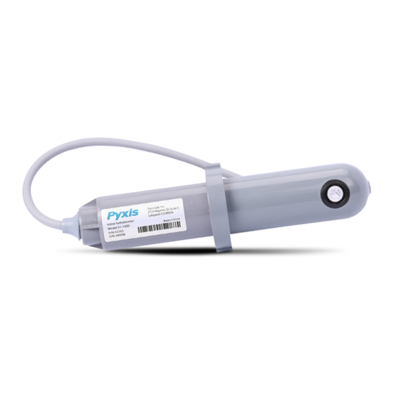
Pyxis ST-730 Series User Manual
Inline turbidity probes
Hide thumbs
Also See for ST-730 Series:
- User manual (20 pages) ,
- User manual (17 pages) ,
- Quick start manual (2 pages)
Summary of Contents for Pyxis ST-730 Series
- Page 1 ST-730 Series Inline Turbidity Probes User Manual February 23, 2020 Rev. 1.31 © 2017 Pyxis Lab, Inc. Pyxis Lab Proprietary and Confidential...
-
Page 2: Table Of Contents
8 Sensor Maintenance and Precaution 8.1 Methods to Cleaning ST-730 Series Probe ......8.2 Storage .......... - Page 3 Pyxis Lab, Inc. Standard Limited Warranty Pyxis Lab warrants its products for defects in materials and workmanship. Pyxis Lab will, at its option, repair or replace instrument components that prove to be defective with new or remanufactured components (i.e., equivalent to new).
-
Page 4: Introduction
1 Introduction The Pyxis ST-730 series is a variety of pre-scaled inline probes all measuring turbidity in water using a white LED as the excitation light source and by measuring the scattered light at a 90-degree angle with respect to the excitation beam. -
Page 5: Standard Accessories
3.1 Standard Accessories • Tee Assembly 3/4” NPT (1x Tee, O-ring, and Nut) P/N: ST-001 • 7-Pin Female Adapter/Flying Leads Cable (2 ft) P/N: MA-1100 • User Manual available online at www.chemtrol.com.au/probes-selection/inline-turbidity-meter-series 3.2 Optional Accessories Figure 1. ST-730 Series User Manual... -
Page 6: Installation
4 Installation The provided ST-001 Tee Assembly can be connected to a pipe system through the 3/4” female ports, either socket or NPT threaded. To properly install the ST-730 series probe into the ST-001 Tee Assembly, follow the steps below: 1. -
Page 7: Wiring
4.2 Connecting via Bluetooth A Bluetooth adapter (P/N: MA-WB) can be used to connect an ST-730 series probe to a smart phone with the uPyxis® Mobile app or a computer with the uPyxis® Desktop app. Figure 4. Bluetooth connection to ST-730 series probe 4.3 Connecting via USB... -
Page 8: Setup And Calibration With Upyxis® Mobile App
5.2 Connecting to uPyxis® Mobile App Turn on Bluetooth on your mobile phone (Do not pair the phone Bluetooth to the ST-730 series probe). Open uPyxis® Mobile App. Once the app is open the app will start to search for the sensor. When the uPyxis®... -
Page 9: Calibration Screen And Reading
When connected, the uPyxis® Mobile App will default to the Calibration screen. From the Calibration screen, you can perform calibrations by pressing on Zero Calibration, Slope Calibration, and 4-20mA Span. Follow the screen instructions for each calibration step. Figure 8. ST-730 Series User Manual... -
Page 10: Diagnosis Screen
From the Diagnosis screen, you can check the diagnosis condition as well as Export & Upload. Figure 9. 5.5 Device Info Screen From the Device Info screen. You can name the Device or Product. Figure 10. ST-730 Series User Manual... -
Page 11: Setup And Calibration With Upyxis® Desktop App
Click Install to start the installation process. Follow the screen instructions to complete the USB driver and uPyxis installation. 6.2 Connecting to uPyxis® Desktop App When the uPyxis® Desktop App opens, to find your device, click on Device, then Connect via USB-RS485. Figure 12. ST-730 Series User Manual... -
Page 12: Information Screen
To calibrate the device, click on Calibration. On the Calibration screen there are three calibration tabs, Zero Calibration, Slope Calibration, and 4-20mA Span. The screen also displays the reading of the device. The reading refresh rate is every 4 seconds. Figure 14. ST-730 Series User Manual... - Page 13 Span. Then follow the instructions provided to alter the 4-20mA output span of the sensor, then click Set 20mA Span. Each sensor format will have a maximum 20 mA range allowed. 4-20mA Span setup must be maintained within the limit of its respective sensor. ST-730 Series User Manual...
-
Page 14: Diagnosis Screen
Figure 18. 7 Communication using Modbus RTU The ST-730 series probe is configured as a Modbus slave d evice. In addition to the NTU value, many op- erational parameters, including warning and error messages, are available via a Modbus RTU connection. -
Page 15: Sensor Maintenance And Precaution
Figure 19. Inline Probe Cleaning Solution Kit To clean the ST-730 series probe, soak the lower half of the probe in 100 mL inline probe cleaning solution for 30 minutes. Rinse the ST-730 series probe with distilled water and then check for the flashing blue light inside the ST-730 series probe quartz tube. -
Page 16: Storage
9 Troubleshooting If the ST-730 series probe output signal is not stable and fluctuates significantly, make an additional ground connection – connect the clear (shield, earth ground) wire to a conductor that contacts the sample water electrically such as a brass pipe adjacent to the ST-730 series tee.


Need help?
Do you have a question about the ST-730 Series and is the answer not in the manual?
Questions and answers