Advertisement
Quick Links
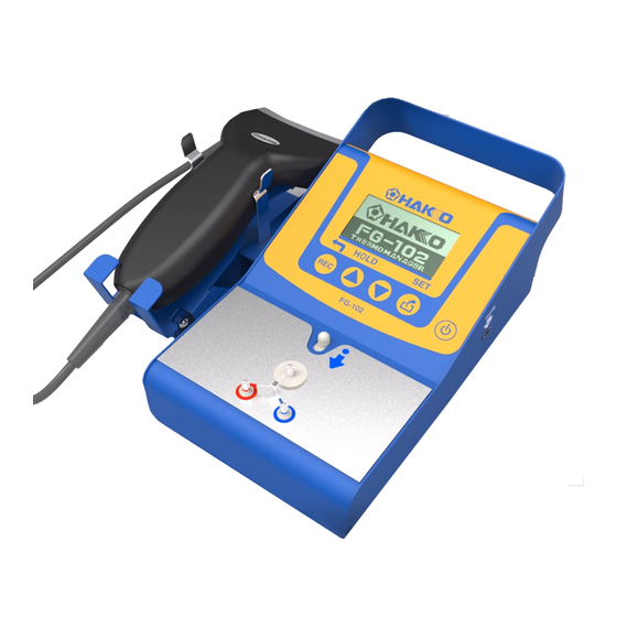
THERMOMETER
FG-102
Instruction manual
Thank you for purchasing the HAKKO FG-102 Thermometer.
This thermometer can transfer the following data to PC making them into one file.
And it can set up some particular temperature setting groups
to determine temperature ranges.
Please read this manual before operating the HAKKO FG-102.
Keep this manual readily accessible for reference.
Table of Contents
..................... 1
................................................. 2
................ 2
...................................................... 3
....................................................... 11
................................ 29
.......................................... 34
............................ 34
Advertisement

Summary of Contents for Hakko Electronics FG-102
-
Page 1: Table Of Contents
This thermometer can transfer the following data to PC making them into one file. And it can set up some particular temperature setting groups to determine temperature ranges. Please read this manual before operating the HAKKO FG-102. Keep this manual readily accessible for reference. Table of Contents 1. -
Page 2: Packing List And Part Names
1. PACKING LIST AND PART NAMES Please check to make sure that all items listed below are included in the package. HAKKO FG-102 ............ 1 AA sized (LR6) battery (6 pcs for trial) ....6 Barcode reader ............. 1 Barcode seal (For Unit ID 30 sheets) .... -
Page 3: Specifications
2. SPECIFICATIONS Celsius type Fahrenheit type Model name HAKKO FG-102 Resolution 1℃ 1℉ Temperature measurement range 0 - 700℃ 32 - 1,300℉ Applicable sensor K (CA) type thermocouple Measurement tolerance ±3°C (between 300 and 600°C) ±6°F (between 572 and 1,112°F) ±5°C (Other than above) -
Page 4: Initial Setup
4. INITIAL SETUP A. Preparation of the HAKKO FG-102 side ● Attach the sensor that comes with the equipment. 1. Press the slide button. The slide pin will move toward the terminal. 2. With the slide pin moved toward the terminal, attach the sensor. - Page 5 ● Connect barcode reader Connect barcode reader to the D-subminiature and fix the screws. Barcode reader connector Connecting barcode reader B. Preparation on the soldering iron side Stick the barcode that comes with the equipment or a printed one to the soldering iron station or the iron.
- Page 6 CPU:Intel Core i3-2370M 2.40Hz 4.0GB RAM ● Connection with PC ・Installing driver software To connect FG-102 with a PC, installation of the driver software is required. Please carry out installation from the accompanying CD. * Installation requires Administrator’s privileges. 1. Please insert the accompanying CD-ROM into the CD-ROM drive of the PC.
- Page 7 * If no window appears or the window was closed, double-click DriverInstaller located in the CD-ROM to start it. ・Connect the HAKKO FG-102 and the PC 1. Turning on the power of HAKKO FG-102 2. Connect it with the PC. Wait until FG-102 is recognized by the PC. This step may take several minutes.
- Page 8 3. Open the Device Manager and make sure that the driver has been installed. Checking Device Manager * The COM number may differ from the one shown in the picture below. The latest version of the driver software can be downloaded from Cypress’s web site. Cypress’s web site http://www.cypress.com/ User registration to Cypress.com is required for downloading.
- Page 9 * If the software on the PC will not run "The configuration of this application incorrect, it was not able to start the application. There are cases where the issue is resolved by installing the application again. ", "***. Dll can not be found." If the display such as leaves, the following software to the Microsoft home page Download from, please install.
- Page 10 4. Double click the software “FG102_DataSave.exe” and start it. Start screen of the software 5. Select File-Port Setting and open it. Select Port Setting Screen of Port Setting...
- Page 11 6. Input your written number for COM and press OK button. Input the port number...
-
Page 12: Operation
5. OPERATION Control buttons Power button This unit has the following four (4) buttons. The major functions are as shown below: recording data / going back to previous screen - scrolling displayed data; changing a value/MAXHOLD - scrolling displayed data; changing a value - ... - Page 13 ■ Power save/Auto shut-off To reduce the battery power consumption, the device may enter into the state of power save/auto shut-off after elapse a certain period of time. In the power save state, while the contents being edited in the Setting mode are retained, they will be lost once the device is shut down. ・In case of the measurement mode If there is no temperature input exceeding 100°C (212°F) for a period of 3 minutes or over, or no operation of button, the device will be powered OFF.
- Page 14 ● Operation menu Press the button to change the MODE. When the unit is not operated for 3 minutes, the auto shutoff function is activated. (Refer to Measurement P14) MODE (Refer toP15) Record MODE Unit record (Refer toP17) MODE Fail List (Refer toP18) MODE Calibration date (Refer toP18)
- Page 15 ・Wipe off any flux deposited on the terminal with alcohol. (Do not use thinner or benzine.) CAUTION Do not directly blow any hot air (HAKKO FR-810, etc.) to FG102 for the measurement. Otherwise, HAKKO FG-102 main body may be broken.
- Page 16 ■ MAXHOLD function Pressing the button causes “H” icon to appear on the lower right corner of the screen. In that state, the maximum temperature will be always displayed. ・When short-pressed (for less than 2 seconds) While, in the MAXHOLD state, the screen always shows the MAX temperature alone, once the button is pressed for a short time, the indicated value will be reset once and the new MAX temperature after the press of the button will be shown thereafter.
- Page 17 3. Measure the temperature. The following shows the temperature measurement procedure in the recording mode. U n i t ID 00001 1) Put the iron tip into contact with the sensor. When the temperature rises, the HOLD icon Meas ID 00001 starts blinking.
- Page 18 ■ Checking the saved data By pressing the button after recording the temperature or immediately after the transition to the recording mode, you can view the measurement data recorded previously. ・The data may be scrolled by pressing the button. ・Reading the unit ID causes the return to the recording operation. C.
- Page 19 D. Fail List MODE The screen displays the data that proved fail through the temperature range judgment. Scroll the data by using the button. * If there is no fail data, the relevant items will be shown blank. Fail List Inst 000001 Meas ID 000001...
- Page 20 F. M’ment number MODE Pressing the button again causes the transition to the M'ment number mode. In this mode, the screen displays the temperature measurement rounds conducted in the measurement mode and recording mode. In the measurement mode, the count will add up if the iron tip is kept in contact for a long time. It is recommended to use it as a guide for the replacement of the sensor.
- Page 21 H. Setting MODE This mode allows you to set a variety of settings of the thermometer. ・Password entry Upon transition to the setting mode, you will be prompted to enter the password. 1. Using the or button, select a number for each digit. 2.
- Page 22 ①Setting date (Date setting) You can set the clock in the order of year, month, day, hour and minute. The cursor will blink at the position being set. Set the number by using the button and press the button to determine the setting.
- Page 23 Selectable values are: 0 to 1300 for Temp and 1 to 250 for Max and Min. Min is a value in the negative direction from the temperature setting. Shown below is an example. Example)When setting a range of ±10°C with the iron temperature setting of 360°C: Temp : 360℃...
- Page 24 ④Next calibration date notification (Cal notification) When this function is set ON, you will be notified as shown on the figure below when you turn on the power 14 days prior to the next scheduled calibration date. N e e d c a l i b r a t i o n d u e t o e x p i r a t i o n Calibration date notification screen...
- Page 25 ⑤Group registration (Gp registration) You can set unit IDs in each group that is set in the range setting. Pressing the button on the new registration screen will bring you back to the setting screen. 1. Select a group No. at first and press the button to determine it.
- Page 26 ■ If the entered unit ID is already registered, the following message will be shown. Press the button to return to the “Setting” menu screen. U n i t I D : * * * * * * i s a l r e a d y r e g i s t e r e d .
- Page 27 ⑥Deleting from group(Gp deletion) With this function, you can delete unit IDs from each group. Set the number by using the button and press the button to determine the setting. * If there is no unit ID registered for the designated group, the buzzer will beep and nothing will be displayed.
- Page 28 ⑦Resetting cumulative rounds (Del cumulative) Reset the temperature measurement rounds to zero (0). Set the number by using the button and press the button to determine the setting. Select Yes to delete or No to cancel. D e l e t i n g M ’...
- Page 29 ⑨Setting password (Pass setting) Reset the password for entering the setting mode. 1. First of all, enter the previous password (Last pass). Set the number by using the button and press the button to determine the setting. Usable charactersinclude numbers 0 - 9 and letters A - Z. 2.
-
Page 30: Saving Data On The Pc
6. SAVING DATA ON THE PC Each data recording mode and Group ID List mode, it is possible to transfer to the PC. 1. Ensure that the device is connected with the PC using a USB cable. Connected to a PC 2. Double click the software “FG102_DataSave.exe” and start it. Record MODE Group ID List MODE... - Page 31 [↑] Indication of transfer in progress Indication of transfer in progress Select either Yes or No Transfer end (DATA clear or not.) (FG-102) W a n t t o d e l e t e ? Completed (Refer to P32 “Saving the data”) Data delete confirmation Press the button (FG-102)
- Page 32 ● Data received screen (Record MODE) Once the data have been successfully transferred, the Receive Data screen as shown below will be displayed. RecieveData screen ● Saving the data (Record MODE) ・ Select ‘File - Save Data’ on the RecieveData window. ・...
- Page 33 ● Data received screen (Group ID List MODE) Once the data have been successfully transferred, the Receive Data screen as shown below will be displayed. Group List Recieve screen ● Saving the data (Group ID List MODE) ・ Select ‘File - Save Group List’ on the RecieveData window. ・...
- Page 34 If, when the PC software has been started, any discrepancy of clock is detected between the HAKKO FG-102 main body and the PC, the clock synchronization screen will be shown. 1. To correct the discrepancy, click the OK button on the screen.
-
Page 35: Error Messages
S y s t e m hardware and displays. e r r o r System error display TROUBLESHOOTING GUIDE The HAKKO FG-102 does not operate even when the power switch is turned ON. :Is the battery attached in the battery box? CHECK ACTION :Set the batteries. - Page 36 Software does not start : "The configuration of this application incorrect, it was not able to start the application. ACTION There are cases where the issue is resolved by installing the application again. ", "***. Dll can not be found." If the display such as leaves, the following software to the Microsoft home page Download from, please install.
Need help?
Do you have a question about the FG-102 and is the answer not in the manual?
Questions and answers