Advertisement
Advertisement
Table of Contents

Related Manuals for Mareli Systems PB 40


Summary of Contents for Mareli Systems PB 40
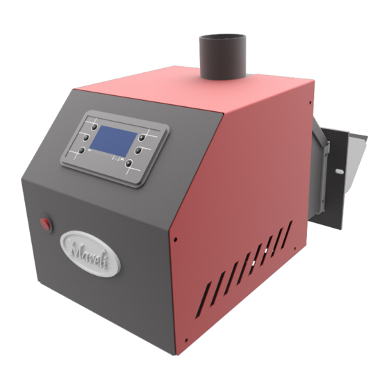
- Page 1 Mareli Systems PB 40 Pellet burner Assembly and exploitation manual...
- Page 2 “Mareli Systems” expresses its gratitude towards the clients who purchased the manufactured products. • “Mareli Systems” provides the present manual as an aid to the team, which will install, adjust and main- tain the device, as well as to the client which will exploit it.
- Page 3 Mareli Systems The pellet burner is a compact modular design with integrated elec- tronic control unit, consisting of the following components: Combustion chamber made of high quality stainless steel; Grill in the combustion chamber that is easily removed and al- lows for easy ash removal;...
- Page 4 Mareli Systems 3. Connection (installation) to the boiler: The pellet burner can be attached to a steel or cast-iron boiler with pow- er from 6 to 40KW. The minimum depth of the combustion chamber should be 450 mm. Pellet burner without secondary air supply.
- Page 5 4. Maintenance and operation of the pellet burner Requirements for the characteristics of the fuel, which is used for operation of a pellet burner PB 40 KW The following table shows the requirements for the types of wood pellets utilized in automated pellet burner.
-
Page 6: Pellet Burner Cleaning
Mareli Systems The joint operation of the system which the automated pellet burner applies to / depends on: • Heat output to which the burner is set; • The heating surfaces of the heater, for which it is intended. •... -
Page 7: Possible Faults And Troubleshooting
POSSIBLE FAULTS AND TROUBLESHOOTING: The verification shall be carried out only by a qualified electrical technician or an authorized by Mareli Systems service centre. The unit does not work: •... -
Page 8: Additional Information
Mareli Systems It is important that faulty parts to be replaced immediately !!! Always keep in stock additional photo sensor and heater for replacement. At the end of the period, upon decommissioning the burner, clean the fuel surfaces from any deposits. Clean the screw conveyor and the hopper from residual sawdust. - Page 9 Mareli Systems If the facility does not operate satisfactorily: • Check the quality of pellets (must be free from dust). Upon normal operation of the burner, the quantity of the pellets on the grate (combustion basin) must be such so that its holes are covered.
- Page 10 Mareli Systems Faults and Troubleshooting In the presence of a fault in the operation of the burner-boiler system, one should be familiar with the prob- lems and how to solve them as described in the user manual for operation of steel hot water boiler, as well as in such for automated pellet burner.
- Page 11 Mareli Systems CONTROL PANEL: USE AND FUNCTIONS The main frame shows: time and date, chrono activation, combustion power and recipe, functioning state, error code, main temperature, main thermostat, summer/winter mode. Button Function Exit Menu/Submenu; Ignition and extinguishing (push for 3 seconds), Reset errors (push for 3 seconds), Enable/disable chrono;...
- Page 12 Mareli Systems MESSAGES Description Code Sond Anomaly of the probes checking, during Check Up phase. Room temperature greater than 99 °C. Clean This message noti es that the planned hours of functioning are reached. Port Door Open. Ignition The message appears if the system is turned o during Ignition (after Preload) not manually: the system will stop only when it goes in Run Mode.
- Page 13 Mareli Systems CHRONO This Manu allows selecting the programming modalities and and the Ignition/Extinguishing time slots. Modality - It allows selecting the disired modality, or disable all set programming. Disable 1. Enter modi cation mode through the key P3. Daily 2.
-
Page 14: Wiring Diagram
Mareli Systems WIRING DIAGRAM... - Page 15 Mareli Systems...
- Page 16 MARELI SYSTEMS disclaims any responsibility for possible inaccuracies contained in this manu- al if they are due to printing or transcription errors. We reserve the right to make any change that appears to be necessary or useful without harm the essential characteristics.
Need help?
Do you have a question about the PB 40 and is the answer not in the manual?
Questions and answers