Advertisement
Quick Links
Advertisement

Related Manuals for Expert Sleepers Select Bus breakout

Summary of Contents for Expert Sleepers Select Bus breakout
- Page 1 Select Bus breakout Assembly instructions...
- Page 2 1. Check your parts Part Number Quantity Part L78L05ACZ (5V regulator) H11L1M (optocoupler) Q1-2 2N7000 (MOSFET transistor) BZX79-C3V3 (3.3V zener diode) R1-3 220R resistor 470R resistor R5-7 10K resistor 1M resistor 2 pin header 16 pin boxed header JK1-2 5-pin DIN socket Front panel Power cable (16 way IDC) Jumper link...
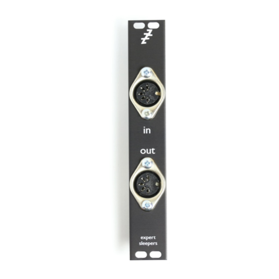
- Page 3 2. Attach the DIN sockets to front panel Use the M3 nuts and machine screws to attach the sockets to the panel. Do this now! You won’t be able to do it after soldering the sockets to the PCB. Make sure the sockets are rotated correctly, or they won’t match up with the PCB.
- Page 4 3. Insert and solder D1 Make sure the black band on the diode matches the stripe on the PCB. 4. Insert and solder R1-3 Insert the three 220R resistors (colour code red-red-black-black).
- Page 5 5. Insert and solder R4 Insert the 470R resistor (colour code yellow-purple-black-black). 6. Insert and solder R5-6 Insert two of the 10K resistors (colour code brown-black-black-red).
- Page 6 7. Insert and solder R8 Insert the 1M resistor (colour code brown-black-black-yellow). 8. Insert and solder IC2 Insert the optocoupler.
- Page 7 9. Insert and solder R7 Insert the remaining 10K resistor (colour code brown-black-black-red). 10. Insert and solder IC1 Insert the voltage regulator. Note the flat surface of the case aligns with the shape on the PCB.
- Page 8 11. Insert and solder Q1-2 Insert the transistors. Note the flat surfaces of the cases align with the shapes on the PCB. 12. Insert and solder JP1. Insert the 2 pin header.
- Page 9 13. Fit the jumper link Attach the jumper to JP1, if the module is to drive the Select Bus. 14. Insert and solder SV1 Insert the 16 way header. Note the orientation of the keying hole.
- Page 10 15. Solder the DIN sockets to the PCB Solder the two DIN sockets to the PCB.
-
Page 11: You're Done
16. You’re done!
Need help?
Do you have a question about the Select Bus breakout and is the answer not in the manual?
Questions and answers