Advertisement
Advertisement
Table of Contents

Subscribe to Our Youtube Channel
Summary of Contents for Show Tec Shogun 3D+RGB
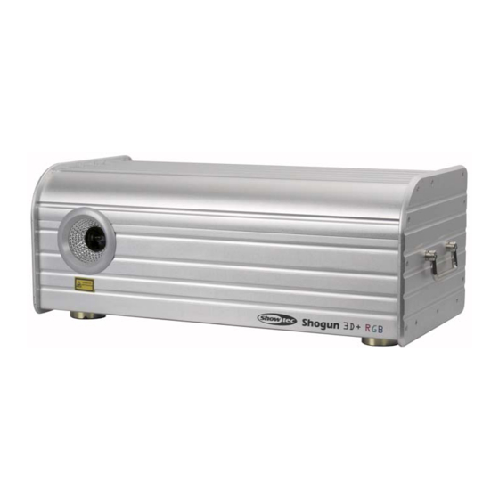
- Page 1 Shogun 3D+RGB ORDERCODE 30974...
- Page 2 ATTENTION 1. Must operate according to the user manual. Don't separate the light personally. Call the technician when the machine breaks down. 2. Please do not see the laser beam directly to avoid any damage. 3. Before connect or disconnect the power, please adjust the luminance of the laser diode to the least to avoid any damage to the laser diode.
-
Page 3: Open The Box For Checking
OPEN THE BOX FOR CHECKING In order to use this product safety and reasonable for the users, please read over this manual carefully before use and the operation must strictly according to this manual to avoid any damage to the product and personal safety. Once after received this products please take and put carefully. -
Page 4: Control Board Instruction
CONTROL BOARD INSTRUCTION RGB LASER Po we r 1 2 0W Cla ss 1 Re d L as e r Class 3 B 6 35 n m >1 5 0m W G re e n L a s er Class 3 B 5 3 2n m >6 0 mW Blu e L a s er Class 3 B 4 7 3n m... - Page 5 music mode/auto mode/slave mode setting: FUNCTION This bit disable DMX mode and MUSIC MODE enable music/auto slave mode AUTO MODE SLAVE MODE DMX address code setting: “ ” “ ” “ ” “ ” in the binary, each digit have 0 or 1 just correspond to OFF or...
-
Page 6: Specification
No move 0-63 Horizontal move Horizontal & 64~127 vertical move 128~191 Vertical move Horizontal & vertical move 192~255 0~63 stretch 64~127 Horizontal stretch Horizontal & 128~191 vertical stretch ertical stretch 192~255 Horizontal & vertical stretch Zoom 0~85 Small To Large & Zoom from one point to large 86~169 Large To Small... - Page 7 1 2 3 4 5 6 7 8 9 1 2 3 4 5 6 7 8 S2 & S3 TTL-SWITCH BOARD Description for TTL-switch board: This board have three input source, they are Internal Programboard (X1,Y1,R1,G1,B1) and ILDA DB25F (X2,Y2,R2,G2,B2) and USB graphics interface card (X3,Y3,R3,G3,B3).
- Page 8 Appendix: ILDA DB 25F PINOUTS DB 25 definens + + -5 to + + -5 to + Intensity/Blanking + 0V to 2.5V Interlock A Connected to pin 17 inside the Qm2000 + + 0V to 2.5V + Green + 0V to 2.5V +...
- Page 9 2005 Showtec.
Need help?
Do you have a question about the Shogun 3D+RGB and is the answer not in the manual?
Questions and answers