
Related Manuals for Domburg ASB

Summary of Contents for Domburg ASB
- Page 1 Domburg Train Support Your partner in Model Railway Technology DTS Manual: Analogue Servo Control ASB Version 2 - 2019...
-
Page 2: Table Of Contents
Manual ASB │ version 2 – 2019 Content Introduction ................................. 3 How the ASB works ............................. 4 The functionality of the ASB ..........................4 Possibility’s to control the ASB ........................4 Mounting ................................5 Servo bracket ..............................5 Servo ................................5 Spring steel wire .............................. -
Page 3: Introduction
But for the normal model railroader there was no solution yet, until now!!! I wish you much ease of use with the ASB, if you have suggestions for improving the product or a critical note. Let me know by sending an email to info@domburgtrainsupport.nl... -
Page 4: How The Asb Works
The functionality of the ASB The ASB works based on a PIC interface with a code with which it can function. For the PCB to work properly, the power supply offered is reduced to 5VDC, which allows the PIC to operate the servos and the relay. -
Page 5: Mounting
Manual ASB │ version 2 – 2019 Mounting The ASB has 4 mounting points. It is advisable to mount the printed circuit board at height due to the heat development of the voltage regulator. Preferably with the components on top. -
Page 6: Spring Steel Wire
Manual ASB │ version 2 – 2019 Spring steel wire The spring steel wire can be used to affect the transfer between the servo arm and the object to be moved. You do this as directly as possible. Every kind of bending, Z-cut and V-cut are not necessary and counteract the movements. -
Page 7: Aansluiten
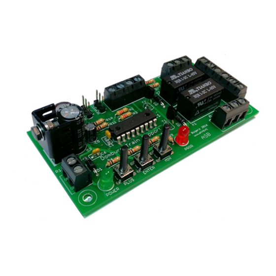
Manual ASB │ version 2 – 2019 Aansluiten Figure 1 Positive voltage between 7-35 VDC Well-known minus, or the Ground Servo 1 First servo connection Servo 2 Connection second servo Rocker switch associated with servo 1 Rocker switch associated with servo 2... -
Page 8: Power
Manual ASB │ version 2 – 2019 Power The supply voltage that must be offered on the ASB is a direct voltage of a minimum of 7 volts and a maximum of 35 volts. A voltage between 12 and 15 volts is recommended. Offering an alternating voltage is not allowed, if you do this can cause irreparable damage to the printed circuit board and its components. -
Page 9: Relay
Manual ASB │ version 2 – 2019 Relay Each servo has a relay that switches to the middle position of the servo. As shown in figure 1, each relay has two changeover contacts. This means that every contact consists of a Common (COM), Normally Closed (NC) and Normally Open (NO). -
Page 10: Configuring The Controller
After step 8, both servos go into the middle position and the ASB is ready for use. If desired, you can repeat the steps, the fact is that the order is fixed. You can also walk through the steps without making a change. -
Page 11: Fault Status
Fault status The centre of the servo is very important for the ASB because the left and right results are measured with the middle position. If this position is not programmed between the two results, the servo will get into a "loop"...
Need help?
Do you have a question about the ASB and is the answer not in the manual?
Questions and answers