Advertisement
Quick Links
Advertisement

Summary of Contents for KOHJINSHA KP-1
- Page 1 Instruction Manual DIGITAL POWER METER KP-1 Rev1.1 18. July. 2017...
- Page 2 Rear Panel・・・・・・・・・・・・・・・4 Please read this manual carefully before you start Preparation before using・・・・・・・・・5 using KP-1. We would like you to use KP-1 as long as possible. ■Operation FWD Power measurement・・・・・・・・・5 REF Power measurement・・・・・・・・・5 ■Features...
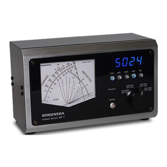
- Page 3 Digital display shows FWD power when this 9. POWER Switch button is pressed. This switch is used to turn on the KP-1. The button shines red when the power supply is 4. REF Button Digital display shows REF power when this button is pressed.
- Page 4 12 and 13 are normally connected inside of KP-1. When the SWR accidentally gets higher than the threshold value, KP-1 automatically cuts off the line to protect your amplifier and/or antenna. (Go to page 6 for how to set up)
- Page 5 For this reason you need to use PEP meter to read the power. KP-1 has a circuit that read ●Connect IN connector to your TRX with 50ohm peak value of the power when you press 6 PEP coax cable with SO239 on both sides.
- Page 6 Here is an example of your setting up P3. display as [P3-88]. Then you can choose P3 parameters with FWD and REF buttons. Let the KP-1 setup mode as described first part of FWD button makes brighter. REF button this page.
- Page 7 ● P6 Mode (Factory Setup) If you want to reset to factory setup, choose 0 with FWD or REF button, and then press DEL. If you press DEL when 1 was shown, the operation is canceled. Factory setup values SWR protection: Lock mode SWR protection threshold value FWD and REF offset value A/D calibrate mode voltage display...
- Page 8 ■ Specification Frequency Range 1.8MHz to 30MHz Measuring Power Range 10W to 10KW Power Range Selection FWD 500W/1KW/5KW/10KW REF 125W/250W/1250W/2500W Accuracy +-7% at full scale of each range Minimum power required to measure SWR approximate 8W Insertion Loss Less than 0.1dB Input/Output Impedance 50ohm Input/Output Connectors...
- Page 9 - 9 -...
Need help?
Do you have a question about the KP-1 and is the answer not in the manual?
Questions and answers