Table of Contents
Advertisement
Available languages
Available languages
Quick Links
Advertisement
Table of Contents

Summary of Contents for Helmut BSC350
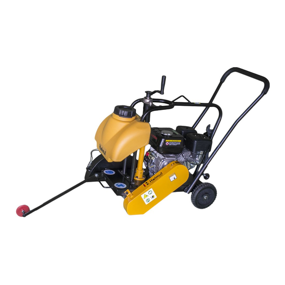
- Page 1 BSC350/BSC350H CONCRETE CUTTER EN|RU 01/2014 www.helmutworld.com/support...
- Page 2 All possible situations cannot be covered in these instructions. Care must be exercised by everyone using, Maintaining or working near this equipment. «Helmut» в России Телефон : 8 (495) 518-94-22 ...
-
Page 3: General Safety
1 RULES FOR SAFE OPERATION WARNING: Failure to follow instructions in this manual may lead to serious injury or even death! This equipment is to be operated by trained and qualified personnel only! This equipment is for industrial use only. The following safety guidelines should always be used when operating these Concrete Cutters: GENERAL SAFETY... -
Page 4: Diamond Blade Safety
■ ALWAYS read, understand, and follow procedures in operator’s Manual before attempting to operate equipment. ■ ALWAYS be sure to operator is familiar with proper safety precautions and operating techniques before using the cutter. ■ Stop the engine when leaving the cutter unattended. ■... -
Page 5: Cutter Transportation Safety
■ The engine governor is designed to permit maximum engine speed in a no-load condition. Speeds that exceed this limit may cause the diamond blade to exceed the maximum safe allowable speed. CUTTER TRANSPORTATION SAFETY ■ Use the lifting bail and appropriate lifting equipment to ensure the safe movement of the cutter. -
Page 6: Operation
OPERATION Introduction/Determining the Right Machine Congratulations on your pumhase of our Cutter! You’ve made an excellent choice! Our floor cutter has been specifically designed as the ideal machine for the professional contractor who is engaged in concrete and asphalt flat sawing. The machines used for the primary purpose of 'flat”... -
Page 7: Installing Blade
INSTALLING BLADE Be certain that the spark plug is disconnected or saw is unplugged. Remove the blade shaft nut, and take off outside blade shaft flange. Clean off any foreign particles on the clamping surfaces of flanges and on the mounting surface of the blade. -
Page 8: To Start Cutting
Hot Start-open the valve under the gas tank all the way if it has been shut off. Open the throttle approximately half way. Do not apply the choke. Pull the starter rope sharply until the engine starts. When the engine starts, adjust the throttle. Always operate the engine at full throttle when under load. -
Page 9: Belts&Pulleys
BELTS&PULLEYS NEVER MAKE ADJUSTMENTS TO V-BELTS AND PULLEYS WHILE ENGINE IS RUNNING The best tension for a v-belt drive is the lowest tension at which the belts will not slip under full load. Take up tension until the belts are snug in the grooves. Run the drive for about five (5) minutes to “seat"... -
Page 10: Dry Cutting
Misalignment will show up as a gap between the pulley face and straight edge. Make sure there is clearance between arbor pulley and saw base on both sides. DRY CUTTING • Never operate any saw without safety guards in place. •... - Page 11 • Clean machine before starting lubrication maintenance. • Insure machine is on solid, level ground before starting maintenance. • During lubrication maintenance insures strict cleanliness is observed at all times. • To avoid the risk of accidents, use the correct tool for the job and keep tools clean.
-
Page 12: Major Components
Major Components... - Page 13 Major Components ITEM NO. PART NO. DESCRIPTION 2010101 BOLT M8*25 2010102 WASHER 8 2010103 INJECTION MOUTH 2010104 SEAL RING 2010201 ELBOW 2010202 COCK 2010203 PLASTIC PIPE 2010204 2010301 BOLT M10x25 2010302 WASHER 10 2010303 BLADE GUARD 2010304 NUT(BUTTERFLY)M10 2010305 NUTM8 2010306 PROTECTIVE MAT 2010401...
-
Page 14: Transmission Assy
Transmission Assy... - Page 15 Transmission Assy ITEM NO. PART NO. DESCRIPTION BOLT M8*25 2020101 WASHER 8 2020102 2020103 WHEEL HANDLE 2020104 BOLT M 10x30 2020105 WASHER10 BEARING ASSY. 2020106 2020107 KEY 6x30 2020108 MAIN SHAFT 2020109 STEM 2020110 SPRING WASHER M10 NUT M10 2020111 PEDAL 2020201 2020202...
- Page 16 Depth Adjusting Assy...
- Page 17 Depth Adjusting Assy ITEM NO. PART NO. DESCRIPTION 2030101 PULLING NUT 2030102 SPRING PIN 4 x 16 2030103 SPRING 2030104 2030201 WHEEL HANDLE 2030202 BOLT МЮхЗО 2030203 WASHER10 2030204 BOLT M8*25 2030205 WASHER8 2030206 BOLT M8*12 2030207 BEARING ASSY. 2030208 POSITION PLATE 2030209 SCREW STEM...
-
Page 18: Engine Assy
Engine Assy... - Page 19 ITEM NO. PART NO. DESCRIPTION 2040101 FIXING PLATE 2040102 CONNECTOR 2040103 CABLE 2040104 CABLE PIPE 2040105 SCREW M16*25 2040106 WASHER M6 2040107 THROTTLE CONTROL 2040201-1 DIESEL,KAMA 186 2040201-2 PETROL, 188F 2040201-3 PETROL,EH36D 2040201-4 PETROL,HONDA GX390K1 1 2040202-1 KEY FOR DIESEL ENGINE 1 2040202-2 KEY FOR PETROL ENGINE 1 PULLEY FOR DIESEL...
-
Page 20: Electric Starter Assy
Electric Starter Assy... - Page 21 Electric Starter Assy ITEM NO. PART NO. DESCRIPTION 2050101 2050102 TIGHTENING SPACER 2050103 WASHER 2050104 ELECTRIC CONNECTOR 2050201 BOLT M8x20 2050202 ELECTRIC CABLE 2050203 NUT M6 2050204 PLUG NEGAIVE 2050301 WIRE 2050302 PLUG POSITIVE 2050401 BATTERY 2050402 BATTERY GUARD 2050403 WASHER M8 2050501 WIRE...
- Page 22 Описание и работа Нарезчики швов используется для нарезания швов в твердых покрытиях при проведении дорожно-строительных и ремонтных работах. Они могут применяться для работ по устройству траншей под коммуникации, при разделке трещин. Высокие показатели производительности обеспечивают современные конструкции швонарезчиков, а также высокое качество режущего алмазного круга специально произведенного...
- Page 23 Конструкция Швонарезчик состоит из следующих составных частей: привод - двигатель с клиноременной передачей на вал фрезы; рама - сварная конструкция со смонтированными на ней корпусом фрезы, опорными колесами; ручка - разъемная конструкция из труб с устройством подъема и опускания фрезы; ограждение...
- Page 24 Управление и обслуживание Машина поставляется без топлива. Изготовитель мотора рекомендует использовать в качестве топлива автомобильный бензин А92. Мотор крепится к раме 4-мя винтами М10. На вал машины можно установить алмазный режущий диск с внутренним диаметром отверстия 25,4 мм. Устанавливать алмазный режущий диск необходимо, учитывая...
- Page 25 этому становится возможным одновременно при погружении направляющего диска в уже прорезанный шов выполнить следующий параллельный рез. Система охлаждения. Охлаждающая жидкость подается на режущий диск из резервуара вместимостью 20 л. На линии подачи установлен запорный кран, благодаря которому устанавливается необходимый поток. Резервуар оснащен вентиляционным отверстием, которое...
- Page 26 Ввод в эксплуатацию При вводе в эксплуатацию машины выполнить следующие действия: Ознакомиться с инструкцией по эксплуатации машины и мотора. 2. Проверить количество масла в моторе (минеральное SAE 15W40). Залить топливо (бензин А92 без содержания свинца). Надеть алмазный режущий диск и надежно закрепить (не забывать о соответствующем...
- Page 27 Подготовка к эксплуатации Снять консервационную смазку. Проверить смазку подшипниковых узлов (при необходимости смазать). Проверить затяжку всех резьбовых соединений. Проверить натяжение ременной передачи. Номинальный прогиб ремня должен быть в пределах 8-10 мм при усилии 98Н (10кгс). Проверить смещение...
Need help?
Do you have a question about the BSC350 and is the answer not in the manual?
Questions and answers