
Summary of Contents for DIC 711
- Page 1 www.diclaadsystemen.nl OPLADEN KAN OOK MOOI ZIJN ALUMINIUM INBOUW OPLAADPUNT MONTAGE EN GEBRUIK HANDLEIDING Plug and Charge 3,7kW 230V / 11kW 400V NL | DE | EN |...
- Page 2 www.diclaadsystemen.nl INHOUDSOPGAVE Inbouw oplaadpunt plug and charge. Veiligheidsvoorschriften Montage plan 2.1 Aansluitschema In bedrijf stellen 3.1 Voeding inschakelen 3.2 Testen Laadpunt activeren...
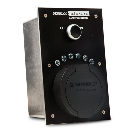
- Page 3 www.diclaadsystemen.nl Ook in zwart leverbaar.
- Page 4 www.diclaadsystemen.nl VEILIGHEIDSVOORSCHRIFTEN Lees eerst goed de bijgeleverde documentatie. Houd er goed rekening mee dat u aan een elektrische installatie werkt! Zorg tijdens de montage van het inbouw oplaadpunt dat er géén spanning aanwezig is. Het laadstation is volgens de laatste geldende voorschriften ontworpen, volgens de richtlijnen IEC 61851.
- Page 5 www.diclaadsystemen.nl Foto 2 - boor de gaten Foto 1 - uitsparing zagen Foto 3 - bevestig de rubberen afdichting 2.1 Aansluitschema Laadpuntzijde Kabelzijde Omschrijving Paars Paars Paars Roze Geel Geel Blauw1 Rood Motor Blauw2 Motor Blauw3 Blauw Motor Zwart Puls drukknop Grijs Puls drukknop Groen...
- Page 6 www.diclaadsystemen.nl Stuurstroom kabel CY 12 x 0,75mm maximale lengte 4 meter. Voedingskabel 5 x 2,5mm Ymvk of een grondkabel 4x2,5mm2 Ymvkas. Ook bij een 3,7kW model bij voorkeur een kabel aanleggen met een 3 Fase nul en aarde. Monteer de controle box (foto 4). Foto 4 - montage controle box IN BEDRIJF STELLEN De voedingskabel van het inbouw laadpunt aansluiten achter een aparte automaat en...
- Page 7 www.diclaadsystemen.nl 3.1 Voeding inschakelen Schakel de voeding pas in wanneer alle bedrading is aangesloten. 3.2 Testen Plug de testkabel in het laadpunt met een verbruiker erin. LAADPUNT ACTIVEREN Activeer het laadpunt met de drukknop of sleutel schakelaar. Groen: Laadpunt laad en de stekker is vergrendeld. Verkoop via: inter BÄR GmbH + Co.
- Page 8 www.diclaadsystemen.nl AUFLADEN KANN AUCH SCHÖN SEIN ALUMINIUM EINBAU- LADESTATION MONTAGE- UND GEBRAUCHSANWEISUNG Plug and Charge 3,7 kW 230 V / 11 kW 400 V NL | DE | EN |...
-
Page 9: Table Of Contents
www.diclaadsystemen.nl INHALTSVERZEICHNIS Einbau-Ladestation Plug and Charge. Sicherheitshinweise Montage Plan 2.1 Anschlussplan Inbetriebnahme 3.1 Einschalten der Stromversorgung 3.2 Prüfung Aktivieren der EinbauLadestation... - Page 10 www.diclaadsystemen.nl Auch in schwarz lieferbar.
-
Page 11: Montageplan
www.diclaadsystemen.nl SICHERHEITSHINWEISE Bitte lesen Sie zuerst die Bedienungsanleitung sorgfältig durch. Achten Sie darauf, dass bei der Installation der Ladestation keine Spannung anliegt. Die Ladestation wurde nach den neuesten gültigen Vorschriften, gemäß IEC 61851, ausgelegt. Die sichere Montage darf nur von einem qualifizierten Elektriker eines zugelassenen Unternehmens durchgeführt werden. - Page 12 www.diclaadsystemen.nl Foto 2 - Bohren Sie die Löcher Foto 1 - Aussparüng sägen Foto 3 - Befestigung der Gummidichtung Ladepunkt-Seite Kabel-Seite Beschreibung Lila Lila Lila Rosa Gelb Gelb Blau1 Verriegelung Blau2 Weiß Verrigelung Blau3 Blau Verriegelung Weiß Schwarz Impulstaster Weiß Grau Impulstaster Grün...
-
Page 13: Anschlussplan
www.diclaadsystemen.nl 2.1 Anschlussplan Steuerstromkabel CY 12 x 0,75 mm² maximale Länge 4 Meter. Netzkabel 5 x 2,5 mm² YMVK oder ein Erdungskabel 4 x 2,5 mm² YMVKAS. Auch für ein 3,7 kW Modell ist es vorzuziehen, ein Kabel mit einem 3PhasenNeutralleiter und Erde zu installieren. -
Page 14: Einschalten Der Stromversorgung
www.diclaadsystemen.nl 3.1 Einschalten der Stromversorgung Schalten Sie die Stromversorgung erst dann ein, wenn alle Kabel angeschlossen sind. 3.2 Prüfung Stecken Sie die Messleitung mit einem Verbraucher in die Ladestation. AKTIVIEREN DER LADESTATION Aktivieren Sie die Ladestation mit dem Druckknopf oder Schlüsselschalter. Grün: Die Ladestation lädt und der Stecker ist verriegelt. - Page 15 www.diclaadsystemen.nl CHARGING CAN ALSO BE BEAUTIFUL ALUMINIUM BUILT-IN CHARGING STATION MOUNTING AND OPERATING INSTRUCTIONS Plug and Charge 3,7 kW 230 V / 11 kW 400 V NL | DE | EN |...
- Page 16 www.diclaadsystemen.nl TABLE OF CONTENTS Built-In Charging Station. Safety instructions Mounting Plan 2.1 Wiring diagram Implementing BuiltIn Charging Station 3.1 Switching on the power supply 3.2 Testing Activating BuiltIn Charging Station...
- Page 17 www.diclaadsystemen.nl Also available in black.
-
Page 18: Safety Instructions
www.diclaadsystemen.nl SAFETY INSTRUCTIONS Please read this operating instructions carefully first. Make sure that no voltage is present during the installation of the charging station. The charging station has been designed in accordance with the most recent regulations in force, in accordance with IEC 61851. Safe assembly may only be carried out by a qualified electrician from an approved company. -
Page 19: Wiring Diagram
www.diclaadsystemen.nl Photo 2 - Drill the holes Photo 1 - Sawing a cutout Photo 3 - Attaches the rubber seal 2.1 Wiring diagram Charging point side Cable side Description Purple Purple Purple Pink Yellow Yellow Blue1 Locking mechanism Blue2 White Locking mechanism Blue3 Blue... - Page 20 www.diclaadsystemen.nl Control current cable CY 12 x 0.75 mm² maximum length 4 meters. Power cable 5 x 2.5 mm² YMVK or a ground cable 4 x 2.5 mm² YMVKAS. Also for a 3.7 kW model it is preferable to install a cable with a 3 Phase neutral and earth. Mounting the control box.
-
Page 21: Switching On The Power Supply
www.diclaadsystemen.nl Terminal Wire colour Description black Pulse push button grey Pulse push button green LED + blue/red LED Control current protection 2 A glass fuse. 3.1 Switching on the power supply Do not turn on the power supply until all wiring is connected. 3.2 Testing Plug the test lead into the charging station with a consumer in it. - Page 22 Scholtensoven 6J, 7621HA Borne | Tel 074 - 266 04 28 info@diclaadsystemen.nl | www.diclaadsystemen.nl...
Need help?
Do you have a question about the 711 and is the answer not in the manual?
Questions and answers