Table of Contents
Advertisement
Quick Links
Advertisement
Table of Contents

Summary of Contents for Anite NEMO FSR1
- Page 1 SCANNER GUIDE Version 6.20...
- Page 2 The information in this manual is intended for informational use only and is subject to change without notice. Anite Finland Ltd assumes no responsibility or liability for any errors or inaccuracies that may appear in this user manual.
-
Page 3: Table Of Contents
NEMO FSR1 CONNECTING NEMO FSR1 SCANNER Changing the Nemo FSR1 IP Address Connecting a GPS Antenna to Nemo FSR1 CONNECTING NEMO FSR1 SCANNER TO NEMO INVEX CHASSIS STARTING NEMO FSR1 SCANNER NEMO FSR1 FIRMWARE UPDATE MEASURING WITH NEMO FSR1 SCANNER... - Page 4 Connecting R&S TSMW to Nemo Invex with a Network Switch STARTING ROHDE & SCHWARZ SCANNERS MEASURING WITH ROHDE & SCHWARZ SCANNERS Frequency Scanning TOP-N Pilot Scanning - UMTS TOP-N Pilot Scanning - CDMA/EVDO TOP-N Pilot Scanning - LTE Spectrum Scanning TROUBLESHOOTING SCANNERS NEMO FSR1...
-
Page 5: Nemo Fsr1
NEMO FSR1 CONNECTING NEMO FSR1 SCANNER Nemo FSR1 scanner is powered by 10 to 16 VDC. AC operation for the standalone receiver is achieved by using the optional AC power supply. The AC power supply is designed to work with 100 - 240VAC 50/60Hz. - Page 6 Nem o F S R1 2. Connect Ethernet cable(s) to the scanner Ethernet port(s) and to the Nemo Outdoor laptop. 3. Go to Control Panel | Network and Internet | Network and Sharing Center. Click on Change adapter settings. 4. Right-click on Local Area Connection and select Properties. In the Local Area Connection Properties dialog, select Internet Protocol Version 4 (TCP/IPv4) and click Properties.
- Page 7 Click OK and Close. ♦ Please note that by default the Nemo FSR1 is delivered with a fixed IP address. The IP address can be changed with a separate utility software. The following IP addresses are used in Nemo Outdoor: •...
-
Page 8: Changing The Nemo Fsr1 Ip Address
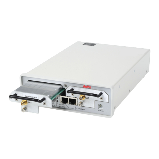
Power connector 7. The default address and name settings of the scanner are generally suitable for most users. There is no need to configure these settings when using the Nemo FSR1 scanner with Nemo Outdoor. 8. The status LEDs at the front panel display how the scanner is functioning. - Page 9 Nem o F S R1 Connect a PC to the Nemo FSR1 serial port using the serial adapter cable (available from Anite). The scanner serial port is located in the lower-right corner of the front panel. Switch on the scanner.
- Page 10 Nem o F S R1 In the COM1 Properties dialog, define the following settings: Bits per second: 115200 Data bits: 8 Parity: None Stop bits: 1 Flow control: Xon/Xoff Click OK and OK. An empty HyperTerminal window is opened.
- Page 11 Nem o F S R1 Press Enter on your keyboard. The following information is displayed. To change the IP address, press 2 and Enter. Enter the new IP address in format xxx.xxx.xxx.xxx. For example, 192.168.003.252. Press Enter.
- Page 12 Nem o F S R1 The IP address is changed and the window displays the new flash data with the new IP address. To update the scanner firmware and finalize the changes, press 0 and Enter. Confirm the firmware update by pressing Y and Enter. ♦...
-
Page 13: Connecting A Gps Antenna To Nemo Fsr1
30 minutes in GPS coverage before the antenna is disconnected and then every hour or two of walk testing have an additional 20 minutes in GPS coverage. The following GPS antenna is delivered with the Nemo FSR1: • Mighty Mouse III •... -
Page 14: Connecting Nemo Fsr1 Scanner To Nemo Invex Chassis
INVEX CHASSIS Nemo FSR1 is connected to the Nemo Invex chassis (SI module) with an Ethernet cable. Ethernet ports are located on the front panel of the Nemo FSR1 scanner and on the front panel of the Nemo Invex SI module. - Page 15 Nemo FSR1 power cable can be connected to the Nemo Invex chassis. The scanner power connector is located at the rear of the chassis. The Nemo FSR1 scanner can be attached on top of the Nemo Invex chassis with a mounting plate.
-
Page 16: Starting Nemo Fsr1 Scanner
Nem o F S R1 Clearance for air ventilation around the Nemo FSR1 is as follows: • Back 10 cm • Left side 3 cm • Right side 3 cm (not applicable for Rev B scanner) ♦ Note that the air intake is on the left side and exhaust on the back. -
Page 17: Nemo Fsr1 Firmware Update
NEMO FSR1 FIRMWARE UPDATE Nemo FSR1 firmware can be updated using the Nemo FSR1 Firmware Update Utility or through Nemo Outdoor. For detailed information on using the update utility, please refer to the Nemo FSR1 Firmware Update Utility Instructions document. -
Page 18: Measuring With Nemo Fsr1 Scanner
Do not switch off the scanner! When the update is complete, close the dialog and restart the scanner. MEASURING WITH NEMO FSR1 SCANNER Frequency Scanning 1. Open the Measurement Properties dialog by selecting Measurement | <device> | General Properties. - Page 19 Nem o F S R1 3. On the Frequency scanning, GSM page, click the Select Channels button to select the GSM channels to be scanned. Channel style defines the style of the measured channel. For GSM the option is 200 kHz. Data mode defines the type of measurement data computed from each sample.
-
Page 20: Top-N Pilot Scanning - Umts
Nem o F S R1 When the System information decoding option is selected, L3 messages are written in the log file. 4. Click the Start Recording button to start recording the results in an output file. TOP-N Pilot Scanning - UMTS Unknown Pilot scanning can be used for scanning unknown pilots or the strongest pilots. - Page 21 Nem o F S R1 Data processing method defines how the scanned data is processed by the scanner. In aggregate method, the sum of all peak pilot Ec/Io values above the PN threshold is calculated. If there are no peaks above the PN threshold, value -30 dB is returned for WCDMA. Measurement period defines the time in milliseconds for which the scanner measures and then reports the result.
- Page 22 Nem o F S R1 ∇ To select channels: 1. In the Measurement Properties, Pilot scanning, UMTS page, click the Top-N Configuration button. The Select Channels dialog is opened. 2. The table displays the channel numbers, not the frequencies. 3. You can remove channels from the Selected list by selecting a channel and clicking the Remove button.
-
Page 23: Top-N Pilot Scanning - Cdma/Evdo
Nem o F S R1 TOP-N Pilot Scanning - CDMA/EVDO ♦ Note that the EVDO measurements can only be performed in a proper way when a CDMA2000 channel is measured as well. In this way, the time relationship between the different PN offsets is resolved. -
Page 24: Top-N Pilot Scanning - Lte
The Top-N Configuration button will open the Select Channels dialog where you can select channels for pilot scanning. ♦ Note that the Nemo FSR1 scanner supports a max of 90 cell IDs. 3. After making the appropriate settings, click OK and OK again and go to online mode to start the scanning. - Page 25 Nem o F S R1 Channel style refers to the style of the channel. For UMTS scanners, the options are Narrow Band (200kHz) and Wide Band (3.84MHz). Data processing method defines how the scanned data is processed by the scanner. In aggregate method, the sum of all peak pilot Ec/Io values above the PN threshold is calculated.
- Page 26 Nem o F S R1 Cyclic prefix defines the type of signal the scanner is set to measure. With Autodetect selected, the scanner will automatically detect the appropriate signal type. If Cyclic Prefix is known to be Normal (most common), setting the scanner to Normal will increase scanning speed slightly.
-
Page 27: Spectrum Analyzer Measurements
Nem o F S R1 Spectrum Analyzer Measurements 1. Open the Measurement Properties dialog by selecting Measurement | <device> | General Properties. 2. In the Measurement Properties dialog, go to the Spectrum scanning page. Select the Enable spectrum scanning option and click on Add. 3. - Page 28 Based on the start and stop frequency and the number of samples (points), Nemo Outdoor calculates the correct resolution bandwidth (RBW). It should be noted that resolution bandwidths with Nemo FSR1 scanners are fixed. The currently supported values are: 1875, 3750, 7500, 15000, 30000, 60000 and 120000 Hz. Nemo Outdoor...
- Page 29 Nem o F S R1 5. You can add scanning sets in the Predefined scanning sets field through the Add to Scanning List button. Click the arrow in the button and select Save as Predefined Set. Define a name in the Enter Frequency Set Name field and click OK. 6.
-
Page 30: Band Scan
Signal strength and signal quality are reported for each identified channel. This feature is useful in areas where broadcasted technologies and bands are unknown. 1. To start a band scan, right click the Nemo FSR1 item in the Devices view and select Band Scan. - Page 31 Nem o F S R1 5. Scanning results are displayed on the Scan results page. It is possible to save the results to a text file (.csv).
-
Page 32: Calibrating Nemo Fsr1
Nem o F S R1 CALIBRATING NEMO FSR1 Self-test runs every time the handler is started and notifications are sent to the user interface depending on the calibration results. Self-test results can be viewed in the Nemo Outdoor Output window. -
Page 33: Anritsu
A nr its u ANRITSU CONNECTING ANRITSU SCANNERS ♦ These instructions apply to all Anritsu scanners, except Anritsu MS2721B DVB-H Analyzer. 1. Connect the antenna cable to scanner RF Input. If you are measuring with a dual-mode scanner that supports both GSM and WCDMA, use the RF1 input (see picture). RF2 input only supports WCDMA scanning. - Page 34 A nr its u ♦ The following steps apply to Anritsu ML8720B and ML8720C scanners. If you are measuring with the Anritsu ML8740A or Anritsu ML8740B scanner, see step 12. 4. Connect the null modem cable to the scanner COM port that can be found below the power switch.
- Page 35 A nr its u 11. If you are measuring with the Anritsu ML8740A or Anritsu ML8740B scanner, see the following steps. 12. Insert the Anritsu installation CD in your PC. 13. Connect the USB cable to the scanner USB port found in the front panel and to the PC. 14.
- Page 36 A nr its u 17. If a warning message appears, click Continue Anyway. The installation will start. Please wait while the New Hardware Wizard installs the software. When the installation is complete, click Finish. 18. To check that the installation was successful, go to Device Manager (Start | Settings | Control Panel | System | Hardware | Device Manager).
-
Page 37: Connecting The Anritsu Ms2721B Dvb-H Analyzer/Anritsu Ms2721B Spectrum Analyzer Scanner
A nr its u 19. Double-click on Area Scanner. Check that the Device Status field displays This device is working properly. Exit the dialog by clicking OK. Connecting the Anritsu MS2721B DVB-H Analyzer/Anritsu MS2721B Spectrum Analyzer Scanner 1. To install the device drivers the user must have administrative rights to its PC, and the Take ownership of files or other objects policy has to be enabled for this user on this PC. - Page 38 A nr its u 6. Select the destination folder for the driver and click Next>>. 7. Click Next>> in the Features dialog. 8. Select I accept the License Agreement(s) in the following page and click Next>>. 9. Click Next>> in the following dialog and wait for the installation to finish, and Finish in the Installation Complete dialog.
- Page 39 A nr its u 10. Connect the scanner with your PC through a network cable. Insert one end of the network cable in the network cable connector in the scanner, and the other end to the network cable connector in your PC. 11.
- Page 40 A nr its u 15. Select the Set the IP Address Manually using the following Settings by pressing the top- most grey button immediately under the Esc button. 16. Type in the same IP address for both IP and Gateway from those reserved for the scanner (192.168.0.11 - 192.168.0.14).
-
Page 41: Starting Anritsu Scanners
A nr its u STARTING ANRITSU SCANNERS 1. Start Nemo Outdoor. Do not load any previous device configuration if asked. 2. From the Measurement menu, select Add New Device. 3. Click on Scanner. 4. From the list select: • For Anritsu ML8720B: Anritsu ML8720B UMTS 2100 and click Next. •... -
Page 42: Measuring With Anritsu Scanners
A nr its u 6. Set the baud rate to the one used by the scanner and click OK. Note that the baud rate must be the same that you chose when you were connecting the scanner. The dialog will be closed and the scanner should now be connected to the system. 7. - Page 43 A nr its u ♦ Note that the scanner reports the 32 strongest channels from the selected GSM channels. Channel style defines the style of the measured channel. For GSM the options are 200 kHz and 30 kHz narrow. Data mode defines the type of measurement data computed from each sample. Note that the available selection depends on the scanner type.
- Page 44 A nr its u • RX Level 90%: the data reported is the 90th percentile RX level, in dB, of the Number of samples. Measurement period defines the time in milliseconds for which the scanner measures and then reports the result. Sample size defines the number of samples taken from each channel before a measurement result is written to file.
-
Page 45: Top-N Pilot Scanning - Umts
A nr its u TOP-N Pilot Scanning - UMTS Unknown Pilot scanning can be used for scanning unknown pilots or the strongest pilots. The Unknown Pilot Scan will from now on be referred to as TOP-N Pilot Mode/Scanning. ∇ To set pilot scanning settings: 1. - Page 46 A nr its u Number of fingers defines the maximum number of fingers used for RAKE in measurement. Selective level determines a valid path. Set a value (in dB) to decide a valid path from the noise floor (average value). Rake threshold determines a valid path (in dB).
- Page 47 A nr its u In the Top-N Search Configuration dialog you can limit the search performed by the scanner and consequently speed up the search. Group specifies the group number for the primary scrambling code in the range of 0 to 63. Cell specifies the cell number for the primary scrambling code in the range of 0 to 7.
- Page 48 A nr its u ∇ To select channels: 1. In the Measurement Properties, Pilot scanning, UMTS page, click the Top-N Configuration button. The Select Channels dialog is opened. 2. The table displays the channel numbers, not the frequencies. ♦ With the Anritsu ML8720B single carrier scanner only one channel can be selected. If you are measuring with the Anritsu ML8720B-03 dual carrier scanner, two channels can be selected.
- Page 49 A nr its u ∇ To select search parameters: 1. Open the Measurement Properties, Pilot scanning, UMTS page. Press down the Top-N Configuration button and select Top-N Search Configuration. 2. The Top-N Search Configuration dialog opens.
- Page 50 A nr its u 3. Set the Group search range. The group number is the scrambling code divided by 8. For example, SC (scrambling code) 12 = group 1, cell 4. 4. Set the Cell search range. The cell number is the division modulus. For example, SC (scrambling code) 12 = group 1, cell 4.
-
Page 51: Pilot Scrambling Code Scanning
A nr its u Pilot Scrambling Code Scanning Pilot Scrambling Code Scanning or Known Scrambling Code Scanning can be used to scan known pilots. The Known Scrambling Code Scanning will from now on be referred to as Normal Pilot Mode. 1. - Page 52 A nr its u 6. When using an Anritsu scanner in Pilot Scanning mode, you can define the measurement period. It defines the time period from which results are gathered and processed before reporting. 7. Data processing method defines how the scanner will process samples before reporting. ♦...
-
Page 53: Dvb-H Scanning
A nr its u DVB-H Scanning DVB-H scanning can be performed with the Anritsu MS2721B DVB-H Analyzer scanner. 1. Open the Measurement Properties dialog by selecting Measurement | <device> | General Properties. 11. In the Measurement Properties, Pilot scanning, DVB-H page, select a frequency to be measured. -
Page 54: Spectrum Analyzer Measurements
A nr its u Spectrum Analyzer Measurements Spectrum scanning can be performed with the Anritsu MS2721B Spectrum Analyzer scanner. 1. Open the Measurement Properties dialog by selecting Measurement | <device> | General Properties. 2. In the Measurement Properties dialog, go to the Spectrum scanning page. - Page 55 A nr its u 3. Select the Enable spectrum scanning option and click on Add. 4. Define the start and stop frequencies within which the measurement will be performed. If you manually define the start and stop frequencies, you can either select to add the frequencies to the scanning list or save them as a predefined set.
- Page 56 A nr its u 16. You can add scanning sets in the Predefined scanning sets field through the Add to Scanning List button. Click the arrow in the button and select Save as Predefined Set. Define a name in the Enter Frequency Set Name field and click OK. 17.
-
Page 57: Drt
CONNECTING THE DRT WIMAX 4301A+ SCANNER ♦ Note! The DRT 4301A+ scanner does NOT have an On/OFF switch. The unit is powered by connecting the power cable and powered off by disconnecting the power cable. When connecting cables to the unit, the power cable should be the last one connected and the first one disconnected. - Page 58 8. In the General tab, select Use the following IP address, and type 192.168.5.1 in the IP address field, and 255.255.255.0 in the Subnet mask field. 9. Click OK and Close to exit the dialogs. 10. Now connect the scanner’s power cable. The scanner is now on. A green light will turn on in the scanner.
- Page 59 12. In the Scanner Properties dialog, select DRT LAN in the Port drop-down menu. ♦ Note that the Baud rate, Antenna gain and Cable loss fields do not affect the scanner, so they can be left as they are. 13. Click OK to exit the dialog. 14.
-
Page 60: Starting Drt Scanners
STARTING DRT SCANNERS 1. Start Nemo Outdoor. Do not load any previous device configuration if asked. 2. From the Measurement menu, select Add New Device. 3. Click on Scanner. 4. From the list select: • DRT WIMAX 2300, if you want to make measurements with the 2300 MHz (WiMAX) band. •... - Page 61 5. In the Scanner Properties dialog, set the COM Port to DRT LAN. ♦ Note that the no changes need to be made to the Baud rate, Antenna gain, and Cable loss fields. See the next chapter for further instructions on how to make measurements.
-
Page 62: Measuring With Drt Scanners
MEASURING WITH DRT SCANNERS Frequency Scanning Frequency scanning can be used to scan band power. It is also useful for checking that the band is deselected and for finding out the center frequency. 1. After the DRT WIMAX scanner is connected and activated in Nemo Outdoor, open the Measurement Properties dialog by selecting Measurement | <device>... - Page 63 5. Click the Select Frequencies button to open the Select Frequencies dialog. 6. The table displays the available frequencies. Select and add them in the Selected view by clicking on Add>>. 7. Remove frequencies from the Selected list by selecting a frequency and clicking the Remove button.
-
Page 64: Pilot Scanning
Pilot Scanning 1. After the DRT WIMAX scanner is connected and activated in Nemo Outdoor, open the Measurement Properties dialog by selecting Measurement | <device> | General Properties. 2. In the Measurement Properties dialog, go to the Pilot scanning page. Channel style refers to the style of the channel. - Page 65 Reuse factor refers to a system design parameter that can be manipulated to achieve the desired balance between the interference and the network coverage. The WiMAX air interface modulating waveform has been divided into three segments (Segment 0, 1 and 2). The allocation of frequency sub-carrier into these three segments is done in such a way that e.g.
- Page 66 4. After making the appropriate settings, click OK and OK again and go to online mode to start the scanning. 5. A green light on the scanner Device Status window should start blinking. This means that the device is working properly and scanning using the default settings. In TOP-N Mode this may take a few seconds.
-
Page 67: Pctel
PCT EL PCTEL CONNECTING PCTEL LX CDMA/EVDO/GSM/WCDMA SCANNER 1. Connect the antenna cable to the scanner RF Input. 2. Connect the scanner GPS antenna cable to the scanner GPS input (above RF Input). - Page 68 PCT EL 3. Connect the scanner power cable to the scanner serial port (Data). 4. The scanner cable is split into a serial cable connector and a power cable connector. Connect the serial cable to one of the COM ports in the PC. Connect the scanner power cable to a cigarette lighter in the car.
-
Page 69: Connecting Pctel Ex Scanners
PCT EL CONNECTING PCTEL EX SCANNERS 1. To install the device drivers the user must have administrative rights to its PC, and the Take ownership of files or other objects policy has to be enabled for this user on this PC. 2. - Page 70 PCT EL 7. Remove the yellow plastic caps from the antenna, power and GPS connectors in the front panel. 8. Connect the power cable to the Power connector in the front panel. Connect the other end of the cable to a cigarette lighter socket. The SYS indicator in the front panel will light up.
- Page 71 PCT EL 9. Connect the antenna cables. It does not matter which antenna cable goes to which RF connector. 10. Connect the GPS antenna to the connector marked GPS.
- Page 72 PCT EL 11. Connect the USB data cable to the USB port in the front panel. Connect the other end of the USB data cable to your PC. 12. Windows will automatically detect the device.
-
Page 73: Connecting The Pctel Lx Gsm/Wcdma Dual-Mode Scanner
PCT EL CONNECTING THE PCTEL LX GSM/WCDMA DUAL-MODE SCANNER 1. Remove the yellow plastic caps from the antenna and GPS connectors in the front panel. 2. Connect the power cable to the Power and Data connector in the front panel. Connect the other end to a USB port on your computer and to a power source. - Page 74 PCT EL 3. Connect the antenna cables. Note that the antenna cables and the connectors in the scanner front panel are color coded. The OP042 cable marked with yellow is connected to the RF1 connector marked with yellow (connector on the left). The OP039 cable marked with blue is connected to the RF2 connector marked with purple (connector in the middle).
- Page 75 PCT EL 7. Select Install from a list of specific location and click Next. 8. Select Include this option in the search and browse to folder D:\EdgeportUSB\Edgeport Vendor Data\driver vx.x. Click Next to start the installation. 9. When the installation is finished, click Finish. Windows will automatically install some additional drivers and report when the device is ready to be used.
-
Page 76: Connecting The Pctel Mx Scanner
PCT EL CONNECTING THE PCTEL MX SCANNER 1. To install the device drivers the user must have administrative rights to its PC, and the Take ownership of files or other objects policy has to be enabled for this user on this PC. 2. - Page 77 PCT EL 8. Connect the antenna cables. The label on the scanner lists the frequencies of the radio modules connected to each specific port, labeled RF1 to RF4. The antenna ports that require antenna connections are identified by their “frequency” on the label. Since each SeeGull MX is configured to minimize the number of ports necessary for use, some ports may be inactive for a particular configuration and are indicated by a blank box.
- Page 78 PCT EL 11. Windows Vista and Windows 7 will automatically detect and install the device. 12. With Windows XP a Found new Hardware window will appear. Select No, not this time in the Welcome window. Select Install the software automatically (Recommended) and click Next.
-
Page 79: Connecting Pctel Pct Scanners
PCT EL CONNECTING PCTEL PCT SCANNERS 1. Run the PL2303_Prolific_DriverInstaller_vx.x.exe (x refers to the version number) file on the installation CD to install device drivers. 2. Click Next in the Welcome window that appears. 3. Click Finish to finish the driver installation. 4. - Page 80 PCT EL 6. Connect the data cable to the Data connector. Connect the other end of the USB data cable to your PC. 7. Connect the power cable to the Power connector in the front panel. Connect the other end of the cable to a cigarette lighter socket.
- Page 81 PCT EL 9. Go to Start | Control Panel | System | Hardware | Device Manager and select Ports. Memorize the port number for the Prolific USB-to-Serial Comm Port item, as you will need it later on.
-
Page 82: Connecting Pctel Scanners To Nemo Invex Chassis
PCT EL CONNECTING PCTEL SCANNERS TO NEMO INVEX CHASSIS PCTEL scanners are connected to the Nemo Invex chassis (UIC module) with a USB cable. If your PCTEL scanner has a serial cable, you will need a USB serial adapter. The USB cable is connected to the USB-1 or USB-2 port on the UIC module. -
Page 83: Starting Pctel Scanners
PCT EL STARTING PCTEL SCANNERS ∇ Starting the GPS: With the PCTEL LX WCDMA scanner you can use either the GSP receiver integrated into the scanner or an external GPS. See page 86 for instructions on how to enable the integrated GPS receiver. - Page 84 PCT EL PCTEL LX UMTS 1900 PCTEL LX UMTS 1900 PCTEL LX UMTS 2100 PCTEL LX UMTS 2100 PCTEL LX UMTS 850/1900 PCTEL LX UMTS 850/1900 PCTEL LX UMTS 850 PCTEL LX UMTS 850 PCTEL LX CDMA/EVDO 850 PCTEL LX EVDO 800 PCTEL LX 1xEVDO 450 PCTEL LX EVDO 450 PCTEL LX 1xEVDO 850...
- Page 85 PCT EL PCTEL EX Mini series scanners: • WCDMA 2100 PCTEL EX UMTS 2100 • WCDMA 850/1900 PCTEL EX UMTS 850/1900 • WCDMA 900/2100 PCTEL EX UMTS 900/2100 • WCDMA AWS PCTEL EX UMTS AWS PCTEL MX PCTEL MX PCTEL PCT GSM 900/1800 PCTEL PCT GSM 900/1800 PCTEL PCT UMTS 2100 PCTEL PCT UMTS 2100...
- Page 86 PCT EL ∇ Enabling integrated GPS receiver for PCTEL LX WCDMA/PCTEL EX WiMAX scanner 1. After the PCTEL LX scanner is connected and activated in Nemo Outdoor, open the Measurement Properties dialog by selecting Measurement | <device> | General Properties. 2.
- Page 87 PCT EL ∇ Starting the PCTEL LX GSM/WCDMA dual-mode scanner 1. Start Nemo Outdoor. Do not load any previous device configuration if asked. 2. From the Measurement menu, select Add New Device. 3. Click on Scanner. 4. From the list select PCTEL LX GSM 900/1800 and click Next. 5.
- Page 88 PCT EL ∇ Enabling integrated GPS receiver for PCTEL LX GSM/WCDMA dual-mode scanner ♦ Note that with the PCTEL dual-mode scanner the integrated GPS receiver needs to be enabled only for one scanner. 1. After the PCTEL LX scanners are connected and activated in Nemo Outdoor, open the Measurement Properties dialog by selecting Measurement | <device>...
-
Page 89: Measuring With Pctel Scanners
PCT EL MEASURING WITH PCTEL SCANNERS Frequency Scanning – PCTEL GSM/UMTS Scanners Frequency scanning can be used to scan band power. It is also useful for checking that the band is deselected and for finding out the center frequency. 1. After the scanner is connected and activated in Nemo Outdoor, open the Measurement Properties dialog by selecting Measurement | <device>... - Page 90 PCT EL 4. Click the Select Channels button to open the Select Channels dialog. 5. The table displays the channel numbers, not the frequencies. 6. Remove channels from the Selected list by selecting a channel and clicking the Remove button. 7.
-
Page 91: Frequency Scanning - Pctel Ex Lte Scanner
PCT EL Frequency Scanning – PCTEL EX LTE Scanner 1. After the scanner is connected and activated in Nemo Outdoor, open the Measurement Properties dialog by selecting Measurement | <device> | General Properties. By clicking the Advanced button on the General page, you will access the Advanced Properties dialog. - Page 92 PCT EL 3. By clicking the Select Channels button, you can access the Select Channels dialog. 4. Select one band from the list or all of them. You can also select one band at a time and add the bands you want to scan. If all bands are selected, you have the possibility to select Remove All | ...
-
Page 93: Frequency Scanning - Pct Gsm Scanner
PCT EL Frequency Scanning – PCT GSM Scanner 1. After the scanner is connected and activated in Nemo Outdoor, open the Measurement Properties dialog by selecting Measurement | <device> | General Properties. 2. By clicking the Advanced button, you will access the Advanced Properties dialog. Here you can enable and disable the integrated GPS receiver. - Page 94 PCT EL 4. By clicking the Select Channels button, you can access the Select Channels dialog. 5. Select one band from the list or all of them. You can also select one band at a time and add the bands you want to scan. If all bands are selected, you have the possibility to select Remove All | ...
-
Page 95: Frequency Scanning - Pctel Cdma/Evdo Scanners
PCT EL 6. After making the appropriate settings, click OK and OK again and go to online mode to start the scanning. 7. A green light on the scanner Device Status window should start blinking. This means that the device is working properly and scanning using the default settings. 8. - Page 96 PCT EL 4. By clicking the Select Channels button, you can access the Select Channels dialog. 5. Select one band from the list or all of them. You can also select one band at a time and add the bands you want to scan. If all bands are selected, you have the possibility to select Remove All | ...
-
Page 97: Top-N Pilot Scanning - Umts
PCT EL TOP-N Pilot Scanning - UMTS Unknown Pilot scanning can be used for scanning unknown pilots or the strongest pilots. The Unknown Pilot Scan will from now on be referred to as TOP-N Pilot Mode. 1. After the scanner is connected and activated in Nemo Outdoor, open the Measurement Properties dialog by selecting Measurement | <device>... - Page 98 PCT EL Top-N option enables/disables Top-N scrambling code scanning. If enabled, scanner will report results from N best scrambling codes. Number of pilots field defines how many pilots are reported by scanner in Top-N mode. Time of arrival defines if the selected scanner will measure the time of arrival for each scrambling code.
-
Page 99: Top-N Pilot Scanning - Cdma/Evdo
PCT EL ♦ Note that the PCTEL EX WCDMA scanner only supports the TOP-N mode. You can select up to 32 pilots for scanning. 3. To improve on the accuracy of radio propagation models, High speed mode makes it possible to acquire more samples (max 32 pilots per channel), while High dynamic mode offers fewer samples (max 16 pilots per channel) with a larger dynamic range. - Page 100 PCT EL 10 0 3. In the Measurement Properties dialog, go to Pilot scanning page. Channel style refers to the style of the channel. Data processing method defines how the scanned data is processed by the scanner. In aggregate method, the sum of all peak pilot Ec/Io values above the PN threshold is calculated.
-
Page 101: Spectrum Scanning
PCT EL 10 1 Delay option enables/disables delay profile scanning. Delay is defined as the measured difference between the expected arrival time (GPS time) and the actual arrival time of the maximum peak above the PN threshold. It is reported in chips. 4. - Page 102 PCT EL 10 2 3. Select the Enable spectrum scanning option, and click Add. 4. To create new scanning sets, define the scanning frequencies in the Reporting view. Set start and stop frequencies defines the frequency range that will be scanned. Set center frequency and bandwidth defines the frequency range that will be scanned.
- Page 103 PCT EL 10 3 If the requested frequency range is not supported by the device, Nemo Outdoor automatically adjusts the frequency range for the device, and only frequency ranges supported by the scanning receiver are used to make spectrum analyzer measurements. The number of samples is used only for the frequency range supported by the scanning receiver.
- Page 104 PCT EL 10 4 8. The added frequency ranges will be added to the Scanning list. 9. To remove items from the scanning list, select one or more, and select Remove All | Remove Selected Items. Alternatively, click on Remove All to remove every item from the list.
-
Page 105: Lte Ofdm Scanning
PCT EL 10 5 LTE OFDM Scanning OFDM scanning can be used for scanning Reference signal / Sync signals with a PCTEL LTE scanner and Nemo Outdoor. 1. After the PCTEL LTE scanner is connected and activated in Nemo Outdoor, open the Measurement Properties dialog by selecting Measurement | <device>... - Page 106 PCT EL 10 6 Sampling ratio option is available for PCTEL EX scanners only. The available options are 1:1, 1:2, 1:4 and 1:8. With ratio 1:1 all samples (Pilotscan events) are logged, with ratio 1:2 every second sample is logged, with ratio 1:4 every 4 sample is logged, and with ratio 1:8 every 8 sample is logged.
- Page 107 PCT EL 10 7 4. When you select LTE channels, you can also define some channel-specific settings. In the LTE Channel Specific Settings dialog, select the channel from the Selected channels list and define the settings. ♦ Note that the available options are device specific. Uplink-downlink configuration refers to LTE TDD frame structure.
-
Page 108: Pilot Scrambling Code Scanning
PCT EL 10 8 5 ms 5 ms 5 ms 10 ms 10 ms 10 ms 5 ms 5. After making the appropriate settings, click OK and OK again and go to online mode to start the scanning. 6. A green light on the scanner Device Status window should start blinking. This means that the device is working properly and scanning using the default settings. - Page 109 PCT EL 10 9 3. Clear the TOP-N mode option and click the Select Channels button. The Select Scrambling Codes dialog is opened. 4. Select channels in the Selected channel numbers table by clicking the Select button. ♦ With a PCTEL scanner a maximum of 8 channels can be selected in the pilot mode. 5.
-
Page 110: Rohde & Schwarz
Ro h de & Sc h war z 11 0 ROHDE & SCHWARZ CONNECTING THE ROHDE & SCHWARZ TSMQ/TSML SCANNER ♦ Note that your PC must have a FireWire (IEEE1394) port in it and a 32-bit PC FireWire controller card for you to be able to connect a Rohde & Schwarz TSMQ Scanner 1. - Page 111 Ro h de & Sc h war z 11 1 5. Connect the FireWire cable to one of the IEEE ports and the other end to your PC or a FireWire adapter in the PC. 6. Next, connect the power cable to the DC IN connector and the other end to a power source. 7.
- Page 112 Ro h de & Sc h war z 11 2 8. Select Install the software automatically (Recommended), and click Next. 9. Click Finish to finish the installation. 10. Go to Device Manager from Start | Control Panel | System | Hardware | Device Manager. You should see the Rohde &...
-
Page 113: Connecting The Rohde & Schwarz Tsmw Scanner113
Ro h de & Sc h war z 11 3 CONNECTING THE ROHDE & SCHWARZ TSMW SCANNER 1. First, connect antenna cables to the RF1 and RF2 input connectors. See chapter System Priority Order with R&S TSMW Scanners on page 115 for information on connecting the antennas to the correct ports. - Page 114 Ro h de & Sc h war z 11 4 ♦ Note that the network port in the computer to which the cable is connected should be at least 1 Gbps. 3. Connect the power cable to the DC IN port in the scanner, and the other end of the cable to a power source.Connect the power cable either to a Mascot power supply, or with the applicable cigarette lighter adapter, to a cigarette lighter socket.
-
Page 115: System Priority Order With R&S Tsmw Scanners
Ro h de & Sc h war z 11 5 4. Next, you need to make some changes to your PC’s network card properties. Go to Start | Control Panel | Network Connections, and right-click on Local Area Connection, and select Properties. - Page 116 Ro h de & Sc h war z 11 6 When three systems are measured simultaneously, for example GSM, WCDMA and CDMA, the systems are again allocated in the priority order for the two RF ports. In this case RF port #1 is shared by two systems: GSM and CDMA.
-
Page 117: Connecting Rohde & Schwarz Scanners To Nemo Invex Chassis
Ro h de & Sc h war z 11 7 CONNECTING ROHDE & SCHWARZ SCANNERS TO NEMO INVEX CHASSIS ♦ Please note that R&S TSMQ and TSML scanners cannot be connected to Nemo Invex. They must be connected to the measurement laptop. You should also connect an external GPS receiver to the laptop in order to log geographical coordinates. -
Page 118: Connecting R&S Tsmw To Nemo Invex With An Ethernet Cable
Ro h de & Sc h war z 11 8 Connecting R&S TSMW to Nemo Invex with an Ethernet Cable Rohde&Schwarz TSMW scanner is connected to the Nemo Invex chassis (SI module) with an Ethernet cable. After you have connected the TSMW scanner to Invex, you will need to change the IP address of Nemo Invex to match the IP address of the scanner. -
Page 119: Connecting R&S Tsmw To Nemo Invex With A Network Switch
Ro h de & Sc h war z 11 9 Connecting R&S TSMW to Nemo Invex with a Network Switch Another way to connect Rohde&Schwarz TSMW scanner to the Nemo Invex chassis (SI module) is using a network switch. When a switch is used, there is no need to change the IP address of the Invex chassis. - Page 120 Ro h de & Sc h war z 12 0 3. Right-click on Local Area Connection and select Properties. In the Local Area Connection Properties dialog, double-click the Internet Protocol Version 4 (TCP/IPv4).
- Page 121 Ro h de & Sc h war z 12 1 4. In the Internet Protocol Version 4 Properties dialog, select Use the following IP address and click on Advanced. 5. In the Advanced TCP/IP Settings dialog, click Add.
- Page 122 Ro h de & Sc h war z 12 2 6. First type in an IP address for the Invex chassis within the range of 192.168.3.1 - 192.168.3.255. Next, type 255.255.255.0 in the Subnet mask field. Click Add. The address is added in the IP addresses field.
-
Page 123: Starting Rohde & Schwarz Scanners
Ro h de & Sc h war z 12 3 STARTING ROHDE & SCHWARZ SCANNERS 1. Start Nemo Outdoor. Do not load any previous device configuration if asked. 2. From the Measurement menu, select Add New Device. 3. Click on Scanner. 4. - Page 124 Ro h de & Sc h war z 12 4 6. A green light should be blinking in the Device Status for both devices. This means that the devices are working properly and scanning using the default settings. If the status field displays, Device is not started, check that you are in online mode (click the Work Offline/Online button...
-
Page 125: Measuring With Rohde & Schwarz Scanners
Ro h de & Sc h war z 12 5 MEASURING WITH ROHDE & SCHWARZ SCANNERS With Rohde & Schwarz TSMQ, TSML and TSMW scanners you can perform GSM frequency scanning, GSM/UMTS scanning, CDMA TOP-N Pilot scanning, EVDO TOP-N Pilot scanning, UMTS TOP-N Pilot scanning, and Spectrum scanning. - Page 126 Ro h de & Sc h war z 12 6 Select the BCCH C/I option to activate C/I measurements for the BCCH channel. This option is available with the PCTEL GSM scanner only. Cell information decoding. Mobile Network Code, Mobile Country Code and Cell ID information can be decoded from BCCH messages.
-
Page 127: Top-N Pilot Scanning - Umts
Ro h de & Sc h war z 12 7 7. Click OK to return to the Measurement Properties dialog. 8. After making the appropriate settings, click OK and OK again and go to online mode to start the scanning. 9. - Page 128 Ro h de & Sc h war z 12 8 Data processing method defines how the scanned data is processed by the scanner. In aggregate method, the sum of all peak pilot Ec/Io values above the PN threshold is calculated. If there are no peaks above the PN threshold, value -30 dB is returned for WCDMA. Pilot measurement mode defines the measurement mode for pilot scanning.
-
Page 129: Top-N Pilot Scanning - Cdma/Evdo
Ro h de & Sc h war z 12 9 3. After making the appropriate settings, click OK and OK again and go to online mode to start the scanning. 4. A green light on the scanner Device Status window should start blinking. This means that the device is working properly and scanning using the default settings. - Page 130 Ro h de & Sc h war z 13 0 TOP-N mode option enables/disables TOP-N scrambling code scanning. Number of pilots field defines how many pilots are reported by the scanner in TOP-N mode. Overhead message decoding, when selected, enables the scanner to decode PCH messages.
-
Page 131: Top-N Pilot Scanning - Lte
Ro h de & Sc h war z 13 1 TOP-N Pilot Scanning - LTE 1. Open the Measurement Properties dialog by selecting Measurement | <device> | General Properties. 2. Go to the Pilot scanning, LTE page to define LTE-specific pilot scanning settings. CINR option activates/deactivates Carrier to Interference and Noise Ratio measuring. - Page 132 Ro h de & Sc h war z 13 2 The Top-N Configuration button will open the Select Channels dialog where you can select channels for pilot scanning. When you select LTE channels, you can also define some channel-specific settings. In the LTE Channel Specific Settings dialog, select the channel from the Selected channels list and define the settings.
- Page 133 Ro h de & Sc h war z 13 3 Frame structure type 2 (for 5 ms switch-point periodicity): Uplink-downlink Downlink-to-Uplink Subframe number configuration Switch-point periodicity 5 ms 5 ms 5 ms 10 ms 10 ms 10 ms 5 ms 3.
-
Page 134: Spectrum Scanning
Ro h de & Sc h war z 13 4 Spectrum Scanning 1. After the Rohde & Schwarz scanner is connected and activated in Nemo Outdoor, open the Measurement Properties dialog by selecting Measurement | <device> | General Properties. 2. In the Measurement Properties dialog, go to the Spectrum scanning page. - Page 135 Ro h de & Sc h war z 13 5 3. In the Measurement Properties dialog, select the Enable spectrum scanning option. Click Add. 4. To create new scanning sets, define the scanning frequencies in the Reporting view. Set start and stop frequencies defines the frequency range that will be scanned. Set center frequency and bandwidth defines the frequency range that will be scanned.
- Page 136 Ro h de & Sc h war z 13 6 The Add to scanning list menu enables you to decide whether the newly created scanning set is added to the scanning list, or saved as a predefined set also for later use. The Predefined scanning sets can be used to quickly select the frequency range to be scanned.
-
Page 137: Troubleshooting Scanners
GPS has a fix. NEMO FSR1 If the Nemo FSR1 license information cannot be read by Nemo Outdoor, please check that the down converter is attached properly. If this does not help, it is possible that the down converter...
Need help?
Do you have a question about the NEMO FSR1 and is the answer not in the manual?
Questions and answers