Table of Contents
Advertisement
Quick Links
Advertisement
Table of Contents

Subscribe to Our Youtube Channel
Related Manuals for Rockwell Automation Allen-Bradley 1747-SN


Summary of Contents for Rockwell Automation Allen-Bradley 1747-SN
- Page 1 Artisan Technology Group is your source for quality new and certified-used/pre-owned equipment SERVICE CENTER REPAIRS WE BUY USED EQUIPMENT • FAST SHIPPING AND DELIVERY Experienced engineers and technicians on staff Sell your excess, underutilized, and idle used equipment at our full-service, in-house repair center We also offer credit for buy-backs and trade-ins •...
- Page 2 Remote I/O Scanner 1747-SN User Manual Artisan Technology Group - Quality Instrumentation ... Guaranteed | (888) 88-SOURCE | www.artisantg.com...
- Page 3 In no event will Rockwell Automation, Inc. be responsible or liable for indirect or consequential damages resulting from the use or application of this equipment.
- Page 4 Summary of Changes The information below summarizes the changes to this manual since the last printing. Updates to the manual include using RSLogix 500 instead of APS software. To help you find new and updated information in this release of the manual, we have included change bars as shown to the right of this paragraph.
- Page 5 Summary of Changes Publication 1747-UM013B-EN-P - January 2005 Artisan Technology Group - Quality Instrumentation ... Guaranteed | (888) 88-SOURCE | www.artisantg.com...
-
Page 6: Table Of Contents
Table of Contents Important User Information ......1-2 Table of Contents Chapter 1 Overview System Overview ....... 1-1 Scanner I/O Image Division . - Page 7 Table of Contents When Changing From Run Mode ....3-8 Status LEDs........3-9 Chapter 4 Scanner Configuration and Understanding Remote Input and Output Image Files.
- Page 8 Table of Contents Error Codes ........6-2 Retry Counters .
- Page 9 Index Rockwell Automation Support ..... . 1-7 Installation Assistance ......1-7 New Product Satisfaction Return .
-
Page 10: System Overview
Chapter Overview This chapter contains the following information: • system overview • how the scanner interacts with the SLC processor • how the scanner interacts with adapter modules • scanner I/O image concepts • extended node capability • complementary I/O •... - Page 11 Overview SLC 5/02 RIO Scanner or Later (Master of the Processor RIO Link) The scanner transfers input and output data between itself and all configured network devices over twisted pair cable. Note that the end-to-end length of the cable can be 1747-ASB Module a maximum of 3,048 meters (10,000 (Adapter/Slave)
-
Page 12: Scanner I/O Image Division
Overview your application program requires. Configuration is done through the confiGuration file (G file). Refer to Chapter 4, Configuration and Programming, for more information. The SLC 500 processor (SLC 5/02 or later) supports IMPORTANT multiple scanners in its local I/O chassis. The maximum number is dependent on the following: •... -
Page 13: How The Scanner Scans Remote I/O
Overview The scanner image contains the image of each adapter on the RIO link. The adapter is assigned a portion of the scanner image, which is referred to as the adapter image. How the Scanner Scans The scanner communicates with each logical device in a sequential fashion. -
Page 14: How The Scanner Interacts With Adapters
Overview The figure below illustrates the asynchronous operation of the SLC processor and RIO scanner. SLC Processor Scan Cycle RIO Scanner Scan Cycle Output Input Scanner Image Image Input SLC Input Device 3 Device 1 Image File Image File The scanner updates its The SLC processor reads the input image file each time scanner input image file into the... -
Page 15: Scanner I/O Image Concepts
Overview Processor Scanner RIO Discrete Transfers with Adapter 1 SLC Local Chassis RIO Discrete Transfers with Adapter 2 PanelView Operator Terminal RIO Discrete Transfers with Adapter 3 RIO Discrete Transfers with Adapter 4 RediPANEL Scanner I/O Image The scanner’s I/O image consists of RIO logical racks and I/O groups. A full RIO logical rack consists of eight input image and eight output Concepts image words. -
Page 16: Example Scanner I/O Image
Overview Input Image Half of a Scanner 's I/O Image Bit Number (decimal) Quarter Logical Rack 0 Group 0 Word 0 Rack Rack 0 Group 1 Word 1 Rack 0 Group 2 Word 2 Rack 0 Group 3 Word 3 Logical Not Used In This Rack 0 Group 4... - Page 17 Overview SLC 5/02 or Later Processor Scanner Device 1 Device 2 Device 3 Device 4 Three-Quarter Logical Full Logical Rack Half Logical Rack Quarter Logical Rack Rack Device Device Device Device Begins at Logical Begins at Logical Begins at Logical Begins at Logical Rack 1, Group 0.
-
Page 18: Transferring Data With Rio Discrete And Block Transfers
Overview Transferring Data with RIO Discrete and Block Transfers Input and output image data and command information are quickly exchanged between a scanner and adapter using RIO discrete transfers. RIO discrete transfers are the simplest and fastest way a scanner and adapter communicate with each other. RIO discrete transfers, which are transparent to the user, consist of the scanner sending the output image data to the adapter, and the adapter transmitting input data to the scanner. -
Page 19: Complementary I/O
1-10 Overview I/O is used. Refer to the following section for more information on complementary I/O. Complementary I/O Complementary I/O is very useful when portions of your input and output images are unused because it allows the images of two adapters to overlap each other in the scanner’s I/O image. - Page 20 Overview 1-11 If the logical rack numbers are not properly ATTENTION assigned, unpredictable operation of both ASB modules results. No ASB module errors occur. Refer to your ASB module user manual for specific information on setting the address of the complementary chassis.
-
Page 21: Complementary I/O: Placing Modules With 2-Slot Addressing
1-12 Overview Complementary I/O: Placing Modules with 2-Slot Addressing The following figures illustrate a possible module placement to configure complementary I/O using 2-slot addressing. Example 1 Example 2 Outputs in the complementary chassis would use the same bits in the output image table as the outputs in the primary chassis. -
Page 22: Complementary I/O: Placing Modules With 1-Slot Addressing
Overview 1-13 Complementary I/O: Placing Modules with 1-Slot Addressing The figure below illustrates a possible module placement to configure complementary I/O using 1-slot addressing. Example 1 Example 2 I = Input Module (8- or 16-point) O = Output Module (8- or 16-point) BT = Block T ransfer Module 1 = Output modules use the same output image table bits. -
Page 23: Complementary I/O: Placing Modules With 1/2-Slot Addressing
1-14 Overview Complementary I/O: Placing Modules with 1/2-Slot Addressing The figure below illustrates a possible module placement to configure complementary I/O using 1-slot addressing. Example 1 Example 2 I = Input Module (8-, 16-, or 32-point) O = Output Module (8-, 16-, or 32-point) BT = Block T ransfer Module 1 = Output modules use the same output image table bits. -
Page 24: Summary For Placing Modules Used In Complementary I/O
Overview 1-15 Summary for Placing Modules Used In Complementary I/O Discrete Modules Addressing Method Types of Modules used Placement 2-slot 8-point Install input modules opposite output modules, and output modules opposite input modules. 1-slot 8-point, 16-point 1/2-slot 8-point, 16-point, 32-point (1) If an input module resides in either slot associated with a logical group of the primary chassis, an input module cannot reside in that logical group’s complementary chassis. - Page 25 1-16 Overview I = Input Module = Output Module Slot Slot Slot Pair Slot Pair Complementary Chassis Primary Chassis Primary Chassis Configured As: Complementary Chassis Configured As: Logical Rack Number Logical Rack Number 8 (decimal) Logical Group Number Logical Group Number Image Size (logical groups) Image Size (logical groups) Addressing Mode...
-
Page 26: Complementary I/O Application Considerations
Overview 1-17 Complementary I/O Application Considerations If you configure a complementary device to use more I/O image space than an associated primary device, then block transfers can only be performed to locations in the complementary device that have associated I/O image space in the primary device. For example, if a primary device is 1/2 logical rack and a complementary device is a full logical rack, block transfers can be performed only in the first 1/2 logical rack of the complementary device. -
Page 27: Hardware Features
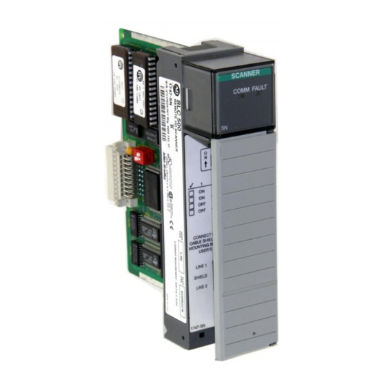
1-18 Overview Hardware Features Below are the scanner’s features. You can find LED information in Chapter 6, Troubleshooting. SCANNER COMM FAULT KBAUD 57.6 115.2 230.4 OFF OFF 230.4 CONNECT ONE END OF CABLE SHIELD TO CHASSIS MOUNTING BOL T . REFER T O USER'S MANUAL. -
Page 28: Leds
Overview 1-19 LEDs Two LEDs allow you to monitor scanner and communication status. FAULT LED - allows you to monitor scanner status. This LED is red. The FAULT LED’s normal state is off; therefore, it is off whenever the scanner is operating properly. COMM LED - allows you to monitor communication with all configured devices. - Page 29 1-20 Overview Catalog Number Device Comments Single Point I/O Adapter Module Single Point I/O 1771-JAB Adapter Module 1771-DCM Direct Communication Module Remote I/O Adapter Module 1778-ASB Direct Communication Module 1747-DCM (1)(5) DL40 Dataliner 2706-xxxx RediPANEL Requires half logical rack configuration if you want to use 2705-xxx stored messages.Requires half logical rack configuration if you want to use stored messages.
-
Page 30: Quick Start For Experienced Users
Chapter Quick Start for Experienced Users This chapter helps you to get started using the RIO Scanner. We base the procedures here on the assumption that you have a basic understanding of SLC 500 products. You must: • understand electronic process control •... -
Page 31: Procedures
Quick Start for Experienced Users Procedures 1. Check the contents of the shipping box. Unpack the module making sure that the contents include: • RIO Scanner (Catalog Number 1747 SN) • termination kit If the contents are incomplete, call your local Allen-Bradley representative for assistance. - Page 32 Quick Start for Experienced Users Never install, remove, or wire modules with ATTENTION power applied to the chassis or devices wired to the module. Make sure system power is off; then insert the scanner module into your 1746 chassis. In this example procedure, local slot 1 is selected.
- Page 33 Quick Start for Experienced Users 7. Enter the number of scanned words. Enter the number of Scanned Input and Output Words using the Specialty I/O and Advanced Setup menus. The default value is 32 I/O words. You can specify less than 32 and reduce the processor scan time by transferring only the part of the input and output image that your application requires.
- Page 34 Quick Start for Experienced Users SCANNER FAULT COMM FAULT LED is off. COMM LED is green. Publication 1747-UM013B-EN-P - January 2005 Artisan Technology Group - Quality Instrumentation ... Guaranteed | (888) 88-SOURCE | www.artisantg.com...
- Page 35 Quick Start for Experienced Users Publication 1747-UM013B-EN-P - January 2005 Artisan Technology Group - Quality Instrumentation ... Guaranteed | (888) 88-SOURCE | www.artisantg.com...
-
Page 36: Installation And Wiring
Chapter Installation and Wiring This chapter contains the information necessary to: • select the baud rate • insert the scanner into the SLC chassis • wire the RIO link • power up the scanner Compliance to European If this product has the CE mark, it is approved for installation within the European Union and EEA regions. -
Page 37: Baud Rate Selection
Installation and Wiring Baud Rate Selection Below are supported baud rates and switch positions: Baud Rate DIP Switch Position Switch 1 Switch 2 57.6K baud 115.2K baud 230.4K baud 230.4K baud The figure below shows the location of the DIP switches on the scanner. -
Page 38: Insertion
Installation and Wiring Disconnect system power before attempting to ATTENTION install, remove, or wire the scanner. Make sure you have set the DIP switches properly IMPORTANT before installing the scanner. Before installation, ensure that your modular SLC IMPORTANT power supply has adequate reserve current capacity. The scanner requires 600 mA @ 5V dc. -
Page 39: Removal
Installation and Wiring Module Release Card Guide Cable Tie Removal 1. Disconnect power. 2. Remove all cabling. 3. Press the releases at the top and bottom of the module and slide the module out of the chassis slot. 4. Cover all unused slots with the Card Slot Filler, Catalog Number 1746-N2. -
Page 40: Rio Link Wiring
Installation and Wiring RIO Link Wiring The scanner is connected to other devices on the RIO link in a daisy chain (serial) configuration. There are no restrictions governing the space between each device, provided the maximum cable distance (Belden 9463) is not exceeded. A 1/2 watt terminating resistor (included with the module) must be attached across line 1 and line 2 of the connectors at each end (scanner and last physical device) of the RIO link. -
Page 41: New Installations
Installation and Wiring Terminating Resistor Last Physical RIO Scanner Device End RIO Link Connector RIO Link Terminating Connector Resistor Scanner End LINE 1 _______ SHIELD _____ LINE 2 _______ Line 1 ± Blue Shield ± Shield Line 2 ± Clear Shield Drain Wire Chassis For Series A... -
Page 42: For Series A Scanner Retrofits
Installation and Wiring The RIO cable shield must be grounded at the IMPORTANT scanner end only. For Series A Scanner Retrofits To eliminate the need to strip the cable back, follow these steps: 1. Attach the shield wire and a short piece of #20 AWG wire (dotted line) to the shield lug of the RIO Link Connector. -
Page 43: Scanner Operation
Installation and Wiring 2. Make sure you have configured your SLC processor and downloaded an application program. (Refer to chapter 4.) 3. Make sure power is applied to all devices on the RIO link. Scanner Operation Below is a description of the scanner’s operation at power up, run mode, and when changing from run mode to program or test mode. -
Page 44: Status Leds
Installation and Wiring If you are using Block Transfer (BT) IMPORTANT functionality, BTs may not function on adapters in Hold Last State settings. Refer to each device’s user manual for information on BTs and Hold Last State settings. Status LEDs The scanner has two LEDs that indicate its operating status, FAULT and COMM. - Page 45 3-10 Installation and Wiring Publication 1747-UM013B-EN-P - January 2005 Artisan Technology Group - Quality Instrumentation ... Guaranteed | (888) 88-SOURCE | www.artisantg.com...
-
Page 46: Understanding Remote Input And Output Image Files
Chapter Scanner Configuration and Programming This chapter contains information necessary to: • understand remote I/O image files • understand RIO configuration using G files • control and view RIO devices using the M0 and M1 files • understand slot addressing •... - Page 47 Scanner Configuration and Programming SN Series B Scanner (RIO Master) Note that some RIO devices (e.g., Scanner Input and Output Images 1771) use octal bit numbers. Output Image Input Image Bit Number Octal Bit Number Octal Bit Number Decimal Bit Number Decimal Word 0 Word 0 Word 1...
- Page 48 Scanner Configuration and Programming e = slot number of the SLC chassis containing the scanner Bit Number (decimal) SLC Input File Address I:e.0 Logical Rack 0 Group 0 Word 0 I:e.1 Logical Rack 0 Group 1 Word 1 I:e.2 Logical Rack 0 Group 2 Word 2 Logical I:e.3...
-
Page 49: Rio Configuration Using G Files
Scanner Configuration and Programming RIO Configuration Using G When you program your SLC system you use the G file to configure the scanner’s I/O image file. Your scanner’s G file configuration is Files based on the devices that you have on the RIO link. G file configuration consists of setting logical device starting addresses and the logical device image size of each physical device/adapter with which the scanner communicates. - Page 50 Scanner Configuration and Programming configuration. The G file consists of five words which are described below. Word 0 - contains scanner information for the SLC processor. Your programming device automatically sets up Word 0. Do not attempt to alter word 0. The term “primary”...
- Page 51 Scanner Configuration and Programming Setting device addresses in word 3 of the G file IMPORTANT configures the system to operate in the complementary I/O mode. Not setting device addresses in word 3 causes the system to operate only in the primary/normal mode. If you wish to operate in the complementary mode and you only have primary devices configured, word 3 of the G file must be set to a decimal “1,”...
-
Page 52: Rules For Configuring The Scanner
Scanner Configuration and Programming Rules for Configuring the Scanner General • The smallest portion of the scanner’s I/O image that can be allocated to a single RIO device is two logical groups (1/4 logical rack). • If a device is configured in word 1, there must be image allocated to it in word 2. - Page 53 Scanner Configuration and Programming • If there is at least one primary device configured in G file words 1 and 2, words 3 and 4 can both be zero, or the G file size can be set to 3 (complementary mode not selected). •...
- Page 54 Scanner Configuration and Programming G File Bit Number I/O Mix, Word 0 RIO Logical Rack 3 RIO Logical Rack 2 RIO Logical Rack 1 RIO Logical Rack 0 Starting Logical Group Starting Logical Group Starting Logical Group Starting Logical Group Primary/Normal Logical Device Address, Word 1 RIO Rack 3...
- Page 55 4-10 Scanner Configuration and Programming Illegal Configuration Examples Having a primary device configured at Logical Rack 1, Logical Group 2 (bit 5) would be illegal since this image space is already being used by a complementary device. Having a complementary device configured at Logical Rack 10, Logical Group 2 (bit 9) would also be illegal since this image space is already being used by a primary device.
- Page 56 Scanner Configuration and Programming 4-11 e = slot number of the SLC chassis containing the scanner Bit Number (decimal) SLC Input File Address I:e.0 Logical Rack 0 Group 0 Word 0 I:e.1 Logical Rack 0 Group 1 Word 1 I:e.2 Logical Rack 0 Group 2 Word 2 Logical...
-
Page 57: Considerations When Configuring Remote I/O
4-12 Scanner Configuration and Programming e = slot number of the SLC chassis containing the scanner Bit Number (decimal) SLC Input File Address Logical Rack 8 Group 0 Word 0 I:e.0 Logical Rack 8 Group 1 Word 1 I:e.1 Logical Rack 8 Group 2 Word 2 I:e.2 Logical Rack 8 Group 3... -
Page 58: Crossing Logical Rack Boundaries
Scanner Configuration and Programming 4-13 • The address and size of the devices you list in the G file must match the settings of each RIO device. Crossing Logical Rack Boundaries You express remote I/O image boundaries in an even number of groups. -
Page 59: Understanding M Files
4-14 Scanner Configuration and Programming When the scanner image assigned to an adapter is more than one logical device, the scanner sees the single physical device as multiple logical devices on the RIO link. The scanner communicates with each logical device independently, even if the logical devices are all assigned to one adapter. - Page 60 Scanner Configuration and Programming 4-15 Appendix B. You can find M file information relating to Block Transfer operations in Chapter 5, Block Transfer. Rung 2:0 To decrease program scan time, copy the first four words of the M1 File to a binary file and use these addresses throughout the program to access block transfer done, error, data, etc.
-
Page 61: M0 Control File Description
4-16 Scanner Configuration and Programming M0 Control File Description You can control the operation of individual devices on the RIO link with M0 word 8 through M0 word 27 (M0:e.8 through M0:e.27). Through your application program, you can use the M0 file to: •... -
Page 62: M0 File - Rio Device Inhibit Control
Scanner Configuration and Programming 4-17 M0 (Control) File - RIO Device Control Words Bit Number M0:e.8 Logical Rack 0 Device Inhibit Word 8 Device M0:e.9 Logical Rack 1 Device Inhibit Word 9 Inhibit M0:e.10 Logical Rack 2 Device Inhibit Word 10 Control M0:e.11 Logical Rack 3 Device Inhibit Word 1 1... -
Page 63: M0 File - Rio Device Reset Control
4-18 Scanner Configuration and Programming When the processor enters the Run mode, the scanner Default: automatically inhibits any device not configured in the G file (bit set to 1). Attempting to inhibit an unconfigured device has no effect. M0 (Control) File W ords 8 through 11 Starting Group Defined Bit Number (decimal) -
Page 64: M0 File - Remote Output Reset Control
Scanner Configuration and Programming 4-19 address will not force a reset. To remove the reset condition, reset the bit (corresponding to the device logical starting address) to 0. See the mode table on page 4-22. The SLC processor resets all bits in this field to 0 when it Default: enters Run or Test mode. - Page 65 4-20 Scanner Configuration and Programming Setting the bit to 1 will command all outputs off (regardless of the device’s Hold Last State setting). Only the device’s logical starting address bit matters. Setting other bits has no effect. Bits 0 to 3 correspond to I/O group locations within logical racks 0, 1, 2, and 3.
-
Page 66: Device Reset And Remote Output Reset Considerations
Scanner Configuration and Programming 4-21 Device Reset and Remote The 1747-SN Scanner Device Reset words (M0:e.16 to M0:e.19) and the Remote Output Reset words (M0:e.24 to M0:e.27) operate in Output Reset conjunction with each RIO device to determine the state of that RIO Considerations device’s outputs. - Page 67 4-22 Scanner Configuration and Programming Example 2 - Once the SLC processor is in Run mode, the bits in the Remote Output Reset word have no effect on the RIO link device’s outputs. Setting the appropriate bits in the Device Reset Word to 1 instructs the RIO link device to reset its outputs.
-
Page 68: M1 Status File Description
Scanner Configuration and Programming 4-23 M1 Status File Description M1 file words 0 through 47 contain the status of all devices on the scanner’s RIO link. M1 is a read only file; do not write to this file. Words 0 to 47 of the M1 file provide the following information: •... -
Page 69: Rio Baud Rate Status
4-24 Scanner Configuration and Programming Device Fault bit. If the Communications Attempted bit is 1, the Enabled Device Fault bit is valid. M1 (Status) File W ord 0 Bit Number (decimal) M1 File General Communication Status Word, Word 0 M1:e.0 Communications Enable Device Attempted... -
Page 70: Logical Device Image Size Status
Scanner Configuration and Programming 4-25 M1 (Status) File - W ord 8 Bit Number (decimal) M1 File Primary Logical Device Address, Word 8 M1:e.8 G File - W ord 1 Starting Group Starting Group Starting Group Starting Group Primary Logical Device Address, Word 1 RIO Logical Rack 3 RIO Logical Rack 2 RIO Logical Rack 1... -
Page 71: Active Device Status
4-26 Scanner Configuration and Programming Word 4 - provides status/feedback of the logical device image size you configure in word 4 of the G file (complementary devices). A bit set to 1 shows the logical image size of each logical device. Writing to word M1 file word 4 will not alter the contents of the G file. -
Page 72: Logical Device Fault Status
Scanner Configuration and Programming 4-27 When a primary device is inhibited, its IMPORTANT complementary device is also inhibited. A complementary device cannot be exclusively inhibited. M1 (Status) File - W ord 5 Bit Number (decimal) RIO Rack 1 1 RIO Rack 10 RIO Rack 9 RIO Rack 8 Starting Group... -
Page 73: Rio Status Example
4-28 Scanner Configuration and Programming M1 (Status) File Primary/Normal Device Fault Status Bit Number (decimal) RIO Rack 3 RIO Rack 2 RIO Rack 1 RIO Rack 0 Starting Group Starting Group Starting Group Starting Group M1 File Primary Device Address, Word 8 M1:e.8 Primary Device Size, Word 9 M1:e.9... - Page 74 Scanner Configuration and Programming 4-29 • M1:e.3 is an image of word 3 (complementary logical device address) of the G file. • M1:e.9 is an image/copy of word 2 (primary/normal logical device size) of the G file. • M1:e.4 is an image/copy of word 4 (complementary logical device size) of the G file.
-
Page 75: Rio Communication Retry Counter (M1:E.16 -47)
4-30 Scanner Configuration and Programming M1 (Status) File Complementary Bit Number (decimal) M1 File Status Word, Word 0 M1:e.0 Baud Rate, Word 2 M1:e.2 RIO Logical RIO Logical RIO Logical RIO Logical Rack 1 1 Rack 10 Rack 9 Rack 8 Complementary Device Starting Address, Word 3 M1:e.3 Complementary Device Image Size, Word 4... - Page 76 Scanner Configuration and Programming 4-31 Your SLC control program cannot initialize/clear retry IMPORTANT counters. Retry Counter Example for Primary Devices The scanner’s I/O image tables are configured as shown with M1 status files displaying the corresponding retry counters: G File - P rimary Bit Number RIO Logical Rack 3 RIO Logical Rack 2...
-
Page 77: Understanding Slot Addressing
4-32 Scanner Configuration and Programming M1:e.32 - communication retry counter for RIO logical rack 8, group 0 M1:e.33 - not used in this example M1:e.34 - not used in this example M1:e.35 - not used in this example M1:e.36 - communication retry counter for RIO logical rack 9, group 0 M1:e.37 - not used in this example M1:e.38 - not used in this example M1:e.39 - not used in this example... -
Page 78: Slc/Scanner Configuration
Scanner Configuration and Programming 4-33 2-Slot Two slots are addressed as one logical group. Addressing Input Image Output Image Remote Chassis Slot 2 Slot 1 Slot 2 Slot 1 1-Slot One slot is addressed as one logical group. Addressing Input Image Output Image Remote Chassis Slot 1... - Page 79 4-34 Scanner Configuration and Programming 2. Assign the scanner to a physical slot in the SLC processor’s chassis by selecting Scanner from the list. If the scanner selection is not available, select OTHER from the I/O Configuration Screen and enter the Code ID number: 13608. 3.
-
Page 80: Rio Block Transfer Theory Of Operation
Chapter RIO Block Transfer This chapter contains the following information: • RIO block transfer theory of operation • RIO block transfer general functional overview • scanner’s block transfer buffer layout • detailed operation of RIO block transfer • RIO block transfer application considerations •... - Page 81 RIO Block Transfer RIO Block Transfer Theory of Operation - Path of Block Transfer Chassis Backplane Refer to the diagrams on the following pages for more details on BTR and BTW sequence of operation. Processor Scanner Block Transfer Write (BTW) data travels from the Files SLC processor across the chassis backplane via M Files...
- Page 82 RIO Block Transfer The steps below detail a successful Block Transfer Read (BTR). 1. The M0 file contains BTR control information which controls (initiates) the scanner BTR operation. (Refer to the Block Transfer Buffer Layout section for details on control information.) 2.
- Page 83 RIO Block Transfer RIO Block Transfer Theory of Operation - Block Transfer Write (BTW) In this example, Logical Rack 3, Logical Group 7, Logical Slot 1 is used. Slot 0 Slot 0 Slot 1 Slot 1 Input Image Output Image Group 0 Word 0 Chassis Backplane...
-
Page 84: Using Block Transfer Instructions (Btr And Btw)
RIO Block Transfer Using Block Transfer Block transfer instructions are supported by SLC 5/03 (OS302, Series C), SLC 5/04 (OS401, Series C) and SLC 5/05 (OS501, Series C) Instructions (BTR and BTW) and higher processors only. For application examples for block transferring with SLC 5/02 processors, refer to Appendix D. -
Page 85: Parameters For Btr And Btw
RIO Block Transfer Parameters for BTR and BTW The instructions have the following parameters: • Data File - The address in the SLC processor’s data file containing the BTW or BTR data. • BTR/BTW Buffer File - Block transfer buffer file address; i.e. -
Page 86: Control Status Bits
RIO Block Transfer Table 5.1 Control Block Structure Word 0 Rack Group Slot Word 1 Requested word count Word 2 Transmitted word count/Error code Control Status Bits To use the BTR and BTW instructions correctly, examine the instruction’s control and status bits stored in the control structure. These bits are mapped to bits in word 0 of the control block structure. - Page 87 RIO Block Transfer Successful Block Transfer Read/Write The illustration on the previous page shows a successful BT operation. 1. The SLC control program copies new data to the data file (BTW only) and solves the BT rung true, which sets the enable (EN) bit.
- Page 88 RIO Block Transfer Table 5.2 Control and Status Bit Descriptions Control/Status Bit Description Enable EN (bit 15) Block Transfer Enabled - (EN = Enabled). The processor sets/resets this bit depending on the rung state (true/false). The processor sends the enable bit to the RIO scanner when the BTR/BTW instruction is scanned.
- Page 89 5-10 RIO Block Transfer Transmitted Word Count/Error Code, Word 2 (DLEN) Transmitted Word Count is the status of the actual number of BTW words sent or the number of BTR words received. The processor uses this number to verify the transfer. This number should match the requested word count (unless the transmitted word count is zero).
-
Page 90: Instruction Operation
RIO Block Transfer 5-11 Instruction Operation 1. The scanner processes the BTR/BTW when it detects that the SLC control program rung, which contains the BTR/BTW, goes true. If the RIO scanner detects any problem at this point (such as invalid block transfer control field, or unconfigured device), the control structure word 2 fills with the error code and the ER bit (bit 12) is set. -
Page 91: Programming Examples
5-12 RIO Block Transfer 5. When the RIO scanner detects that the EN bit cleared, it then clears the EW, ST and DN or ER bits, as well as the Transmitted Word Count/Error Code. This ensures that the status bits in the control block are not reflecting the results of the previous block transfer operation. - Page 92 RIO Block Transfer 5-13 Figure 5.2 Directional Figure 5.3 Directional Repeating Publication 1747-UM013B-EN-P - January 2005 Artisan Technology Group - Quality Instrumentation ... Guaranteed | (888) 88-SOURCE | www.artisantg.com...
- Page 93 5-14 RIO Block Transfer Figure 5.4 Directional Continuous Figure 5.5 Bi-directional Continuous Publication 1747-UM013B-EN-P - January 2005 Artisan Technology Group - Quality Instrumentation ... Guaranteed | (888) 88-SOURCE | www.artisantg.com...
- Page 94 RIO Block Transfer 5-15 Figure 5.6 Bi-directional Alternating Figure 5.7 Bi-directional Alternating Repeating Publication 1747-UM013B-EN-P - January 2005 Artisan Technology Group - Quality Instrumentation ... Guaranteed | (888) 88-SOURCE | www.artisantg.com...
-
Page 95: Comparison To The Plc-5 Btr And Btw
5-16 RIO Block Transfer Comparison to the PLC-5 BTR and BTW Block Transfer Reads and Writes in SLC processors are quite similar to the instructions in the PLC-5. However, some differences exist between them, as shown in Table 5.5 on page 5-16. Table 5.5 Block Transfer Comparison PLC-5 Control Block... -
Page 96: Chapter 6 Troubleshooting
Chapter Troubleshooting This chapter provides information for troubleshooting the RIO scanner. Troubleshooting The FAULT LED is off whenever the scanner is operating properly. The COMM LED state is valid only when the FAULT LED is off. When the scanner’s LEDs change state, use the following table to isolate the cause. -
Page 97: Error Codes
Troubleshooting Error Codes The SLC processor reports error codes in word 6 of the SLC processor status file. Below are the format of the status word and applicable error codes. Slot Number Error Code 62H - G File is missing 01H to 1EH 63H - Invalid user configuration 64H - Duplicate node fault... -
Page 98: Scanner Operating Specifications
Appendix Specifications This appendix provides scanner and system specifications, as well as throughput information. Topics include: • scanner operating specifications • network specifications • throughput introduction • calculating throughput Scanner Operating Specifications Backplane Current Consumption 600 mA @ 5V dc Operating Temperature +32°F to 140°F (0°C to +60°C) Storage Temperature... -
Page 99: Throughput Introduction
Specifications Table A.2 DIP Switch Position for Baud Rate Selection Baud Rate DIP Switch Position Switch 1 Switch 2 57.6K baud 115.2K baud 230.4K baud 230.4K baud Throughput Introduction RIO throughput is defined as the time between when an input event occurs at an I/O module in an RIO chassis to when an output event occurs at an I/O module within the same RIO chassis. -
Page 100: Calculating Throughput
Specifications Processor Scan Scanner Scan ASB Backplane Scan Scanner ASB Module I/O Module Processor I/O Module RIO Scan SLC Local Chassis Outputs to Modules Remote Chassis Remote Expansion Chassis Inputs from Modules Outputs from Modules Inputs to Modules Output Device Input Device When the SLC control program detects that the remote input has been turned on (via the scanner output image), it activates the remote... - Page 101 Specifications To calculate T dm-nbt throughput, substitute values for the variables in the formula above. Locate these values in the following documents: Variable Variable Description Location of Variable The total processor scan Measured or estimated time (ms) The total RIO scan time (ms) see the section RIO Scan Time Calculation (T RIO ) on page A-4 The adapter throughput...
- Page 102 Specifications Example Discrete I/O Throughput without Block Transfers Present An SLC 5/03 is controlling an RIO link running at 115.2K baud that has the following adapters: • One 1747-ASB module is configured as a 1/2 logical rack starting at logical rack 0. I/O chassis slot 1 contains 1746-IB16, 16 point input module I/O chassis slot 2 contains 1746-OB16, 16 point output module •...
- Page 103 Specifications T RIO = 1(4.0 ms) + 2(5.5 ms) + 3(3.5 ms) T RIO = 25.5 ms 3. Find T SNo on page A-14 in the table T SNo without M0 File Writes (Normal Mode). For this example T upd > T hold , and there are 4 logical racks configured.
-
Page 104: Present
Specifications Variable Variable Description Location of Variable The total processor scan Measured or estimated time (ms) The total RIO scan time (ms) see the section RIO Scan Time Calculation (T RIO ) on page A-4 Additional time due to see the section Determining sending any BT data on the T btx on page A-8 RIO link. - Page 105 Specifications Number of Normal Mode Complementary Mode Logical Racks All Baud 57.6K baud 115.2K baud 230.4K baud Configured Rates 1 Logical Rack 16.0 19.0 24.0 32.0 2 Logical Racks 19.0 23.0 27.0 36.0 3 Logical Racks 22.0 26.0 30.0 39.0 4 Logical Racks 25.0 28.0...
- Page 106 Specifications Adapter #1 (1747-ASB module): • starting logical rack 0, logical group 0 • 12 logical groups (1 1/2 logical racks) • one 8 word and two 4 word BT write/read modules in logical rack 0 • one 2 word BT write/read module in logical rack 1 Adapter #2 (1771-ASB module): •...
-
Page 107: Block Transfer Throughput
A-10 Specifications T dm-bt = 2(25.0) + 2T RIO + 2T btx + 9.0 + 22.0 + 5.0 + 10.0 + 1.0 2. Calculate the total RIO scan time (T RIO ). Locate the baud rate (115.2K) and adapter size which is found in the table on page B-4. - Page 108 Specifications A-11 shown on page, where a BT is retriggered automatically upon each completion. BT throughput is always slower than discrete data transfer. Completing a BT is dependent on the time involved for the: • SLC control program to enable the BT via an M0 file write •...
- Page 109 A-12 Specifications Variable Variable Description Location of Variable Time to perform M0 file write to T M0 appendix B enable BT Scanner Output Delay time with see the section Determining T SNo-bt BTs present. There must be an T SNo-bt on page output delay time added for each BT buffer that is being used since the scanner...
-
Page 110: Rio Scanner Output Delay Time (Tsno) Tables
Specifications A-13 RIO Scanner Output Delay Time (T SNo ) Tables The tables provided in this section show the maximum scanner output delay time (T SNo ) for specific applications. T SNo is dependent on the following: • processor scan time, or time between immediate outputs (if no BTs are present) •... - Page 111 A-14 Specifications number of logical devices on the RIO network affects only T RIO , and only affects T SNo when additional logical racks are used. When complementary mode is selected, the number of configured racks is also determined by the number of primary or complementary racks configured, but not by both.
- Page 112 Specifications A-15 T SNo with M0 File Writes (No Block Transfers) Normal Mode Number of Logical All Baud Rates Racks Configured ≤ T if T if T >T hold hold hold 1 Logical Rack 2 Logical Rack 10.0 3 Logical Rack 12.0 10.0 4 Logical Rack...
- Page 113 A-16 Specifications Publication 1747-UM013B-EN-P - January 2005 Artisan Technology Group - Quality Instrumentation ... Guaranteed | (888) 88-SOURCE | www.artisantg.com...
-
Page 114: Appendix B M0 - M1 Files
Appendix M0 - M1 Files and G Files This appendix contains important information about M0-M1 files and G files. The information is general in nature and supplements specific information contained in earlier chapters of this manual. M0 - M1 Files M0 and M1 files are data files that reside in specialty I/O modules only. -
Page 115: Addressing M0-M1 Files
M0 - M1 Files and G Files Addressing M0-M1 Files The addressing format for M0 and M1 files is below: Mf:e.s/b Where M = module = file type (0 or 1) slot (1-30) word (0 to max. supplied by module) = bit (0-15) Restrictions on Using M0-M1 Data File Addresses M0 and M1 data file addresses can be used in all instructions except... - Page 116 M0 - M1 Files and G Files Mf:e.s Mf:e.s Mf:e.s Mf:e.s Mf:e.s f = file (0 or 1) When you are monitoring the ladder program in the Run or Test mode, the display does not show these When you are monitoring the ladder program in the Run or Test mode, the instructions as being true when the processor evaluates them as true.
-
Page 117: Transferring Data Between Processor Files And M0 Or M1 Files
M0 - M1 Files and G Files Transferring Data Between Processor Files and M0 or M1 Files The processor does not contain an image of the M0 or M1 file. As a result, you must edit and monitor M0 and M1 file data via instructions in your ladder program. - Page 118 M0 - M1 Files and G Files Processor Instruction Type Access Time per Access Time per Bit Instruction or Multi-Word Word of Data Instruction SLC 5.02 Series B 1930 µs 1580 µs plus 670 µs All Types per word SLC 5/02 Series C 1160 µs 950 µs plus 400 µs All Types...
- Page 119 M0 - M1 Files and G Files COPY FILE Source #B3:0 Dest #M0:1.0 Length If you are using a SLC 5/02 Series B processor, add 1580 µs plus 670 µs per word of data addressed to the M0 or M1 file. As shown above, 34 words are copied from #B3:0 to M0:1.0.
-
Page 120: Minimizing The Scan Time
M0 - M1 Files and G Files Minimizing the Scan Time You can keep the processor scan time to a minimum by economizing on the use of instructions addressing the M0 or M1 files. For example, XIC instruction M0:2.1/1 is used in rungs 1 and 2 of the figure below, adding approximately 2 ms to the scan time if you are using a SLC 5/02 Series B processor. -
Page 121: Capturing M0-M1 File Data
M0 - M1 Files and G Files Capturing M0-M1 File Data The first two ladder diagrams in the last section illustrate a technique allowing you to capture and use M0 or M1 data as it exists at a particular time. In the first figure, bit M0:2.1/1 could change state between rungs 1 and 2. -
Page 122: G Files
M0 - M1 Files and G Files This rung is true M0:2.1 for the first scan after powerup to unlatch M0:2.1/1. M0:2.1 M0:2.1 G Files Some specialty I/O modules use G (confiGuration) files (indicated in the specific specialty I/O module user’s manual). These files can be thought of as the software equivalent of DIP switches. - Page 123 B-10 M0 - M1 Files and G Files Figure B.1 I/O Configuration Screen 2. Click the “Adv Config” button to access the next menu. You can edit the number of words in each category. Although, it is recommended to leave them at default values unless specific project considerations require changes.
- Page 124 M0 - M1 Files and G Files B-11 3. Click “Edit G Data” to access the setup screen for the module. Figure 2.3 Scanner G File Configuration Options Once you understand how the modules map Remote I/O locations, this menu is used to set up the Scanner. First select a group number in a logical rack.
- Page 125 B-12 M0 - M1 Files and G Files Figure 2.4 Rack Configurations Once you select the group and type of addressing, the I/O word layout for the group is shown. Publication 1747-UM013B-EN-P - January 2005 Artisan Technology Group - Quality Instrumentation ... Guaranteed | (888) 88-SOURCE | www.artisantg.com...
- Page 126 M0 - M1 Files and G Files B-13 Figure 2.5 Example of a Half-Rack Addressing in Group 1 After all devices have been properly mapped, click OK and the G file is automatically configured. This procedure eliminates the bit by bit process needed to configure the G file with other programming tools.
-
Page 127: Editing G File Data
B-14 M0 - M1 Files and G Files Editing G File Data Data in the G file must be edited according to your application and the requirements of the specialty I/O module. You edit the data offline under the I/O configuration function only. With the decimal and hex/bcd formats, you edit data at the word level: •... -
Page 128: Directions
Appendix RIO Configuration Worksheet This appendix provides a worksheet to help you configure your RIO devices. Directions We recommend that you use a photocopy of the worksheet so you retain a blank worksheet for future applications. SLC Processor Output Image SLC Processor Input Image High Byte Low Byte... - Page 129 RIO Configuration Worksheet SLC Processor Output Image SLC Processor Input Image High Byte Low Byte High Byte Low Byte Bit Number - Decimal Bit Number - Decimal Group 0 Group 0 O:e.0 I:e.0 Group 1 Group 1 O:e.1 I:e.1 Group 2 Group 2 I:e.2 O:e.2...
-
Page 130: Btr And Btw Control Logic Examples
Appendix Block Transfer Examples for Earlier Processors BTR and BTW Control Logic These BTR and BTW instructions are for SLC 5/03, SLC 5/04 and SLC 5/05 or earlier processors with OS302, OS401, OS501 series B or Examples earlier operating systems. Block Transfer Read Control Logic Example Rung 2:0 CONFIGURE THE BTR OPERATION TYPE, LENGTH AND RIO ADDRESS AT POWER-UP. - Page 131 Block Transfer Examples for Earlier Processors Rung 2:3 WHEN A BTR SUCCESSFULLY COMPLETES, BUFFER THE BT DATA AND UNLATCH THE BT ENABLE BIT. ALSO, UNLATCH THE BTR PENDING BIT AND LATCH THE BIT THAT CONTINUES CHECKING THE BTR STATUS UNTIL THE SN MODULE TURNS OFF THE DONE BIT. | VIRTUAL | BTR DONE | BIT...
- Page 132 Block Transfer Examples for Earlier Processors Rung 2:5 WHEN USER LOGIC INITIATES A NEW BTR, LATCH THE ENABLE BIT , AS LONG AS A BTR IS NOT IN PROGRESS. ALSO, LATCH THE BTR PENDING BIT , SO THE BTR STATUS FILE WILL BE READ BY THE LADDER PROGRAM.
-
Page 133: Block Transfer Write Control Logic Example
Block Transfer Examples for Earlier Processors Block Transfer Write Control Logic Example Rung 2:0 CONFIGURE THE BTW LENGTH AND RIO ADDRESS AT POWER-UP. ALSO, BE SURE THE BLOCK TRANSFER OPERATION BIT IS A ”0” INDICATING A BTW. ALL THESE PARAMETERS MUST BE ENTERED PRIOR TO PLACING THE PROCESSOR IN THE RUN MODE. - Page 134 Block Transfer Examples for Earlier Processors Rung 2:4 IF A BTW ERRORS, UNLATCH THE ENABLE BIT, THE BTW PENDING BIT AND BUFFER THE BTW ERROR CODE. ALSO, LATCH THE BIT THAT CONTINUES CHECKING THE BTW STATUS UNTIL THE SN MODULE TURNS OFF THE ERROR BIT. | VIRTUAL | BTW ERROR BUFFER BTW...
-
Page 135: Directional Continuous Block Transfer Example
Block Transfer Examples for Earlier Processors Rung 2:6 MOVE THE VIRTUAL CONTROL WORD TO THE M0 FILE FOR THE SN MODULE WHENEVER A TRANSITION OF THE BTW ENABLE BIT OCCURS. VIRTUAL BTW ENABLE B3:100 +MOV---------------+ | |-+----] [-----+------------------------------------------+MOVE |Source B3:100| | 0000000000000000| | |Dest M0:1.100| |... - Page 136 Block Transfer Examples for Earlier Processors Rung 2:0 CONFIGURE THE BTR OPERATION TYPE, LENGTH AND RIO ADDRESS AT POWER-UP. BIT B3:100/7 MUST BE SET PRIOR TO GOING TO RUN TO INDICATE A BTR OPERATION. | POWER-UP | BIT CONTROL +COP---------------+ | |----] [--------------------------------------------------+COPY FILE |Source #B3:100| |...
- Page 137 Block Transfer Examples for Earlier Processors Rung 2:3 WHEN A BTR SUCCESSFULLY COMPLETES, BUFFER THE BTR DATA AND UNLATCH THE BTR ENABLE BIT. ALSO, UNLATCH THE BTR PENDING BIT AND LATCH THE BIT THAT CONTINUES CHECKING THE BTR STATUS UNTIL THE SN TURNS OFF THE DONE BIT. | VIRTUAL | BTR DONE | BIT...
-
Page 138: Directional Repeating Block Transfer Example
Block Transfer Examples for Earlier Processors Rung 2:5 BLOCK TRANSFER READS WILL EXECUTE CONTINUOUSLY AS LONG AS THE BTR PRECONDITION BIT IS TRUE. | BTR PRE- |VIRTUAL |VIRTUAL |VIRTUAL | CONDITION |BTR ENABLE|BTR DONE |BT ERROR | BIT |BIT |BIT |BIT PENDING |----] [--------]/[--------]/[--------]/[-----------------------+----(L)-----+-|... - Page 139 D-10 Block Transfer Examples for Earlier Processors Rung 2:0 CONFIGURE THE BTR OPERATION TYPE, LENGTH AND RIO ADDRESS AT POWER-UP. BIT B3:100/7 MUST BE SET PRIOR TO GOING TO RUN TO INDICATE A BTR OPERATION. | POWER-UP | BIT CONTROL +COP---------------+ | |----] [--------------------------------------------------+COPY FILE |Source...
- Page 140 Block Transfer Examples for Earlier Processors D-11 Rung 2:3 WHEN A BTR SUCCESSFULLY COMPLETES, BUFFER THE BTR DATA AND UNLATCH THE BTR ENABLE BIT. ALSO, UNLATCH THE BTR PENDING BIT AND LATCH THE BIT THAT CONTINUES CHECKING THE BTR STATUS UNTIL THE SN TURNS OFF THE DONE BIT. | VIRTUAL | BTR DONE | BIT...
-
Page 141: Directional Non-Continuous Block Transfer Example
D-12 Block Transfer Examples for Earlier Processors Rung 2:5 BLOCK TRANSFER READS WILL REPEAT AS FAST AS POSSIBLE AS LONG AS THESE RUNGS ARE SCANNED. | VIRTUAL |VIRTUAL |VIRTUAL | BTR ENABLE|BTR DONE |BT ERROR | BIT |BIT |BIT PENDING |----]/[--------]/[--------]/[----------------------------------+----(L)-----+-| 1615 | VIRTUAL... - Page 142 Block Transfer Examples for Earlier Processors D-13 Rung 2:0 CONFIGURE THE BTR OPERATION TYPE, LENGTH AND RIO ADDRESS AT POWER-UP. BIT B3:100/7 MUST BE SET PRIOR TO GOING TO RUN TO INDICATE A BTR OPERATION. | POWER-UP | BIT CONTROL +COP---------------+ | |----] [--------------------------------------------------+COPY FILE |Source...
- Page 143 D-14 Block Transfer Examples for Earlier Processors Rung 2:3 WHEN A BTR SUCCESSFULLY COMPLETES, BUFFER THE BTR DATA AND UNLATCH THE BTR ENABLE BIT. ALSO, UNLATCH THE BTR PENDING BIT AND LATCH THE BIT THAT CONTINUES CHECKING THE BTR STATUS UNTIL THE SN TURNS OFF THE DONE BIT. | VIRTUAL | BTR DONE | BIT...
- Page 144 Block Transfer Examples for Earlier Processors D-15 Rung 2:5 INITIATE A BTR FOR EACH FALSE-TO-TRUE TRANSITION OF THE USER INPUT. | USER LOGIC | TO | INITIATE A | BTR |----] [------[OSR]-------------------------------------------------------(L)--| 83 | Rung 2:6 WHEN USER LOGIC INITIATES A NEW BTR, LATCH THE ENABLE BIT AS LONG AS A BTR IS NOT IN PROGRESS.
-
Page 145: Bidirectional Continuous Block Transfer Example
D-16 Block Transfer Examples for Earlier Processors Bidirectional Continuous Block Transfer Example The following rungs demonstrate a bidirectional continuous block transfer. The BTR and BTW will each execute as fast as possible, continuously and independently of one another. Rung 2:0 CONFIGURE THE BT OPERATION TYPE, LENGTH AND RIO ADDRESS (R,G,S IN DECIMAL) AT POWER-UP. - Page 146 Block Transfer Examples for Earlier Processors D-17 Rung 2:3 COPY THE BTW STATUS AREA TO AN INTEGER FILE ONLY WHEN A BTW IS IN PROGRESS. THIS STATUS DATA WILL THEN BE USED THROUGHOUT THE PROGRAM AND WILL LIMIT THE NUMBER OF M-FILE ACCESSES. PENDING STATUS +COP---------------+ |...
- Page 147 D-18 Block Transfer Examples for Earlier Processors Rung 2:5 WHEN A BTR SUCCESSFULLY COMPLETES, BUFFER THE BTR DATA AND UNLATCH BOTH THE BTR VIRTUAL ENABLE BIT AND THE BTR PENDING BIT. ALSO, LATCH THE BIT THAT CONTINUES CHECKING THE BTR STATUS UNTIL THE SN MODULE TURNS OFF THE DONE BIT. | VIRTUAL | BTR DONE | BIT...
- Page 148 Block Transfer Examples for Earlier Processors D-19 Rung 2:7 WHEN A BTW SUCCESSFULLY COMPLETES, UNLATCH THE BTW ENABLE BIT AND THE BTW PENDING BIT TO COMPLETE A BTW SEQUENCE. ALSO, LATCH THE BIT THAT CONTINUES CHECKING THE BTW STATUS UNTIL THE SN MODULE TURNS THE DONE BIT OFF. | VIRTUAL | BTW DONE | BIT...
- Page 149 D-20 Block Transfer Examples for Earlier Processors Rung 2:9 THIS RUNG WILL EXECUTE BLOCK TRANSFER READS CONTINUOUSLY, AS FAST AS POSSIBLE. | VIRTUAL |VIRTUAL |VIRTUAL | BTR ENABLE|BTR DONE |BTR ERROR | BIT |BIT |BIT PENDING N7:50 N7:60 N7:60 |----]/[--------]/[--------]/[----------------------------------+----(L)-----+-| | VIRTUAL | BTR ENABLE | | | BIT...
-
Page 150: Bidirectional Alternating Block Transfer
Block Transfer Examples for Earlier Processors D-21 Rung 2:12 MOVE THE VIRTUAL BTW CONTROL WORD TO THE M0 FILE FOR THE SN MODULE WHILE A BTW IS IN PROGRESS, AND CONTINUE DOING SO UNTIL THE ENABLE, DONE AND ERROR BITS ARE ALL TURNED OFF, COMPLETING THE HAND-SHAKE PROCESS. - Page 151 D-22 Block Transfer Examples for Earlier Processors Rung 2:0 CONFIGURE THE BT OPERATION TYPE, LENGTH, AND RIO ADDRESS (R,G,S IN DECIMAL) AT POWER-UP. N7:50/7 MUST BE SET TO A ”1” TO INDICATE A BTR AND N7:53/7 MUST BE A LOGICAL ”0” TO INDICATE A BTW OPERATION. | POWER-UP | BIT CONTROL...
- Page 152 Block Transfer Examples for Earlier Processors D-23 Rung 2:3 COPY THE BTW STATUS AREA TO AN INTEGER FILE ONLY WHEN A BTW IS IN PROGRESS. THIS STATUS DATA WILL THEN BE USED THROUGHOUT THE PROGRAM AND WILL LIMIT THE NUMBER OF M-FILE ACCESSES. PENDING STATUS +COP---------------+ |...
- Page 153 D-24 Block Transfer Examples for Earlier Processors Rung 2:6 WHEN A BTR UNSUCCESSFULLY COMPLETES, BUFFER THE BTR ERROR CODE AND UNLATCH THE BTR ENABLE BIT AND THE BTR PENDING BIT. ALSO, LATCH THE CHECK BTR STATUS BIT IN ORDER TO CONTINUE READING THE STATUS INFORMATION FROM THE SCANNER UNTIL IT TURNS THE ERROR BIT OFF, COMPLETING THE HAND-SHAKE PROCESS.
- Page 154 Block Transfer Examples for Earlier Processors D-25 Rung 2:8 THIS RUNG AND THE NEXT RUNG WILL TOGGLE BETWEEN EXECUTING A BTR AND A BTW WHILE THE USER SUPPLIED BT PRECONDITION BIT (B3:0/11 IS USED IN THIS EXAMPLE) IS TRUE. | BT |VIRTUAL |VIRTUAL |VIRTUAL...
- Page 155 D-26 Block Transfer Examples for Earlier Processors Rung 2:10 MOVE THE VIRTUAL BTR CONTROL WORD TO THE M0 FILE FOR THE SN MODULE WHILE A BTR IS IN PROGRESS, AND CONTINUE DOING SO UNTIL THE ENABLE, DONE AND ERROR BITS ARE ALL TURNED OFF.
-
Page 156: Bidirectional Alternating Repeating Block Transfer
Block Transfer Examples for Earlier Processors D-27 Bidirectional Alternating Repeating Block Transfer The following rungs demonstrate a bidirectional alternating repeating block transfer. Using these rungs ensures the block transfer requests are executed in the order in which they are sent to the queue. This example also ensures that the BTR and BTW repeatedly alternate. - Page 157 D-28 Block Transfer Examples for Earlier Processors Rung 2:2 UNLATCH THE BIT THAT CONTINUES TO CHECK THE BTR STATUS. WHEN A BTR IS COMPLETE, THE DONE OR ERROR BIT IS SET. THE LADDER PROGRAM MUST THEN UNLATCH THE ENABLE BIT, THEN WAIT FOR THE SN MODULE TO TURN OFF THE DONE/ERROR BIT BEFORE ANOTHER BTR TO THE SAME M-FILE LOCATION CAN BE INITIATED.
- Page 158 Block Transfer Examples for Earlier Processors D-29 Rung 2:5 WHEN A BTR SUCCESSFULLY COMPLETES, BUFFER THE BTR DATA AND UNLATCH BOTH THE BTR VIRTUAL ENABLE BIT AND THE BTR PENDING BIT. ALSO, LATCH THE BIT THAT CONTINUES CHECKING THE BTR STATUS UNTIL THE SN MODULE TURNS OFF THE DONE BIT. | VIRTUAL | BTR DONE | BIT...
- Page 159 D-30 Block Transfer Examples for Earlier Processors Rung 2:7 WHEN A BTW SUCCESSFULLY OR UNSUCCESSFULLY COMPLETES, UNLATCH THE BTW ENABLE BIT AND THE BTW PENDING BIT TO COMPLETE A BTW SEQUENCE. ALSO, LATCH THE BIT THAT CONTINUES CHECKING THE BTW STATUS UNTIL THE SN MODULE TURNS THE DONE/ERROR BIT OFF.
- Page 160 Block Transfer Examples for Earlier Processors D-31 Rung 2:9 | VIRTUAL |VIRTUAL |VIRTUAL |VIRTUAL | BTR ENABLE|BTW ENABLE|BTW DONE |BTW ERROR | BIT |BIT |BIT |BIT BTW DATA N7:50 N7:53 N7:64 N7:64 +COP---------------+ |----]/[--------]/[--------]/[--------]/[-------------+-+COPY FILE +-+-| | |Source #N7:10| | | | |Dest #M0:1.210| | | | |Length...
- Page 161 D-32 Block Transfer Examples for Earlier Processors Rung 2:11 MOVE THE VIRTUAL BTW CONTROL WORD TO THE M0 FILE FOR THE SN MODULE WHILE A BTR IS IN PROGRESS, AND CONTINUE DOING SO UNTIL THE ENABLE, DONE AND ERROR BITS ARE ALL TURNED OFF, COMPLETING THE HAND-SHAKE PROCESS.
- Page 162 Glossary The following terms are used throughout this manual. Refer to the Allen-Bradley Industrial Automation Glossary, Publication Number AG-7.1, for a complete guide to Allen-Bradley technical terms. Adapter Any physical device that is a slave on the RIO link. Adapter Image That portion of the scanner image assigned to an individual adapter.
- Page 163 Glossary Extended Node Capability Functionality that allows you to use an 82 Ohm termination resistor at both ends of the RIO link for all baud rates. This functionality also allows for up to 32 adapters to be connected to the RIO link. G file The SLC file used to configure the scanner.
- Page 164 Glossary Logical Slot A logical slot consists of one input and one output byte within a logical group. A byte consists of 8 bits, each bit represents one terminal on a discrete I/O module. M files The SLC M0 and M1 data files that reside in the scanner. M files contain RIO network status (M1) and control (M0) information.
- Page 165 Glossary RIO Discrete Transfer The exchange of image data between the scanner and adapter. RIO discrete transfers occur continuously whenever the scanner and adapter are communicating on the RIO link. RIO Link An Allen-Bradley communication system supporting high-speed serial transfer of Remote I/O (RIO) control information. This link consists of one master and one or more slaves.
- Page 166 Index Numerics scanner I/O image configuration 1/2-slot addressing G file 1-14 complementary I/O general rules 1-slot addressing rules concerning complimentary I/O 1-13 complementary I/O 4-33 configuring scanner 2-slot addressing considerations 1-12 complementary I/O configuration 1-17 complementary I/O 4-12 configuring remote I/O 4-21 device and remote output reset creating logical devices...
- Page 167 Index fault status table troubleshooting 1-19 link specification logical physical G file 4-25 logical device image size B-14 editing G file data logical rack word 0 4-13 crossing logical rack boundaries word 1, primary logical device address logical rack boundaries 4-13 crossing word 2, primary logical image size...
- Page 168 Index interaction with adapters operating with SLCs noise immunity output delay time with block transfer A-13 without block transfer scanning remote I/O operation scanner I/O image run mode concepts startup selecting operation modes baud rate changing setting up scanner 4-33 overview G file M files...
- Page 169 Index G file word 2, primary logical image size understanding G file I/O image files word 3, secondary logical device 4-32 slot addressing address G file word 4, secondary logical image size word 0 G file words 24 through 27 G file 4-19 word 1, primary logical device address...
- Page 170 Index Publication 1747-UM013B-EN-P - January 2005 Artisan Technology Group - Quality Instrumentation ... Guaranteed | (888) 88-SOURCE | www.artisantg.com...
- Page 171 Artisan Technology Group - Quality Instrumentation ... Guaranteed | (888) 88-SOURCE | www.artisantg.com...
-
Page 172: Rockwell Automation Support
Publication 1747-UM013B-EN-P - January 2005 PN XXXXXX-XX Supersedes Publication 1747-6.6 - July 1996 Copyright © 2005 Rockwell Automation, Inc. All rights reserved. Printed in the U.S.A. Artisan Technology Group - Quality Instrumentation ... Guaranteed | (888) 88-SOURCE | www.artisantg.com... - Page 173 Artisan Technology Group is your source for quality new and certified-used/pre-owned equipment SERVICE CENTER REPAIRS WE BUY USED EQUIPMENT • FAST SHIPPING AND DELIVERY Experienced engineers and technicians on staff Sell your excess, underutilized, and idle used equipment at our full-service, in-house repair center We also offer credit for buy-backs and trade-ins •...
Need help?
Do you have a question about the Allen-Bradley 1747-SN and is the answer not in the manual?
Questions and answers