Table of Contents
Advertisement
Quick Links
Advertisement
Table of Contents

Related Manuals for SiFive HiFive Unleashed


Summary of Contents for SiFive HiFive Unleashed
- Page 1 SiFive HiFive Unleashed Getting Started Guide v1p2 © SiFive, Inc.
- Page 2 SiFive does not assume any liability rising out of the application or use of any product or circuit, and specifically disclaims any and all liability, including without limitation indirect, incidental, spe- cial, exemplary, or consequential damages.
-
Page 3: Table Of Contents
......................6 Boot and Run ......................11 ....................11 Connecting with ssh ..................11 Connecting with USB console ................. 12 Knobs on the HiFive Unleashed ....................12 HiFive Unleashed Boot Firmware Update ....................14 Software Development Flow ................15 ....................15 Supported Platforms ..........15... - Page 4 ................... 24 MicroSD Card Connector ....................... 24 JTAG Connector...
-
Page 5: Introduction
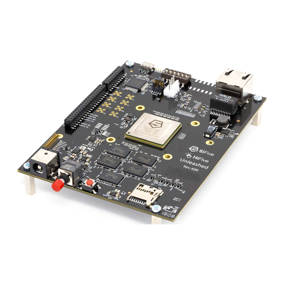
Chapter 1 Introduction HiFive Unleashed is a Linux development platform for SiFive’s Freedom U540 SoC, the world’s first 4+1 64-bit multi-core Linux-capable RISC-V SoC. The HiFive Unleashed has 8GB DDR4, 32MB QuadSPI Flash, a Gigabit Ethernet port, and a MicroSD card slot for more external stor- age. -
Page 6: Required Hardware
12V DC Power Wall Adapter The HiFive Unleashed Development Kit requires an external 12V, 2A power supply. When not powering directly from the FMC expansion module, a 12V DC Wall Adapter with a 5.5 outer diameter, 2.5 mm center-positive barrel plug, must be plugged into DC power jack on the HiFive Unleashed. -
Page 7: Optional Hardware
Chapter 3 Optional Hardware Ethernet Cable HiFive Unleashed Development Kit has an RJ45 Ethernet port that enables the FU540-C000 to connect to an 10/100/1000 Base-T network. FMC Expansion Carrier Card Additional functionality can be added to the HiFive Unleashed Development Kit through the FMC connector. -
Page 8: Board Setup
To prepare the board for use, follow these steps: • Unplug the HiFive Unleashed and switch the power off (red button sticking out). The board is still powered even when the switch is off, so handle with care whenever power is applied. - Page 9 • Ensure the fan is plugged in. • Set all pins in the DIP-switch block to the LEFT. The ON position=0; therefore, this sets MSEL to mode 1111. See the boot modes table in next section for more information on MSEL.
- Page 11 • Insert an SD-card programmed with bbl+linux. The github repository sifive/ produces an image suitable for writing to a partition with GUID type freedom-u-sdk 2E54B353-1271-4842-806F-E436D6AF6985 • If available, connect the board to a network switch. The board will run DHCP on boot and start an ssh server.
- Page 12 . The second 115200Hz provides JTAG suitable for use with openocd. • Plug in the HiFive Unleashed; the fan should begin to spin. • Turn on the HiFive Unleashed; after 30s a LED should begin to regularly blink a heartbeat.
-
Page 13: Boot And Run
Follow the steps from the previous section to power on the board. Once the heartbeat LED is pulsing regularly, you can connect to the board. There are two ways to connect to the HiFive Unleashed: ssh and serial. The serial interface is slower and cannot receive files, so ssh is recommended. -
Page 14: Knobs On The Hifive Unleashed
2E54B353-1271-4842-806F-E436D6AF6985 into DDR memory and execution transfers there. The FSBL contains an embedded DTB describing both the Freedom U500 SoC and HiFive Unleashed board. The DTB is updated with the board MAC address and DDR capacity and passed to BBL 4. - Page 15 Both ROM1 and the FSBL find the next boot loader stage based on the MSEL setting. All possi- ble values are enumerated below. The three SPI interfaces on the Freedom U500 SoC can be used to download media either from SPI flash (using x4 data pins or x1) or an SD card, using the SPI protocol.
-
Page 16: Firmware Update
Chapter 6 Firmware Update As new features are added, the HiFive Unleashed may receive periodic updates. These updates can include changes to the First Stage Boot Loader (FSBL), the Device Tree Blob (DTB), the recovery Linux kernel, or the default user kernel. To keep things simple, all of these are updated in lock-step. -
Page 17: Software Development Flow
GitHub repo for instructions on freedom-u-sdk building a disk image, installing it on a SD card, and booting it on your HiFive Unleashed. Note that some details in Chapters 4, 5, 6, and 7 of this document are specific to the Buildroot ver- sion. -
Page 18: Clone The Freedom-U-Sdk Repository
After installing the prerequisite packages, clone and initialize the with these freedom-u-sdk commands: git clone https://github.com/sifive/freedom-u-sdk.git cd freedom-u-sdk git checkout v1_0 git submodule update --init --recursive Note: this command can take up to thirty minutes or one hour to complete. - Page 19 titions in the legacy partition table and create a new GUID Partition Table (GPT). You only need to do this once, so if you have done this before, you should skip this step. The transcript below shows the user using the program to delete partitions defined in the gdisk MBR partition table and creating a GPT (GUID Partition Table).
- Page 20 The SD card should now contain a bootable linux image. Refer to previous chapters for instruc- tions in how to boot your HiFive Unleashed board. If you encounter difficulties while following this procedure, please visit the SiFive Developer Forums ( https://forums.sifive.com/ ). Other users may have encountered similar problems and...
-
Page 21: Connector Pinout
ASP-134602-01) to connect to an FPGA on an FMC carrier card (mating connector: Samtec ASP-134486-01). The communication interface between the HiFive Unleashed and the FPGA is ChipLink. The HiFive Unleashed can be powered directly from the FMC carrier card through the FMC connector. - Page 22 Pin Name Voltage Rail Direction FMC Pin Number CHIPLINK_RX_CLK 1.8V INPUT CHIPLINK_RX_RST 1.8V INPUT CHIPLINK_RX_SEND 1.8V INPUT CHIPLINK_RX_DAT0 1.8V INPUT CHIPLINK_RX_DAT1 1.8V INPUT CHIPLINK_RX_DAT2 1.8V INPUT CHIPLINK_RX_DAT3 1.8V INPUT CHIPLINK_RX_DAT4 1.8V INPUT CHIPLINK_RX_DAT5 1.8V INPUT CHIPLINK_RX_DAT6 1.8V INPUT CHIPLINK_RX_DAT7 1.8V INPUT CHIPLINK_RX_DAT8 1.8V...
- Page 23 Pin Name Voltage Rail Direction FMC Pin Number CHIPLINK_TX_DAT4 1.8V OUTPUT CHIPLINK_TX_DAT5 1.8V OUTPUT CHIPLINK_TX_DAT6 1.8V OUTPUT CHIPLINK_TX_DAT7 1.8V OUTPUT CHIPLINK_TX_DAT8 1.8V OUTPUT CHIPLINK_TX_DAT9 1.8V OUTPUT CHIPLINK_TX_DAT10 1.8V OUTPUT CHIPLINK_TX_DAT11 1.8V OUTPUT CHIPLINK_TX_DAT12 1.8V OUTPUT CHIPLINK_TX_DAT13 1.8V OUTPUT CHIPLINK_TX_DAT14 1.8V OUTPUT CHIPLINK_TX_DAT15 1.8V...
- Page 24 Table 2: FMC Connector Pinout Pin and Signal Description CHIPLINK_RX_CLK: ChipLink Receive Clock from the FMC carrier card to HiFive Unleashed. CHIPLINK_RX_RST: ChipLink Receive Reset from the FMC carrier card to HiFive Unleashed. CHIPLINK_RX_SEND: ChipLink Receive Send strobe from the FMC carrier card to HiFive Unleashed.
-
Page 25: Low Speed I/O Expansion Connectors
PG_M2C: Open-drain, active high power good signal to indicate that HiFiveUnleashed has pow- ered up correctly. The pull up resistor is on the FMC carrier card. PRSNT_M2C_L: Active-low signal to indicate to the FMC carrier card that HiFive Unleashed is present. The pull up resistor is on the FMC carrier card. -
Page 26: Microusb Connector
8.5 JTAG Connector The JTAG connector is a 1.27 mm pitch 2x5 male header (SAMTEC FTSH-105 or equivalent) that is complaint to the RISC-V External Debug Support V0.13 specification. More information about the RISC-V External Debug can be found at: https://www.sifive.com/documentation/risc-v/risc-v-external-debug-support... - Page 27 Pin Name Pin Name SRSTn (NC) (TRSTn/NC) Table 5: JTAG Connector Pinout...
Need help?
Do you have a question about the HiFive Unleashed and is the answer not in the manual?
Questions and answers