
Summary of Contents for ELBER REBLE610
- Page 1 REBLE610 10/08/2015 www.elber.com elber@elber.it REBLE610 User Manual System: REBLE610 Fully indoor Microwave Link Release: 1.4 Author: Simone Canepa Version 1.4 Page 1 of 52...
-
Page 2: Table Of Contents
REBLE610 Fully indoor Microwave Link 1 Summary FIGURE INDEX ..............................3 SAFETY REGULATIONS............................7 ........................ 7 REATMENT OF ELECTRICAL SHOCKS ........................8 REATMENT OF ELECTRICAL BURNS GENERAL DESCRIPTION............................9 TECHNICAL SPECIFICATIONS..........................9 ..............................10 ODEM DETAILS . - Page 3 REBLE610 Fully indoor Microwave Link (RX)............................26 ECEIVER (PS)........................... 27 OWER UPPLY WEB INTERFACE..............................28 ................................29 TATUS 8.1.1 Status-Controller............................29 8.1.2 Status-Modem............................30 ............................... 31 TATUS NTERFACE 8.2.1 Status-Transmitter............................32 8.2.2 Status-Receiver............................33 .
- Page 4 REBLE610 Fully indoor Microwave Link 8: S ............................. 13 IGURE YSTEM TIME SETTING MENU 9: V ..............................13 IGURE IRTUAL KEYPAD 10: T ......................... 14 IGURE OUCH CREEN ALIBRATION MENU 11: R ................................ 14 IGURE ESET MENU 12: N .
- Page 5 REBLE610 Fully indoor Microwave Link 47: I ..............28 IGURE CON POWER SUPPLY WITH ALT ALTERNATING CURRENT SECONDARY POSITION 48: W ........................... 28 IGURE EB INTERFACE LOGIN PAGE 49: W – ........................... 29 IGURE TATUS FORM CONTROLLER 50: W –...
- Page 6 REBLE610 Fully indoor Microwave Link 86: W – ..........................46 IGURE EB SLOT X FORM STATUS 87: W – RSSI G ........................47 IGURE EB SLOT X FORM RAPHIC 88: W – F ........................... 47 IGURE EB SLOT...
-
Page 7: Safety Regulations
REBLE610 Fully indoor Microwave Link 3 Safety regulations. The personnel engaged with the installation, the use and the maintenance of the equipment has to be familiar with the theory and practice of first aid. 3.1 Treatment of electrical shocks. When the victim loses his consciousness: Put into practice the following first aid principles. -
Page 8: Treatment Of Electrical Burns
REBLE610 Fully indoor Microwave Link Call a doctor as soon as possible. 3.2 Treatment of electrical burns. Large burns and cuts of the skin Cover up the interested area with a clean sheet or cloth. Do not open the blisters; remove the fabric and the parts of the clothes attached to the skin; apply a suitable ointment. -
Page 9: General Description
(just not to use too many coaxial cables for the transit). With the optional XPIC module (and another REBLE610), it is possible to double the capacity of the link, transmitting both in polarization H and V, erasing the undesired signal with special algorithms. -
Page 10: Modem Details
128QAM -71 dBm 148.409 Mbit/s 256QAM -68 dBm 173.726 Mbit/s 5.1 Modem details. All modem parameters are tied to configuration released by Elber s.r.l.; parameters cannot be manually modified. Table 4 Modulation schemes QPSK; 8PSK 16-32 APSK 16-32-64-128-256QAM Protection codes * 1. -
Page 11: Mechanical Specifications
REBLE610 Fully indoor Microwave Link Max power consumption 100 W Max dissipation 110 W 5.4 Mechanical Specifications. Table 7 Rack Standard 19” 1U Width 482.6 mm Height 43.6 mm Depth 554.85 mm (with circulator and hangings) 512.85 mm without circulator... -
Page 12: Main Menu
REBLE610 Fully indoor Microwave Link 7.1 Main menu. At equipment switch on, after embedded software boot, display shows the main menu, according to the configuration, as can be seen in Figure 3, Figure 4 and Figure 5. This menu shows the equipment block diagram, for an easy and intuitive access to modules parameters according to their function;... -
Page 13: Menu Uprocessor (Up)
REBLE610 Fully indoor Microwave Link 7.3 Menu uProcessor (uP). 7.3.1 MicroProcessor submenu. The submenu let a fast access to the elements to be controlled; icons meaning, concerning different sections, is intuitive. Figure 7: Microprocessor submenu. 7.3.2 Menu Setup - System Time. -
Page 14: Menu Setup - Reset
REBLE610 Fully indoor Microwave Link Figure 10: Touch Screen Calibration menu. Active areas: Directional arrow “UP” to go back to main menu. Directional arrows “LEFT” and “RIGHT” to browse microprocessor menu. 7.3.4 Menu Setup - Reset. This menu let the user reset each microcontroller and FPGA of the equipment. -
Page 15: Menu Misc - General Information 1/2
REBLE610 Fully indoor Microwave Link Figure 12: Network parameters menu. Active areas: Directional arrow “UP” to go back to main menu. Directional arrows “LEFT” and “RIGHT” to browse microprocessor menu. Every text box, which opens the virtual keypad to insert characters. -
Page 16: Menu Misc - Modules
REBLE610 Fully indoor Microwave Link Figure 14: General info menu 2/2. Active areas: Directional arrow “UP” to go back to main menu. Directional arrows “LEFT” and “RIGHT” to browse microprocessor menu. 7.3.8 Menu Misc - Modules. 7.3.8.1 Menu Misc - Modules - Controller. - Page 17 REBLE610 Fully indoor Microwave Link Figure 16: General purpose information modem. Active areas: Directional arrow “UP” to go back to main menu. Directional arrows “LEFT” and “RIGHT” to browse microprocessor menu. 7.3.8.3 Menu Misc - Modules - Interfaces.
-
Page 18: Menu Modem (Modem Uc)
REBLE610 Fully indoor Microwave Link Figure 18: General purpose information Rx. Active areas: Directional arrow “UP” to go back to main menu. Directional arrows “LEFT” and “RIGHT” to browse microprocessor menu. 7.3.8.5 Menu Misc - Modules - Tx. -
Page 19: Modem Submenu
REBLE610 Fully indoor Microwave Link 7.4.1 Modem submenu. The submenu let a fast access to the elements to be controlled; icons meaning, concerning different sections, is intuitive. Figure 20: Modem submenu. Active areas: Directional arrow “UP” to go back to main menu. - Page 20 REBLE610 Fully indoor Microwave Link Figure 22: Modem FD measurement Figure 23: Modem Tx measurement Figure 24: Modem Rx measurement menu. menu. menu. Active areas: Directional arrow “UP” to go back to main menu. Modulator section reports just the Symbol Rate measure, which should be the same of the database one.
-
Page 21: Modem Alarms Menu
REBLE610 Fully indoor Microwave Link Directional arrow “UP” to go back to main menu. Directional arrow “RIGHT” to browse between modem measurements page. Figure Modem XPIC Figure Modem XPIC Figure Modem XPIC measurements menu FD. measurements menu Tx. - Page 22 REBLE610 Fully indoor Microwave Link 1. Lock alarm detects the demodulator locking status. 2. LDPC Th. alarm indicates that the LDPC Stress value is above the threshold set by the user. This threshold has a default value of 1x10 3. MSE Th. alarm indicates that the MSE value is below the alarm threshold for the modulation scheme adopted.
-
Page 23: Modem General Menu
REBLE610 Fully indoor Microwave Link 7.4.5 Modem general menu. Modem general menu reports details of demodulator profile and configuration (the demodulator automatically lock on the profile). Just modulation scheme, occupied bandwidth and net bitrate are shown, but for further information the related section of the web interface can be seen. -
Page 24: Menu I/O (Io)
REBLE610 Fully indoor Microwave Link 7.5 Menu I/O (IO). The I/O menu let the user check the equipment baseband inputs and outputs status. Directional arrows allow the browsing in the menu. 7.5.1 I/O submenu. The submenu let a fast access to the three types of input/output signals available, that is Ethernet, ASI/BTS and loop management;... -
Page 25: Asi/E1 Menu
REBLE610 Fully indoor Microwave Link destination port speed). Pause Sent Pause frames sent to another device (input data bit rate is higher than the available capacity). 7.5.3 ASI/E1 menu. The ASI/E1 menu let the user check the status of every BNC connector of the back panel (see par. 0). -
Page 26: Menu Transmitter (Tx)
REBLE610 Fully indoor Microwave Link Directional arrows “LEFT” and “RIGHT” to browse between each connector page (A, B, C, D, E, F, G, H, J, K). Moreover, the display shows following information: Type Description Mapper Text Associated transport channel number indication (inputs should not use the same number, while outputs do). -
Page 27: Menu Power Supply (Ps)
REBLE610 Fully indoor Microwave Link Figure 42: Receiver menu. Active areas: Directional arrow “UP” to go back to main menu. The page also shows three icons that correspond to the alarm led: An alarm for the oscillator status An alarm indicating the low field level received for the used modulation. -
Page 28: Web Interface
8 WEB interface. The REBLE610 is equipped with a WEB interface for an easier and intuitive monitoring and equipment configuration. The Web server connection can be achieved through RJ-45 connector in the front panel; with a very common Web browser (like Internet Explorer, Mozilla Firefox, Google Chrome, Opera, Safari…) it is possible... -
Page 29: Status
REBLE610 Fully indoor Microwave Link 8.1 Status. Once the login process has been validated, the general stats page opens; it let the user immediately check alarmed parts; the page is divided into 4 or 5 modules (depending on full duplex or half duplex configuration), hereunder described. -
Page 30: Status-Modem
REBLE610 Fully indoor Microwave Link Figure 50: Web Status form – controller fans. Table 10: Fans status. Front panel right fan speed. Modem Front panel left fan speed. PSU 1 Main power supply fan speed. PSU 2 Backup power supply fan speed. -
Page 31: Status-Interface
REBLE610 Fully indoor Microwave Link red otherwise. RX Profile Profile (modulation scheme) demodulator (automatically detected). Rx Bitrate Demodulator bitrate. Rx Symbol Rate Demodulator Symbol Rate. LDPC stress Error Rate indication, detected by LDPC (Low Density Parity Check) decoder. Line is green if value is between limits, red otherwise. -
Page 32: Status-Transmitter
Data buffer underflow indication. Figure 54: Web Status form – Interface Loop. Furthermore, REBLE610 offers the possibility of an “internal loop” of data received by demodulation section, redirecting towards modulator section. In Figure 55 this function management is shown. 8.2.1 Status-Transmitter. -
Page 33: Status-Receiver
REBLE610 Fully indoor Microwave Link 8.2.2 Status-Receiver. Figure 56: Web Status form – Rx. This form is not available in half duplex configuration, transmitter version. Table 15: Status Receiver. Model Receiver board model. Version Receiver board HW version. Revision Serial number receiver board. -
Page 34: Controller - Coil Fans
REBLE610 Fully indoor Microwave Link 8.3.1 Controller – Coil fans. Figure 57: Web controller form – fans. This frame let drive and monitor the functionality of front panel fans. Checkbox Manual set in manual mode the configuration of the fans speed, measurable in Speed box in rpm. -
Page 35: Controller - Network
REBLE610 Fully indoor Microwave Link Table 17: Equipment information for customers. Customer name Customer name. Location Installation site. Link type Equipment typology Receive from Site which the equipment is receiving from. Transmit to Site which the equipment is transmitting to. -
Page 36: Controller - Trap Manager
REBLE610 Fully indoor Microwave Link 8.3.4 Controller – Trap Manager. This frame let the user access to SNMP traps management; for every possible alarm is possible to enable or disable the traps sending. Besides, it is possible to set their destination address. - Page 37 REBLE610 Fully indoor Microwave Link Figure 64: Web Controller form – Transmitter SNMP traps configuration. Figure 65: Web Controller form – Controller SNMP traps configuration. Figure 66: Web controller form - Alarm Relay configuration. Figure 67: Web Controller form – Trap Destination configuration.
-
Page 38: Controller - Tools
REBLE610 Fully indoor Microwave Link 8.3.5 Controller – Tools. Figure 68: Web Controller form – general info and tools. Table 18: General instruments. System Time Local Time New Time Text box to modify local time. The “Reset Command” subsection let the user send a reset pulse to related subsections separately, i.e. the modem microcontroller, the system controller, the whole system or to TFT calibration. -
Page 39: Controller - Password Management
REBLE610 Fully indoor Microwave Link 8.3.6 Controller – Password management. Figure 69: Web Controller form –password management. This form let modify the passwords for web interface, TFT and the SNMP communities. Passwords should be composed of at least six characters and cannot overcome fifteen characters. -
Page 40: Status
REBLE610 Fully indoor Microwave Link Figure 70: Web slot modem form – status. Status frame reports the information already shown in the homepage of the web interface. (see par. 8.1.2). Figure 71: Web slot modem form – MSE Graphic. MSE Graphic frame reports the MSE trend of last 10 days, with 5 seconds sampling time. - Page 41 REBLE610 Fully indoor Microwave Link Figure 72: Web slot modem form – Temperature management. Temperature management frame reports modem board temperature trend of last 10 days, with 5 seconds sampling time. Furthermore, it is possible to set and check alarm and warning thresholds (through the interactive bar and the Apply button), and the actual temperature.
-
Page 42: Operational Mode Management
REBLE610 Fully indoor Microwave Link Occupied bandwidth Figure 75: Web slot modem form – Operational Mode Management. Figure 76: Web slot modem form – Operational Mode Management expanded. Operational Mode Management frame let the user modify some modem parameters: Operational Mode:... -
Page 43: Slot - Interface
REBLE610 Fully indoor Microwave Link 8.4.2 Slot – Interface. Web section of I/O Interface is composed by 4 frames: 1. Status 2. Input / Output port Management 3. Internal loop Management 4. Ethernet port Management Figure 77: Web slot interface form – Status. -
Page 44: Internal Loop Management
REBLE610 Fully indoor Microwave Link 3. Associate a transport channel number (from 1 to 10; one number can be tied to only one input at a time). 4. Associate a channel to be extracted (from 1 to 10; outputs can be multiple). -
Page 45: Slot - Tx
REBLE610 Fully indoor Microwave Link Enabling the management, buttons shown in right side of Figure 82 become available for the configuration of auto negotiation, full duplex mode and port speed. If auto negotiation is enabled, Full Duplex and Speed are not available. -
Page 46: Slot - Rx
REBLE610 Fully indoor Microwave Link Temperature management frame reports transmitter board temperature trend of last 10 days, with 5 seconds sampling time. Furthermore, it is possible to set and check alarm and warning thresholds (through the interactive bar and the Apply button), and the actual temperature. - Page 47 REBLE610 Fully indoor Microwave Link Figure 87: Web slot Rx form – RSSI Graphic. RSSI Graphic frame reports the received signal strength trend of last 190 days with 5 seconds sampling time. Figure 88: Web slot Rx form – Frequency.
-
Page 48: Tab Upgrade
REBLE610 Fully indoor Microwave Link 8.5 Tab Upgrade. Web tab of the Upgrade is composed by 2 sections: Configuration uploader Machine upgrade Figure 90: Web Upgrade form – Configuration File Uploader. This frame let the user select a modem configuration, remove it from database, upload a new one and check the stored ones. -
Page 49: Tab Log
REBLE610 Fully indoor Microwave Link 8.6 Tab Log. Figure 92 : Web Log form – available log. Figure 93: Web Log form – available log expanded. The equipment offers an operation log service that can be checked in this tab of the web interface. - Page 50 REBLE610 Fully indoor Microwave Link Figure 94: Web Log form – log. Figure 95: Web Log form – filters. Version 1.4 Page 50 of 52...
-
Page 51: Panels
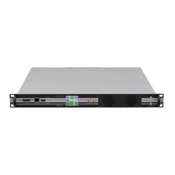
REBLE610 Fully indoor Microwave Link Figure 96: Web Log form – filters (selection of number of lines per page). 9 Panels. 9.1 Front Panel. Figure 97 : REBLE610 front panel. Item Description Function Connector DB15 Remote control. Connector RJ-45 Ethernet 10/100 port for Management. -
Page 52: Back Panel
In/out ASI J (software configuration). Connector BNC 75 Ohm In/out ASI K/E1 OUT (software configuration). Connector RJ-45 Link for 1+1 configuration with paired REBLE610 for space diversity, frequency diversity and hot-standby. Connector RJ-45 Baseband data transit between a receiving terminal and a transmitting terminal (software configuration).
Need help?
Do you have a question about the REBLE610 and is the answer not in the manual?
Questions and answers