Table of Contents
Advertisement
Advertisement
Table of Contents

Summary of Contents for Carel mRack
- Page 1 µRack Standard compressor racks single/two circuit...
- Page 3 We wish to save you time and money! We can assure you that the thorough reading of this manual will guarantee correct installation and safe use of the product described. IMPORTANT WARNINGS BEFORE INSTALLING OR HANDLING THE APPLIANCE PLEASE CAREFULLY READ AND FOLLOW THE INSTRUCTIONS DESCRIBED IN THIS MANUAL.
-
Page 5: Table Of Contents
CONTENTS Product ..............................................3 1.1. General functions ....................................3 1.2 Main characteristics .....................................3 User interface 2.1 Buttons - LEDs - Icons....................................5 2.2 LED display and Icons....................................6 Starting the unit .............................................6 3.1. Starting for the first time..................................6 3.2. Unit configuration ....................................6 3.2.1. Input configuration....................................7 3.2.2. - Page 6 Alarm management..........................................19 7.1. Alarms with automatic reset ................................19 7.2. Alarms with manual reset...................................19 7.3. Semiautomatic alarms ..................................20 7.4. Alarm relay ......................................20 The supervisor network ........................................21 7.5. Alarms from analogue inputs: temperature probe and pressure transducer:.................20 8.1. Serial boards ......................................21 8.2.
-
Page 7: Product
Possibility to modify the access level to the parameters from the keypad (only from MANUFACTURER level). Hardware • The product comes ready for panel installation, 32x74, and DIN rail mounting. Cod. CAREL +03P220431 rel. 0.0 del 08/09/05 - preliminary version... -
Page 8: User Interface
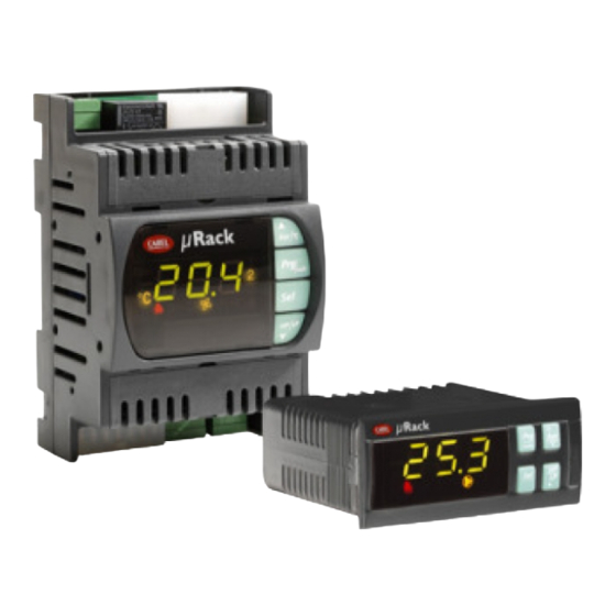
As well as displaying the values measured and the operating conditions of the unit, the user terminal (display and keypad) can be used to modify the unit operating parameters. The following figures show the µRack for panel installation and for DIN rail mounting. Cod. CAREL +03P220431 rel. 0.0 del 08/09/05 - preliminary version... -
Page 9: Buttons - Leds - Icons
Press the two buttons together, when the numeric value of one of the following parameters is displayed: comp/fan set point high/low threshold differentials to switch the display of the same parameter from BAR to °C. Cod. CAREL +03P220431 rel. 0.0 del 08/09/05 - preliminary version... -
Page 10: Led Display And Icons
After having checked the connections, power-up the unit. When started for the first time, the controller performs a LAMP TEST and uses the default values selected by CAREL for all the configuration parameters: Unit with 2 compressors + 2 fans + alarm relay. -
Page 11: Input Configuration
RATIOMETRIC pressure probe (0 to 5 Volt) Room temperature probe (display) / auxiliary probe CAREL NTC temperature probe (-50T100°C; R/T 10 kΩ at 25°C) Outside air temperature probe (floating condenser control) / CAREL NTC temperature probe (-50T100°C; R/T 10 kΩ at 25°C) -
Page 12: Wiring Diagrams
µRack Analogue outputs Outputs Description Fans speed controller (PWM) 3.3.2. Wiring diagrams: Panel installation: DIN rail installation: Cod. CAREL +03P220431 rel. 0.0 del 08/09/05 - preliminary version... -
Page 13: Compressor Management
Fig 4.1 Dead band This type of control features the definition of a dead band to the side of the set point, within which no device is started or stopped. Cod. CAREL +03P220431 rel. 0.0 del 08/09/05 - preliminary version... - Page 14 N.B. To make the device call time constant in the activation phase, simply set the times TOnMax and TonMin to the same value. The same is true for the deactivation phase. Cod. CAREL +03P220431 rel. 0.0 del 08/09/05 - preliminary version...
-
Page 15: Number Of Compressors Started With Probe 1 Fault
“r01” “r02” Differential “/03” Comp1 “/04” Comp2 “/05” Comp3 “/06” Maximum capacity Pressure Requirement kW Comp1 Comp2 Comp3 Total active capacity kW 1.35 10.8 13.5 14.85 18.9 20.25 Table 4.1 Cod. CAREL +03P220431 rel. 0.0 del 08/09/05 - preliminary version... -
Page 16: Manually Enable/Disable The Compressors
High pressure HP1 S2 (pressure) A (press – temp) S3 (temperature) B (only temp) Temperature 1 S3 (temperature) A (AUX probe) B (not used) Temperature 2 S4 (temperature) Always present Cod. CAREL +03P220431 rel. 0.0 del 08/09/05 - preliminary version... -
Page 17: Compressor Time Settings
This parameter limits the number of starts per hour. If, for example, the maximum allowable number of starts per hour is 10, to guarantee this limit simply set a value of 360 (parameter C05). Key: Compressor call Compressor T[s] TSameSw Minimum time between starts of the same compressor Time T[s] TSameSw Cod. CAREL +03P220431 rel. 0.0 del 08/09/05 - preliminary version... -
Page 18: Fan And Inverter Management
Rotation automatically excludes any fans with active alarms. A fan with an active alarm is automatically stopped, and another will immediately be called, so as to satisfy the load. Two different types of rotation can be set: Cod. CAREL +03P220431 rel. 0.0 del 08/09/05 - preliminary version... -
Page 19: Inverter Management
Proportional and integral control (PI) To minimise any deviations in stable operating conditions between the controlled value and the set point, typical of proportional control, a proportional plus integral strategy (P+I) can be sued. Cod. CAREL +03P220431 rel. 0.0 del 08/09/05 - preliminary version... - Page 20 HP set point T[s] Inverter DOnZ Activation zone DOffZ Deactivation zone 10 V Dead band T [s] Time Inverter Inverter status NFan Number of fans on T[s] NFan T[s] Fig. 5.6 Cod. CAREL +03P220431 rel. 0.0 del 08/09/05 - preliminary version...
-
Page 21: Pwm-Ppm Management
T[s] T[s] Fig. 5.7 The PWM signal controls, for example, the CAREL FCS* series, CONONOFF, CON0/10A0 modules. The PPM signal controls, for example, the CAREL MCHRT*** series modules. ON/OFF fan control board (code CONVONOFF0) The CONVONOFF0 modules convert the PWM signal sent from terminal Y to an ON/OFF signal. In practical terms, Y can be used to control a relay. Switching power 10A at 250 Vac in AC1 (1/3 HP inductive). -
Page 22: Various Settings
C06. If the discharge pressure falls below the Prevent threshold, any other compressor start calls are ignored, for a set time called Prevent time 1 (parameter A13). Cod. CAREL +03P220431 rel. 0.0 del 08/09/05 - preliminary version... -
Page 23: Alarm Management
If, in this situation, new alarms are activated, the initial situation will return.. If the causes no longer exist, the status of the signal devices changes as follows: • The alarm relay changes to normal status; • ALARM LED goes off.. Cod. CAREL +03P220431 rel. 0.0 del 08/09/05 - preliminary version... -
Page 24: Semiautomatic Alarms
1.0 bar discharge Diff. Example of LP alarm management Alarm on Alarm off Low press. Set Point Diff. Example of HP alarm management Alarm on High press. Set Point Alarm off Cod. CAREL +03P220431 rel. 0.0 del 08/09/05 - preliminary version... -
Page 25: The Supervisor Network
In addition, this function allows the possibility to modify a series of parameters from the supervisor, such as: set point, differentials, times, unit status, reset alarms etc. Also see the paragraph Supervisor communication variables. 8.1. Serial boards For connection to supervisory systems, the control uses the standard Carel RS485 serial protocol. Serial connection options: Product code RS485... - Page 26 Capacity comp 2 Capacity of compressor 2 0 to 500 different capacities are enabled Only if comp. with Capacity comp 3 Capacity of compressor 3 0 to 500 different capacities are enabled Cod. CAREL +03P220431 rel. 0.0 del 08/09/05 - preliminary version...
- Page 27 Probe calibration -12 to 12 B1 (discharge) : Discharge probe calibration Room probe calibration Probe B2 calibration °C -12 to 12 Probe B3 calibration Outside probe calibration °C -12 to 12 Cod. CAREL +03P220431 rel. 0.0 del 08/09/05 - preliminary version...
- Page 28 C02 Minimum off time for same compressor 0 to 999 time Min. time between Minimum time between two start call s for different compressors. starts of different 0 to 999 Avoids simultaneous starts compressors : Cod. CAREL +03P220431 rel. 0.0 del 08/09/05 - preliminary version...
- Page 29 0 to 20.0 proportional to the suction pressure time varies Min compressor set Set the lower limit of the compressor set point circuit 1 0 to r14 point Cod. CAREL +03P220431 rel. 0.0 del 08/09/05 - preliminary version...
- Page 30 7.0 bar LP suction 2 delay A08 Suction probe alarm: delay setting 0 to 999 -95T95 or HP discharge alarm A09 Discharge probe alarm: high threshold setting bar /°C 20.0 0T30 Cod. CAREL +03P220431 rel. 0.0 del 08/09/05 - preliminary version...
- Page 31 Enable operation of fan 3 in automatic mode: Enable fan 3 0) NO 0 / 1 1) YES Enable operation of fan 4 in automatic mode: Enable fan 4 0) NO 0 / 1 1) YES Cod. CAREL +03P220431 rel. 0.0 del 08/09/05 - preliminary version...
-
Page 32: On/Off Fan Control Board (Code Convonoff0)
The CONV0/10A0 modules convert the PWM signal sent from terminal Y on the µRack to a standard 0 to 10 Vdc (or 4 to 20 mA) signal. The FCS series three-phase controllers can be connected to the µRack without requiring this module. Cod. CAREL +03P220431 rel. 0.0 del 08/09/05 - preliminary version... -
Page 33: Programming Key (Code Psopzkeya0)
Warning: The parameters can only be copied only between instruments with the same product code. The upload operation, on the other hand, is always possible. To assist the identification of the key to be used, CAREL has applied a label that can used to describe the programming made or the unit that the data refers to. - Page 34 Alarm: low suction pressure 1 “A15” Alarm: high suction pressure 1 “A16” Alarm: low suction pressure 2 “A17” Alarm: high suction pressure 2 “A18” Probe B1 faulty or disconnected “A19” Cod. CAREL +03P220431 rel. 0.0 del 08/09/05 - preliminary version...
- Page 35 Type of compressor control “r06” Maximum call for compressor starts in dead band by time “r08” Maximum call for compressor stops in dead band by time “r10” Type of fan rotation “r20” Cod. CAREL +03P220431 rel. 0.0 del 08/09/05 - preliminary version...
-
Page 36: Default Configurations
Glossary Analogue value: integer value with minus sign and decimal point. Buffer (memory): memory on the board used to save the default values selected by CAREL for all the parameters. Permanent memory, saves the values even when power is disconnected. - Page 37 µRack Cod. CAREL +03P220431 rel. 0.0 del 08/09/05 - preliminary version...
- Page 38 µRack CAREL SpA reserves the right to make modifications or changes to its products without prior notice. Cod. CAREL +03P220431 rel. 0.0 del 08/09/05 - preliminary version...
- Page 40 Agency: CAREL S.p.A. Via dell’Industria, 11 - 35020 Brugine - Padova (Italy) Tel. (+39) 049.9716611 - Fax (+39) 049.9716600 http://www.carel.com - e-mail: carel@carel.com...
Need help?
Do you have a question about the mRack and is the answer not in the manual?
Questions and answers