Table of Contents
Advertisement
Advertisement
Table of Contents
Troubleshooting

Summary of Contents for MEDA MD-6000P
- Page 1 MD-6000P Bladder Scanner USER MANUAL MEDA Co., Ltd www.meda.com.cn...
- Page 2 MEDA Co., Ltd. F2C, F3D, F4C, F5, F6C, Building C2, Xinmao Science Skill Park, Huayuan Industry Development Area, Tianjin 300384, PEOPLE’S REPUBLIC OF CHINA Tel: +86-22-83713808 Fax: +86-22-83713880 URL: http://www.meda.com.cn E-mail: export@meda.com.cn Shanghai International Holding Corp. GmbH (Europe) Eiffestrasse 80, 20537 Hamburg, GERMANY...
-
Page 3: Table Of Contents
CONTENTS CONTENTS FCC STATEMENT ............................. IV PRECAUTIONS AND WARNINGS ........................V LABELS AND INDICATORS .......................... VII EXPLANATION OF LABELS AND SYMBOLS ON THE PACKING BOX ..........VIII CHAPTER 1 INTRODUCTION ........................1 1.1 G ..........................1 ENERAL ESCRIPTION 1.2 M ............................ - Page 4 CONTENTS 4.3.1 Start-up and Shut-down of the Tablet PC ..................... 23 4.3.1.1 Check-up before Start-up ........................23 4.3.1.2 Start-up ............................23 4.3.1.3 Check-up before use ........................23 4.3.1.4 Shut-down of the Tablet PC ......................23 4.3.2 Configuration of the Tablet PC and Software Installation Instructions ..........23 4.3.3 Main Interface ............................
- Page 5 CONTENTS 6.6 D ..................... 46 ISPOSAL OF EVICE AFTER ITS YCLE CHAPTER 7 SERVICE AND SUPPORT INFORMATION ................ 47 7.1 W ..............................47 ARRANTY 7.2 A ......................47 CCESSORIES AND ONSUMABLES 7.2.1 Accessory ............................47 7.2.2 Optional Accessory ........................... 47 7.2.3 Consumable ............................
-
Page 6: Fcc Statement
The device has been evaluated to meet general RF exposure requirement. The device can be used in portable exposure condition without restriction. Changes or modifications made to this equipment not expressly approved by MEDA may void the FCC authorization to operate this equipment. -
Page 7: Precautions And Warnings
Portable RF communications equipment (including peripherals such as antenna cables and external antennas) should be used no closer than 30 cm (12 inches) to any part of MD-6000P. Otherwise, degradation of the performance of MD-6000P could result. ... - Page 8 PRECAUTIONS AND WARNINGS When the battery is charged with AC power, it is prohibited to connect other devices onto the same AC power socket. Although the device complies with the requirements of electromagnetic immunity in IEC 60601-1-2, it should be kept away from strong interference sources, such as high-frequency electric knife, magnetic resonance imaging equipment, microwave therapy instruments and other RF treatment equipment.
-
Page 9: Labels And Indicators
Labels and Indicators Labels and Indicators Serial Number "Type BF" Applied Part CAUTION! Important information that operator must read carefully. Please Refer to User Manual Manufacturer Logo of Manufacturer “ON” or “OFF” Charger Interface CE Conformity Marking Authorized Representative in the European Community The battery meets RoHS requirements. -
Page 10: Explanation Of Labels And Symbols On The Packing Box
Labels and Indicators Explanation of Labels and Symbols on the Packing Box This Way Up Fragile, Handle with Care Keep Dry Stacking Limit by 4 Temperature Limit Humidity limitation - VIII -... -
Page 11: Chapter 1 Introduction
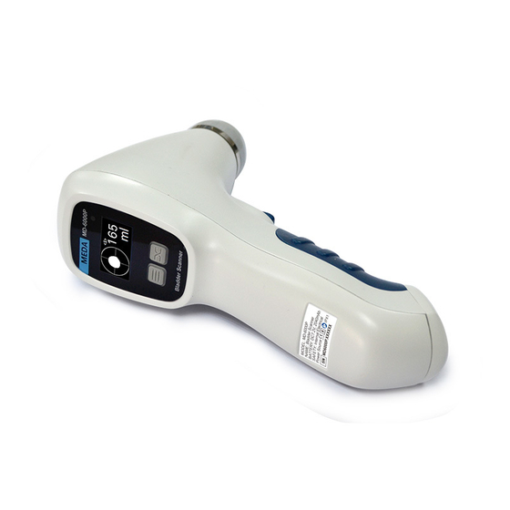
Chapter 1 Introduction 1.1 General Description MD-6000P Bladder Scanner (hereinafter referred to as “the device”) is a hand-held device which utilizes ultrasonic distance measuring principle to calculate urine volume in the bladder. It integrates a 2.5MHz B-mode 3D mechanical sector scan probe, a 1.3-inch OLED screen and a Li-ion battery, and comes with a charger. -
Page 12: Chapter 2 Specifications
Chapter 2 Specifications Chapter 2 Specifications 2.1 Working Conditions 5 ℃~40 ℃ Ambient temperature: ≤80% Relative Humidity: Atmospheric Pressure: 70-106kPa Power Supply: —Main Unit (internal power supply): rating voltage: DC7.2V; 2,040mAh rechargeable Li-ion battery. —AC/DC Adaptor (Charger): AC 100~240V, 50/60Hz, 0.5A max. 2.2 Specifications ... -
Page 13: Product Classification
Chapter 2 Specifications Note: The detachable parts, such as the charger, should be packed into the original package before transportation. 2.5 Product Classification According to the type of protection against electric shock: Internally powered (working); Class II (charging) According to the degree of protection against electric shock: Type-BF Applied Part According to the degree of protection against harmful ingress of water or particulate matter: The Main Unit: IPX1 The Probe Cover: IPX7 (See Fig. -
Page 14: Chapter 3 Installation
Chapter 3 Installation Chapter 3 Installation 3.1 Structure MD-6000P Bladder Scanner is a hand-held device consisting of Main Unit and Charger, which can be used together with Tablet PC. ⑥ ③ ① ① OLED Screen ② ④ ② Menu Key ⑦... - Page 15 Chapter 3 Installation a) Main Unit OLED Screen For displaying interface information. Menu Key The Menu Key is mainly used for screen switching. Please refer to §4 Operation for details. Power Indicator The power indicator lights up when the device is turned on. The power indicator goes out when the device is turned off.
-
Page 16: Environmental Requirement
Chapter 3 Installation ① Notes: Please connect the device to the mains power only when it is off. ② The device shall not be positioned where it’s difficult to disconnect while charging. Charging Indicator The charging indicator lights up in red during charging. The charging indicator lights up in green when the battery is fully charged. -
Page 17: Using Together With Tablet Pc
Chapter 3 Installation 3.3.2 Using Together with Tablet PC The tablet PC can be used as a supporting accessory. It uses an Android operating system with a bladder scan App. It can be used together with the Main Unit. 3.3.2.1 Structure of the Tablet PC There is no electrical connection between the tablet PC and the Main Unit. - Page 18 Chapter 3 Installation Screen The display area of the Tablet PC and user interaction area. The screen presents information to users and users can click the screen to enter the information. Micro USB Port This port can be used for charging and data transmission. Tablet PC charging: plug the Tablet PC charger plug into the port, it can be charged.
-
Page 19: Chapter 4 Operation
Chapter 4 Operation Chapter 4 Operation 4.1 Start-up and Shut-down 4.1.1 Check-up before Start-up Environment Check whether there is nearby equipment that may emit disturbing radiation. Appearance Check whether there are cracks on the enclosure of the device and the OLED screen. Check whether the device has leakage, deformation, smell, discoloring and so on. -
Page 20: Introduction Of The Function Module
Chapter 4 Operation 4.2 Introduction of the Function Module 4.2.1 Main Interface Press the power switch button to start up the Main Unit. The screen displays patient information (if it is used together with the Tablet PC), battery power and volume value, and the initial value of the volume is 0 ml, as shown in Fig. -
Page 21: System Parameter Setting
Chapter 4 Operation battery in time when idle, so as to avoid the excessive consumption of the battery due to continuous usage which will affect its service life. Fig. 4.2a Full Battery Capacity Fig. 4.2b Empty Battery Capacity Note: When the battery power is used up, you can still save the current data. The device will shut down automatically after three buzzes. - Page 22 Chapter 4 Operation Under the Operator List Interface, press the Function key and switch through the list to select the operator. If an operator is selected, press the Scan button to save automatically and “*” is displayed on the left of the selected operator. 4.2.2.2 Test Mode Test Mode is used for the measurement on a bladder scanner phantom.
- Page 23 Chapter 4 Operation 4.2.2.4 Automatic Shutdown Press the Menu key continuously under the System Setting interface until you switch to the Automatic Shutdown interface, as shown in Fig. 4.6. POWER: Shutdown 10 min Fig. 4.6 Automatic Shutdown Interface The Automatic Shutdown Interface displays shutdown time, which is divided into 5 options that are 5 min, 10min, 15min, 20min and Never (deactivating automatic shutdown).
- Page 24 Chapter 4 Operation After the setting is completed, if there is no operation in the set time period, the system will shut down the screen automatically, thereby improving the battery life of the system. Press any key of the Main Unit to wake up the screen. 4.2.2.6 Sound Setting Press the Menu key continuously under the System Setting interface until you switch to the Sound Control interface, as shown in Fig.
-
Page 25: Patient Selection
Chapter 4 Operation VERSION: V 1.0 Fig. 4.10 Version Information Interface 4.2.3 Patient Selection a) When the group number is “New”, it is the New Patient mode (or press the Function key to switch to the New Patient mode). Under this mode, the sex of patient can be selected. Press the Menu key of the Main Unit to switch to SEX interface as shown in Fig. -
Page 26: Scanning
Chapter 4 Operation 4.2.4 Scanning 4.2.4.1 Bladder Positioning Fig. 4.13 Patient Position Correct positioning of the bladder is the basis for accurate measurement of bladder volume. As shown in Fig. 4.14, the bladder is located in the lower abdomen of the human body above the joint of phalanxes. - Page 27 Chapter 4 Operation (a) Top View (b) Side View Fig. 4.14 Position of the Main Unit Ultrasonic coupling gel should be applied to the lower abdomen of the patient before measurement and the Main Unit should be placed as shown in Fig. 4.14a and Fig. 4.14b. Note that the top of the Main Unit is directed towards the patient's head and the handle is directed towards the patient's feet.
- Page 28 Chapter 4 Operation Fig. 4.15 Pre-scan Positioning Mode The vertical line on the screen is the center line, and the area surrounded by the oblique lines on both sides of the center line represents the scanning area; the circle on the screen represents the bladder, the center of the circle is the center of the bladder, as shown in Fig.
- Page 29 Chapter 4 Operation Fig. 4.17a Incorrect position, Fig. 4.17b Incorrect position, move the Main Unit to the left. move the Main Unit to the right. The continuous pressing of the Scan button shall be within 5 minutes to avoid overheating of the Main Unit. 4.2.4.3 3D Scanning Mode The 3D Scanning Mode refers to the process that the Main Unit makes three-dimensional scanning with an interval of 15°...
- Page 30 Otherwise it may result in inaccuracy of the measurement results. ② When the level of electromagnetic disturbance to which the MD-6000P is subjected exceeds its immunity (see Annex C), if the interference to the B-mode image affects the correct identification of the bladder boundary, it may increase the measurement error of urine volume in the bladder.
- Page 31 Chapter 4 Operation When the bladder projections are like what is shown in Fig. 4.19a, b, c and d, please adjust the position and angle of the Main Unit and re-measure. Fig. 4.19a Incorrect Position Fig. 4.19a: The bladder projection is beyond the center of the testing area. It is under the center of the testing area, the measurement result is inaccurate.
-
Page 32: Recommended Operation Procedure
Chapter 4 Operation the center of the testing area, the measurement result is inaccurate. Adjust the angle and position of the Main Unit to the right side of the patent and re-measure it. Fig. 4.19d: Incorrect Position Fig. 4.19d: The bladder projection is beyond the center of the testing area. It is on the right of the center of the testing area, the measurement result is inaccurate. -
Page 33: Operation Instructions For The Jointly-Used Tablet Pc
Chapter 4 Operation prompt scanning and the bladder volume will be displayed. 6. Press the Menu key to view the projection image, and select the appropriate position and angle of the Main Unit according to the projection position. 7. Usually, make 3 to 5 measurements for the same patient and select a more accurate measurement result. -
Page 34: Main Interface
Chapter 4 Operation WLAN: 2.4GHz, conforms to 802.11 b/g/n. 4.3.2.2 Software Installation Instructions Insert the flash drive, which is provided with the device and supports the OTG function, into the Micro USB port of the Tablet PC, open the file manager, select the installation package “Medascan.apk”... - Page 35 Chapter 4 Operation ③ System Setting The icon of entering system parameter setting displays in this area. Click it to enter system parameter settings See §4.2.2 System Parameter Setting for details. ④ Scanning Section Mark When a patient's measurement is completed, this area shows the mark of the scanning section of the Main Unit, which corresponds to the ultrasound image one by one, as shown in Fig.
- Page 36 Chapter 4 Operation ⑥ Ultrasound Image Display When a patient's measurement is completed, the area displays the ultrasound image of the patient's bladder, the bladder cross-sectional area measurements and the image number. A total of 12 bladder ultrasound images can be displayed and viewed by clicking the Sliding Page Turning key.
-
Page 37: Main Unit Connection
Chapter 4 Operation Report key Click the key to integrate images, data and add diagnostic information, REPORT and then generate case report. See §4.3.10 Case Report for details. Wi-Fi key Press the key to connect it to the paired Main Unit. See §4.3.4 Main Unit Connection for details. -
Page 38: Patient Information Interface
Chapter 4 Operation Fig. 4. 23a Connected Fig. 4.23b Unconnected Fig. 4.24 Successful Connection 4.3.5 Patient Information Interface Click the NEW key in the Main Interface to enter the Patient Information Interface, as shown in Fig. 4.25. You can input the patient ID, name, age and sex here. Fig. - Page 39 Chapter 4 Operation Case ID input Click the input box to input patient’s ID through the soft numeral keypad popping up from the bottom of the interface. Age input box Click the input box to input patient’s age through the soft numeral keypad popping up from the bottom of the interface.
-
Page 40: Scanning Mode
Chapter 4 Operation Click the NEW key on the Tablet PC to create a new patient, and click the OK key will send patient’s information to the Main Unit, at the same time the Main Unit switches to the <New> mode. Then, start scanning and the result of scan will be displayed on the Tablet PC;... -
Page 41: Save
Chapter 4 Operation adjust the position of the Main Unit and measure again. The bladder projection image is consistent § with the bladder projection of the Main Unit, see 4.2.4.4 Bladder Projection Image for details. 4.3.9 Save After measurement on a patient, click the SAVE key in the Main Interface to save the case record. At this point, the progress bar popping up on the Main Interface prompts "Please Wait While Saving ...", when the words of the progress bar disappear, the record is successfully saved, meanwhile, the patient’s case information is saved to the patient medical record database. -
Page 42: Patient Case Management
Chapter 4 Operation Click the printer icon button on the upper right corner to print the report. Report printing supports wireless printer and USB interface printer. Click the save icon button on the upper right corner to save the report. Note that if there is no printer driver, you need to install the driver. -
Page 43: System Parameter Setting
Chapter 4 Operation Click the key to search for patient medical record according Search key to the patient’s name. (Search) Click the key, the user can select to search according the Search key key words included in Name, ID, Sex, Age, Vol (Volume), (Conditional Date, Time and Operator. -
Page 44: Name Of Medical Institution
Chapter 4 Operation Fig. 4.31 System Parameter Setting 4.3.13 Name of Medical Institution Click the edit box under “Hospital” to input the name of the medical institution with the soft keypad popped up. 4.3.14 Operator List Click the item of “Operator” to enter the Operator List Interface, as shown in Fig. 4.32. When you enter the interface, the software automatically reads the operator list stored in the Main Unit to the Tablet PC and displays name with a tick. -
Page 45: Patient List
Chapter 4 Operation Fig. 4.32 Operator List Add key Click the key to pop up a dialogue box and prompt to enter the operator’s name and add a new operator to the Operator list. Delete key Select the operator to be deleted and click the key to delete DELETE the operator in the Operator List. - Page 46 Chapter 4 Operation Fig. 4.33 Patient List Add key Click the key to pop up a dialogue box and prompt to enter the patient’s ID, name, age and sex, to add a new patient to the patient list. Delete key Select the patient to be deleted and click the key to delete DELETE the patient in the patient list.
-
Page 47: Pair Key
Chapter 4 Operation 4.3.16 Pair Key Click the key in the Main Interface to enter the settings interface where you can see the Pair key. The display of UnPair indicates the Main Unit has been paired and Pair indicates not paired. ①... -
Page 48: Preset Case List Mode
Chapter 4 Operation 4.4 Preset Case List Mode The mode is suitable for patients with relatively fixed locations, such as nursing homes, fixed bed inpatient departments and other scenes in which the patient information is known. It needs to configure the patient case list in advance for scan. 4.4.1 Patient List Preset The configuration of Patient List to be tested should be operated in the Tablet PC and uploaded to the Main Unit. -
Page 49: Chapter 5 Cleaning And Disinfection
Chapter 6. Maintenance and Trouble Shooting Chapter 5 Cleaning and Disinfection 5.1 Cleaning of Main Unit ® Use soft cloth with mild detergent (e.g. diluted Bianex Special Efficiency Multi-Enzymatic Cleanser) or water to clean the surface of Main Unit. For further disinfection, use soft cloth with prepared disinfectant solution (Sporicidin Sterilizing and Disinfecting Solution) to wipe the surface of the Main Unit. -
Page 50: Clean-Up
Chapter 6. Maintenance and Trouble Shooting See Fig. 5.1, the part under the metal ring is at an IPX7 level; the part above the metal ring is at an IPX1 level. Note: Do not put the part above the metal ring into liquid. 5.2.2 Clean-Up The probe cover should be kept clean. -
Page 51: Chapter 6 Maintenance And Troubleshooting
Chapter 6. Maintenance and Trouble Shooting Chapter 6 Maintenance and Troubleshooting 6.1 Maintenance and Attentions The device should be operated in a clean, well-ventilated environment without corrosive gases or electromagnetic interference. Do not use or store the device where the humidity and temperature go beyond regulated standards;... -
Page 52: Recommended Use
Chapter 6. Maintenance and Trouble Shooting cause the battery overheating, overflow, fire and other hazards. The manufacturer shall not be liable for any accidents caused by disobeying these instructions and attentions. 6.2.1 Recommended Use Please use the device under normal indoor environment. The device should be used away from heat sources. -
Page 53: Warnings
Portable RF communications equipment (including peripherals such as antenna cables and external antennas) should be used no closer than 30 cm (12 inches) to any part of MD-6000P. Otherwise, degradation of the performance of the device could result. -
Page 54: Cautions
Chapter 6. Maintenance and Trouble Shooting When the level of electromagnetic disturbance to which the MD-6000P is subjected exceeds its immunity (see Annex C), if the interference to the B-mode image affects the correct identification of the bladder boundary, it may increase the measurement error of urine volume in the bladder. -
Page 55: Maintenance Of Screen
Chapter 6. Maintenance and Trouble Shooting Note: Plastic bags are dangerous, please put them away from infants and children to avoid the risk of suffocation. The part above the metal ring on the housing of the Main Unit shall not be dipped into water or other liquids. -
Page 56: Disposal Of Device After Its Life-Cycle
Chapter 6. Maintenance and Trouble Shooting 6.6 Disposal of Device after its Life-Cycle Disposal of the device after its life-cycle shall comply with the relevant local environment protection regulations. The same way with the electronic devices (computers, etc) can be taken. - 46 -... -
Page 57: Chapter 7 Service And Support Information
Chapter 7. Service and Support information Chapter 7 Service and Support Information 7.1 Warranty The product has a warranty of one year from the purchasing date on the premise of using in accordance with the User Manual. If the device does not work properly, please contact your local distributor or the manufacturer immediately. -
Page 58: Consumable
Chapter 7. Service and Support information 7.2.3 Consumable Item Model Specification —— Acoustic Gel With local approval for marketing. ① Notes: The Main Unit Charger used with the device must be provided by the manufacturer. Using accessories other than those provided by the manufacturer may cause increased electromagnetic emissions or decreased electromagnetic immunity of the device and result in abnormal operation. -
Page 59: Annex A. Conservation Concept Declaration
Annex A. Conservation Concept Declaration Annex A. Conservation Concept Declaration A.1 Declaration The biological effect of ultrasound may be evidenced in future, albeit no evidence on this currently exists. Although MD-6000 itself produces ultrasound of low level, we have to bear the concept of using lowest level of ultrasound that could bring clinic data needed, and use the shortest time as reasonably as possible. -
Page 60: Annex B. Acoustic Output Reporting Table
Annex B. Acoustic Output Reporting Table Annex B. Acoustic Output Reporting Table According to IEC 60601-2-37 System Model: RZ17060020 Transducer Model: Operating Mode: MD-6000P Index Label Below Below surface surface surface surface Maximum Index Value 0.148 0.00052 0.00106 0.00106 Index Component Value 0.00052... -
Page 61: Annex C. Guidance And Manufacturer's Declaration
Guidance and manufacturer’s declaration - electromagnetic immunity The MD-6000P BLADDER SCANNER is intended for use in the electromagnetic environment specified below. The customer or the user of the MD-6000P BLADDER SCANNER should assure that it is used in such an environment. -
Page 62: Annex D. Main Specification Of Wireless Wi-Fi
Annex D. Main Specification of Wireless Wi-Fi Annex D. Main Specification of Wireless Wi-Fi Frequency Range 2,412-2,462 MHz RF Output Power (EIRP) 13.50 dBm Modulation DSSS, OFDM Mode of Operation (Simplex / Duplex) Duplex - 52 -... -
Page 63: Annex E. References
Annex E. References Annex E. References Mclean GK,Edell SL.Determination of boadder volumes by gray scale ultrasonography.Radiology,1978,128:181-182. Mark LS,Dorey FJ,Macairan ML,et al.There dimensional ultrasound device for rapid determination of bladder volume.Urology,1997,50(3):341-348 Coombes GM,Millard RJ.The accuracy of portable ultrasound acanning in the measurement of residual urine volume[J].The Journal of Urology,1994,152:2083-2085 Coombes, Graham., Millard, Richard J.,(1994) The Accuracy of Portable Ultrasound In The Measurement Of Residual Urine Volume .
Need help?
Do you have a question about the MD-6000P and is the answer not in the manual?
Questions and answers