
Summary of Contents for Hypex Electronics DLCP
- Page 1 Hypex Electronics BV Kattegat 8 9723 JP Groningen, The Netherlands +31 50 526 4993 sales@hypex.nl www.hypex.nl User Manual R3 Digital Loudspeaker Cross-over Platform (DLCP)
-
Page 2: Table Of Contents
Product overview ............................ 13 DLCP setups ........................... 13 3.1.1 Example 1: DLCP as preamplifier ..................13 3.1.2 Example 2: DLCP as active loudspeaker filter ..............14 Application notes ........................... 15 Hypex Filter Design ..........................16 Target response ..........................16 Driver correction ..........................16 Crossover design ........................... -
Page 3: Product Description
Static electricity can cause damage to this product. The first time the DLCP is used all biquads are zero, so there are no filters installed. Connecting any speakers and audio input at this point may cause some damage to them. -
Page 4: Applications
DLCP User manual R3 96kHz sampling rate Can be used as a digital pre amplifier Stand-by mode On board Molex® Microfit® output connectors Connector for external Led. Optional control board with IR receiver for IR control, LCD display and buttons... -
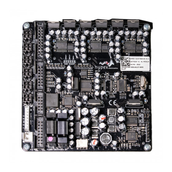
Page 5: Connections
Analogue audio output header (contains all audio outputs from J10-J15) Analogue/Digital audio in and digital output header I/O connector (USB, Relay, Control) DLCP SMPS power supply connector (Do not use when a Hypex SMPS module auxiliary output is connected with J16) Gain adjust header analogue left input... -
Page 6: System Information
The module has six Molex® Microfit® audio outputs, which can be used to connect NC400 / buffered UcD™ ST and HG modules. The supply can be provided by the new DLCP SMPS or the auxilia- ry output of a Hypex Switched Mode Power Supply module. The DLCP can go into standby mode and shut down the power supply, when an external standby voltage is applied and a controlboard is pre- sent. -
Page 7: Recommended Operating Conditions
A microcontroller controls the DSP and other ICs and I/O’s on the PCB, communicates with the con- trol board, PC and/or other DLCP’s that may be attached. When the module is powered on it will au- tomatically start up with the last settings. All settings, like volume and source selection, are stored after a change is made. -
Page 8: Add-Ons
It’s possible to connect two DLCP’s with only one input board. J5/J5B can be used to connect the third DLCP, or the second DLCP if it’s not in the same case. The control and digital outputs of the first DLCP (connected to J2/J3) and analogue inputs are linked trough the inputs of the second DLCP (connected to J2B/J3B). - Page 9 DLCP User manual R3 Analogue/Digital audio in and digital output header for optional second DLCP I/O connector (USB, Relay, Control) I/O connector (USB, Relay, Control) for optional second DLCP AES in select (J8 or J4) AES out select (from DLCP1, J2 / DLCP2, J2B)
- Page 10 XLR input, and other position to use the AES input from the control cable. Set the switch in the position in Figure 6 if one DLCP is connected, and other position if there is an- other DLCP connected to J2B/J3B.
-
Page 11: Dlcp Control Board
This controller board contains a LCD display which shows the settings and contains an IR receiver for an IR remote controller. The IR remote (not included) can control volume, mute, input and power. When 2 or more DLCP modules are used, only one control panel is needed. 2.5.2.1 Connections... - Page 12 If the input is set to USB audio, then the input of the other DLCP’s in the chain can be chosen in the DLCP x set- up menu. The source for the other DLCP’s in the chain can be set to...
-
Page 13: Product Overview
Figure 13 The DLCP can be connected to the input board with two flat cables. J2 on the input board must be connected to J2 on the DLCP (Analogue / Digital Input). J3 on the input board must be connected to J3 on the DLCP (I/O). -
Page 14: Example 2: Dlcp As Active Loudspeaker Filter
3.1.2 Example 2: DLCP as active loudspeaker filter It’s possible to use the DLCP as an active filter so you can build an active speaker. It’s possible to work without the Hypex DLCP input board to keep it as small as possible. Then you will have to make your own adapters. -
Page 15: Application Notes
User manual R3 3.2 Application notes The DLCP has to be placed in an enclosure with enough airflow. Please mount the DLCP with spacers on a solid surface. All four mounting holes are connected to ground with a 100nF capacitor. Connect them all to chassis with a metal spacer for optimum EMI performance. -
Page 16: Hypex Filter Design
DLCP User manual R3 4 Hypex Filter Design After setting the right hardware settings, you’ll have to configure the software side. This is done by pc software, called Hypex DSP filter design. Please do not connect any speakers to your system yet! 4.1 Target response... -
Page 17: Control Panel
“enter”. All of the configurations made here will be redirected from the current module to any other connected DLCP’s, when a control board is present. So there is no need to connect the slave module to the pc to change these settings. -
Page 18: Filter Design
DLCP User manual R3 4.6 Filter design When you want to make some filters for your module they can be designed in the “Filter design”. Under view there can be switched between the control panel and the filter design window. The following pages will give you a widespread instruction of the possibilities of the program. -
Page 19: Graph Area
DLCP User manual R3 4.6.1 Graph Area The magnitude tab shows the imported driver responses, filters, individual biquads, individual fil- tered driver responses and the sum. Colour Function Pink, thin Measured Ch6 response Grey, thin Measured Ch5 response Brown, thin... -
Page 20: Settings Window
DLCP User manual R3 4.6.3 Settings window Figure 19 The settings window is under Tools > Options > Settings Measurement sampling rate sets the sample rate used in the imported response files (typically 48kHz). Processor sampling rate is that of the Hypex DSP hardware. Note that this setting does not control the sampling rate of the hardware. -
Page 21: Dlcp Options Window
The DLCP options window is under Tools > Options > DLCP options Two different IR remote codes can be used to control the DLCP control, this can be switched in the remote selection. This information will be send to the DLCP control when present. - Page 22 DLCP User manual R3 Figure 22 The first echo is apparent at 5ms. Zoom in until you see only the anechoic portion of the impulse response. Dragging the mouse, left-button down, from left to right marks a zoom area. Dragging from right to left zooms out.
-
Page 23: Designing Filters
DLCP User manual R3 The steps of loading and truncating data can be repeated at any time. This can be particularly prac- tical when combining close-up and far-field measurements during the filter design phase. The win- dow in Figure 23 shows the result of this. The small knot of corrections made around 70Hz is based on close-up data first loaded separately. -
Page 24: Firmware Update
DLCP firmware file. This is a complete hex file provided by Hypex, no adapts can and may be made by the user! After you selected the file the DLCP will enter its bootloader, the device will reconnect and shows version 99.99 in the status bar. Now you need to select the file again to load the new firmware into the module. -
Page 25: Filter Example
DLCP User manual R3 4.8 Filter example Example design using an existing M-T-M two-way cabinet. 4.8.1 The substrate The pre-existing cabinet used here is not an example of good acoustic design. A 1” dome tweeter is placed between two 5¼” woofers in perfect lateral and vertical symmetry. The measured responses... -
Page 26: Result
DLCP User manual R3 4.8.3 Result Amplitude response In blue the effective DSP crossover curves. In red the individual driver responses with these filters applied. Black shows the sum response. The measurement is valid down to just below 200Hz. Figure 25 The strategic placement of in total just 32 poles and 32 zeros corrects the response of this seeming- ly hopeless loudspeaker to within +/-1dB or +/-0.3dB (3rdoctave smoothing). - Page 27 DLCP User manual R3 Phase response The phase response obtained is shown below. At this stage, optimisation was stopped but further corrections could provide minimum phase up to the 20kHz with just a few extra zeros. Figure 27 Subjective evaluation Comparative listening tests on the test system show exactly the strengths and weaknesses that were expected based on the acoustic set-up.
-
Page 28: Dimensions
DLCP User manual R3 5 Dimensions 5.1 DLCP Top view Side view - 28 -... -
Page 29: Dlcp Input Board
User manual R3 DLCP 5.2 DLCP input board Top view Please download the 2D/3D files from our website 5.3 DLCP control board Front view NOTE: RJ45 connector not on picture Please download the 2D/3D files from our website - 29 -... -
Page 30: Revision History
LIFE SUPPORT POLICY: Use of Hypex products in life support equipment or equipment whose failure can reasonably be expected to result in injury or death is not permitted except by explicit written consent from Hypex Electronics BV. Warranty The work carries warranty out for all provable material and production defects for the duration of 12 months starting from sales.
Need help?
Do you have a question about the DLCP and is the answer not in the manual?
Questions and answers