Table of Contents
Advertisement
Available languages
Available languages
Quick Links
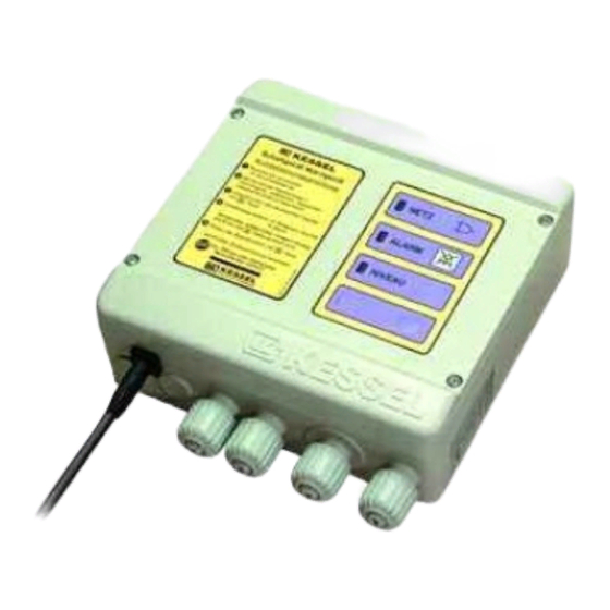
Warngerät mit Elektrodensonde (20 220) oder optischer Sonde (20 221)
Abbildung zeigt Art.Nr. 20 220
Installation
Inbetriebnahme
der Anlage wurde durchgeführt von Ihrem Fachbetrieb:
Name/ Unterschrift
Datum
ANLEITUNG FÜR EINBAU, BEDIENUNG UND WARTUNG
Einweisung
Ort
Produktvorteile
Schaltgerät Spritzwassergeschützt IP 54
Kombinierbar mit allen KESSEL-Tauchpumpen
Einsatz für leitende und nicht leitende Flüssigkeiten mit optischer Sonde
Einsatz für leitende Flüssigkeiten mit Elektrodensonde
Einfachste Montage (inkl. Montageset)
Stempel Fachbetrieb
D
GB Page 19
I
F
NL Pag. 73
PL Strona 91
Änderungsstand: 2016/10
Sachnummer:
243-005
Techn. Änderungen vorbehalten
Seite 1
Pagina 36
Page 54
Advertisement
Chapters
Table of Contents

Summary of Contents for Kessel 20220
- Page 1 NL Pag. 73 PL Strona 91 Produktvorteile Schaltgerät Spritzwassergeschützt IP 54 Kombinierbar mit allen KESSEL-Tauchpumpen Einsatz für leitende und nicht leitende Flüssigkeiten mit optischer Sonde Einsatz für leitende Flüssigkeiten mit Elektrodensonde Einfachste Montage (inkl. Montageset) Abbildung zeigt Art.Nr. 20 220...
-
Page 2: Table Of Contents
Inhaltsverzeichnis 1. Sicherheitshinweise ......................Seite 2. Allgemein ......................Seite 3. Montage / Elektroanschluß Montage des Warngerätes ..........Seite Montage der Sonden ............Seite Externer Signalgeber ............Seite Potentialfreier Kontakt ............Seite Kürzen der Steuerleitungen ..........Seite Installation / Kabelanschluss ..........Seite 4. - Page 3 1. Sicherheitshinweise Das Personal für Montage, Bedienung, DIN- und VDE-Normen und Richtlinien so - Es ist sicherzustellen, daß sich die Elektro- Wartung, und Reparatur muß die entspre- wie die Vorschriften der örtlichen Energie kabel sowie alle anderen elektrischen Anla- chende Qualifikation für diese Arbeiten auf- Ver sorgungs Unternehmen zu beachten.
- Page 4 2. Allgemein Sehr geehrter Kunde, wir freuen uns, daß Sie sich für ein Produkt von KESSEL entschieden haben. Die gesamte Anlage wurde vor Verlassen des Werkes einer strengen Qualitätskontrolle unterzogen. Prüfen Sie bitte dennoch so fort, ob die Anlage vollständig und unbeschädigt bei Ihnen angeliefert wurde. Im Falle eines Transportschadens beachten Sie bitte die Anweisung in Kapitel „Gewährleistung“...
- Page 5 3. Montage / Elektroanschluss 3.1 Montage Warngerät Die Sicherheitshinweise im Kapitel 1 sind zu beachten! Das Schaltgerät wird an geeigneter Stelle, z.B. in Augenhöhe an der Wand montiert. Später mit max. 1 Nm wieder verschrauben (selbstschneidende Schrauben). Den Schalt- kasten wie abgebildet mit den 4 Holzschrau- ben M3,5x30 an der Wand befestigen.
-
Page 6: Montage Der Sonden
3. Montage / Elektroanschluss 3.2 Montage der Sonden 3.3 Externer Signalgeber Die Sonde kann durch Kleben oder Andü- Der externe Signalgeber (Best.Nr. 20162) beln an den gewünschten Positionen ange- zur Übertragung des Warntons in andere bracht werden. Räume kann nach Bedarf angeschlossen werden. -
Page 7: Installation / Kabelanschluss
3. Montage / Elektroanschluss 3.6 Installation / Kabelanschluss Die Anschlussleitungen sind gemäß An- schlussplan anzuschlie ssen. Dazu zunächst in den Kabelverschrau bun gen die Dichtung mit ei nem Schraubenzieher durchstoßen (Bild a), die Leitung einführen (Bild b) und anklem- men (Bild c). An schlie ßend kann die Mutter der Kabelverschraubung mit der Hand fest- gezogen werden (Bild d). - Page 8 3. Montage / Elektroanschluss Abb. zeigt 20221 Abb. zeigt 20220 Gehäuse Schaltgerät rote LED „Alarm“ Anschluss Leitwertsonde oder optische Sonde PT-Schraube max. 1 Nm orange LED „Niveau“ Anschluss externer Signalgeber Netzanschlussleitung Taste „Alarm“ Leitwertsonde (20220) Kurzbedienungsanleitung Anschluss Potentialfreier Kontakt oder optische Sonde (20221) (Option;...
-
Page 9: Anschlussplan
4. Warngerät 4.2 Inbetriebnahme 4.1 Anschlussplan Beachten Sie bitte die Sicherheitshinweise in Kapitel 1. Sind alle elektrischen und mechanischen Komponenten, auch die Batterien, richtig angeschlossen, kann die Inbetriebnahme erfolgen: • Den Netzstecker in die Schutzkontakt- steckdose einstecken. • Es erfolgt ein Lauflicht der LED’s von oben nach unten. -
Page 10: Betrieb
Elektrosonde (nur vom Elektrofachmann) Optische Sonde für leitende für leitende und Das Warngerät 20220 (für leitende Flüssigkeiten) kann bei Bedarf Flüssigkeiten nicht leitende auf das Warngerät 20221 auch für nicht leitende Flüssigkeiten umgestellt werden. Zusätzlich zur optischen Sonde (Zubehör) Flüssigkeiten Alarm ist folgende Änderung im Schaltgerät durchzuführen:... - Page 11 4. Warngerät • Netzstecker ziehen • Deckel öffnen und Batterien abklemmen • Links oben sitzt der Jumper (Steckbrücke für Leiterplatten), der entfernt werden muß. • Leitwertsonde abklemmen, optische Sonde und Batterie an- klemmen, Deckel verschließen. • Netzstecker einstecken. Initialisierung erfolgt automatisch. Bitte beachten Sie, dass die Sondenklammer an der richtigen Po- sition aufgeclipst wird.
- Page 12 4. Warngerät Beschreibung der Anzeige- und Bedienelemente Anzeigeelemente Farbe Aufgabe „Power“ grün Spannungsversorgung in Ordnung „Alarm“ Alarm-Niveau überschritten „Niveau“ orange Alarm-Niveau überschritten Bedienelemente Taste „Alarm“ Ausschalten des akustischen Alarms, Quittieren von Warnung und Fehlern, Überprüfen der Funktion des optischen und akustischen Alarms und des potentialfreien Kontakts.
- Page 13 5. Fehlererkennung / Abstellmaßnahmen Beachten Sie bitte die Sicherheitshinweise auf Kapitel 1. Warnung und Abstellmaßnahmen Rücksetzen des akustischen Alarms: Bitte prüfen Sie die Sonde auf Unterbrechung, Kurzschluss, An- schluss im Schaltgerät Der Alarmton kann durch kurzes Drücken der Taste Alarm ausge- schaltet werden.
- Page 14 5. Fehlererkennung / Abstellmaßnahmen Anzeige von Fehlern akustischer Relais des potential - externer Abstellmaßnahme Fehler „Power“ „Alarm“ Alarm freien Kontakts Alarm „Niveau“ blinkt angezogen • Schaltgerät allpolig vom Netz tren- • Batterie fehlt oder ist defekt; Netz - nen Batterie anklemmen bzw. erset- spannung vorhanden blinkt alle angezogen...
- Page 15 6. Technische Daten Allgemeine technische Daten Eingänge Gehäuseabmessungen (L x B x H) 180 x 200 x 70 mm Gewicht Schaltgerät 800 g Niveaueingänge a) 2-Finger-Leitwertsonde mit zulässiger Temperaturbereich 0 bis 40 °C Leitfähigkeitsbereich Netzstromstandby (Betriebsbereit) 14 mA 5 - 1000 µS / cm Netzstrom in Betrieb 35 mA (bei 3m Leitungslänge)
- Page 16 7. Inspektion/Wartung Beachten Sie bitte die Sicherheitshinweise auf Kapitel 1. Zum Reinigen muß das Schaltgerät allpolig vom Netz getrennt und zur Schonung ggfs. die Batterien abgeklemmt werden. Reparaturen dürfen nur durch den Hersteller vorgenommen wer- den. Das Schaltgerät bedarf keiner Wartung. Die Anschlußleitungen sind auf Beschädigungen zu überprüfen.
- Page 18 Führend in Entwässerung Privater Wohnungsbau ohne Kanalanbindung 1 2 3 4 1 2 3 4 Öffentlicher Bau z.B. Krankenhaus Öffentlicher Bau z.B. Freizeitanlagen 1 2 3 4 Gewerblicher Bau z.B. Hotel Gewerblicher Bau z.B. Industriebau 2 3 5 Gewerblicher Bau z.B.
- Page 19 INSTALLATION, OPERATION AND MAINTENANCE INSTRUCTIONS Alarm System with electronic sensor (Article number 20220) or Alarm System with optical sensor (Article number 20221) Product Advantages Control unit splash proof (IP 54) Usable with all KESSEL submersible pumps Optical sensor alarm usable with conductive or non-conductive fluids Electronic sensor alarm usable with conductive fluids...
- Page 20 Table of contents 1. Safety Instructions ......................Page 2. General ......................Page 3. Installation and Assembly Installation of the control unit ..........Page Installation of sensor............Page Remote alarm signalling device ........... Page Potential free contact (BMS connection) ......Page Shortening of probe cable ..........
- Page 21 1. Safety Instructions Any personnel installing, operating, main- This alarm unit is a part of a complete sy- Make sure before placing the system into taining or repairing this system must have stem. Due to this please observe and com- operation that all electrical cables and other the appropriate qualifications.
- Page 22 2. General Dear customer, We are pleased that you have decided to buy a KESSEL product. The entire system was subjected to a stringent quality control before leaving the factory. Nevertheless, please check immediately whether the system has been delivered to you complete and undamaged. In case of any transport damage, please refer to the instructions in the chapter “Warranty”...
- Page 23 3. Installation and Assembly 3.1 Wall mounting of the control unit Follow all safety instructions in Chapter 1 of the manual! The control unit must be installed in a dry and frost free area – preferable indoors where any alarms and control unit message can be seen / heard.
-
Page 24: Installation Of Sensor
Management System (BMS). The smooth surface. The sensor (11) can now 80072 circuit board can be connected insi- be clipped into place. de the control unit of the 20220 or the 20221 ② ③ Dowel installation with the included plastic support feet (Ill.2). -
Page 25: Iinstallation / Cable Connections
3. Installation and Assembly 3.6 Installation / Cable connections The cables should be connected according to the connection diagram (see Chapter 9). As seen in Illustration a, first piece the gas- ket with a screw driver or sharp object. Now insert the cable into the control unit housing exactly as shown in Illustration b and inside the control unit connect the bare cable... - Page 26 Control unit cover screws Level LED (orange) Remote alarm cable entrance (tight to max 1 Nm) Power cable Alarm button Electronic probe (20220) or optical probe (20221) Abbreviated operating instructions Potential free contact cable entrance (Accessory – Article number 80072) Power LED (green)
-
Page 27: Connection Plan
4. Control Unit 4.2 Commissioning 4.1 Connection Plan Please follow all safety instructions in Chapter 1 After all mechanical and electrical connec- tions (including the 9-volt batteries located inside the control unit) have been made, commissioning of the system may begin. •Plug in the control unit’s power chord to a 230V / 50 Hz outlet / power source •The control unit will undergo a self check –... -
Page 28: Operation
4. Control Unit 4.3 Operation • Fluid level exceeds the ‘Alarm’ level Alarm unit 20220 Alarm unit 20221 • An audible tone is sounded • The red ‘Alarm’ LED lights • The orange ‘Niveau / Level’ LED lights • Fluid level falls below the ‘Alarm’ level Alarm •... - Page 29 Please make sure that the probe clips are clipped in the correct position which will assure that the probe cannot slip or become dislodged. Installing the optical probe (20221) to the KESSEL Aqualift F wa- stewater station: • Remove the purple protection cap and insert the 20221 optical probe.
- Page 30 4. Control Unit Control unit display and operational buttons description Display Color Duty „Power“ green Power supply ok „Alarm“ Fluid exceeds Alarm level „Niveau/Level“ orange Fluid exceeds Alarm level Operational buttons Button „Alarm“ Turns off audible alarm, Acknowledges warnings and faults Checks the operational function of the audible and visual alarms and the function of the potential free contact.
- Page 31 5. Trouble Shooting / Remedial actions Please follow the safety instructions in Chapter 1 Cancelling the audible alarm: The audible alarm can be turned off by pressing the ‘Alarm’ button Please check for proper cable connection of the probe as well as on the control unit.
- Page 32 5. Trouble Shooting / Remedial actions Failure / warning displays audible Potential free remote Problem Remedial actions „Level“ Alarm contact Relay „Power“ Alarm „Alarm“ tripped (on) blinks • Battery missing, not • Disconnect control unit from Mains activated or dead. power, check batteries and replace Mains 230V power if necessary.
- Page 33 6. Technical Data General technical data Inputs Control unit dimensions (L x W x H) 180 x 200 x 70mm Control unit weight 800 g Probes a) 2-finger electronic probe with Allowable surrounding temperature 0 to 40 deg Celsius limited conductivity application Power use during stand by 14 mA 5–1000 uS / cm (with 3 meter...
- Page 34 7. Inspection and maintenance Please follow the safety instructions in Chapter 1 of the ma- nual If the control unit is to be cleaned it first must be completely dis- connected from its power source. Control unit should be cleaned with a soft cloth.
- Page 36 Leading in Drainage Private homes without public sewage connection 1 2 3 4 1 2 3 4 Public buildings (e.g. hospital) Public buildings (e.g. leisure facility) 1 2 3 4 Commercial buildings (e.g. hotel) Commercial buildings (e.g. industrial / manufacturing facilities) 2 3 5 Commercial buildings (e.g.
- Page 37 ISTRUZIONI PER IL MONTAGGIO, L’USO E LA MANUTENZIONE Centralina d’allarme con sonda elettronica (20220) oppure sonda ottica (20221) Vantaggi del prodotto Centralina protetta contro gli spruzzi dell’acqua IP54 Utilizzabile con tutte le pompe d’immersione KESSEL. Utilizzo con liquidi conduttori e liquidi non conduttori con sonda ottica.
- Page 38 Indice 1. Avvertenze sulla sicurezza ......................Pagina 2. In Generale ......................Pagina 3. Montaggio e allacciamento elettrico Montaggio della centralina d’allarme........Pagina Montaggio delle sonde ............Pagina Segnalatore esterno............. Pagina Contatto a potenziale zero........... Pagina Accorciamento dei fili pilota..........Pagina Installazione / Collegamento cavi ........
- Page 39 1. Avvertenze sulla sicurezza Il personale addetto al montaggio, uso, ma- L’impianto è un componente di un impianto Trasformazioni e modifiche dell’impianto de- nutenzione e riparazione deve disporre della globale, quindi rispettare anche le istruzioni vono essere eseguite solo previo accordo qualifica necessaria per questi lavori.
- Page 40 2. In Generale Gentile cliente, siamo lieti che abbia optato per un prodotto della KESSEL. Prima di lasciare la fabbrica, l’intero impianto è stato sottoposto a un severo controllo della qualità. Verifichi tuttavia immediatamente se l’impianto Le è stato consegnato completo e non danneggiato. In caso di danni causati dal trasporto, osservare le indicazioni riportate nel capitolo “Garanzia”...
-
Page 41: Montaggio Della Centralina D'allarme
3. Montaggio e allacciamento elettrico 3.1 Montaggio della centralina d’allarme Rispettare le avvertenze sulla sicurezza del capitolo 1! La centralina verrà montata in un posto adat- to, per esempio sulla parete all’altezza degli occhi. Dopo avvitare a mano (1Nm) (viti au- totaglienti). -
Page 42: Montaggio Delle Sonde
3. Montaggio e allacciamento elettrico 3.2 Montaggio delle sonde 3.3 Segnalatore esterno La sonda può essere fissata nella posizione In caso di necessità si può collegare il seg- desiderata con il nastro biadesivo oppure nalatore esterno (cod.art. 20162) per la tras- con i tasselli. -
Page 43: Installazione / Collegamento Cavi
3. Montaggio e allacciamento elettrico 3.6 Installazione / Collegamento cavi Le linee devono essere collegate come dallo schema di collegamenti (vedi capitolo 9). Prima bucare la guarnizione dei collega- menti a vite del cavo con un cacciavite (imm. a), poi introdurre la linea (imm. b) e fissare (imm. - Page 44 Vite PT max 1 Nm Spia arancione „Livello“ Accesso per segnalatore esterno Linea di collegamento alla rete Tasto „Allarme“ Sonda elettronica (20220) oppure Istruzioni per l’uso in breve Accesso per contatto a potenziale zero sonda ottica (20221) (Optional, cod.art. 80072)
-
Page 45: Schema Dei Collegamenti
4. Centralina d’allarme 4.2 Messa in funzione 4.1 Schema dei collegamenti Rispettare le avvertenze sulla sicurezza del capitolo 1! Se tutti i componenti elettrici e meccanici, incluse le batterie, sono stati collegati cor- rettamente, la messa in funziona può essere effettuata: •... -
Page 46: Funzionamento
Sonda ottica per qualificato). conduttori liquidi conduttori La centralina 20220 (per liquidi conduttori) può essere convertita e non conduttori alla centralina 20221 per liquidi non conduttori. Oltre all’acquisto Allarme della sonda ottica (accessorio) è necessario effettuare le seguenti modifiche:... - Page 47 4. Centralina d’allarme - scollegare la centralina dalla rete elettrica - aprire il coperchio e staccare le batterie - rimuovere il jumper (ponticello per schede elettroniche) posizionato in alto a sinistra - scollegare la sonda elettronica e sostituirla con la sonda ottica, chiudere di seguito il coperchio - collegare la centralina alla rete elettrica, l’inizializzazione avviene automaticamente...
- Page 48 4. Centralina d’allarme Descrizione delle spie e dei tasti Spie Colore Descrizione „Power“ verde Alimentazione regolare „Allarme“ rossa Superamento livello d’allarme „Livello“ arancione Superamento livello d’allarme Tasti Tasto „Allarme“ Spegnimento dell’allarme acustico, conferma di ricezione di avvisi e errori, verifica delle funzioni dell’allarme acustico e ottico e del contatto a potenziale zero.
- Page 49 5. Riconoscimento e rimedio degli errori Rispettare le avvertenze sulla sicurezza del capitolo 1! 5.1 Avvisi e rimedio degli errori Resettare l’allarme acustico: Si prega di verificare - se la sonda è interrotta, scollegata dalla centralina oppure se c’è E’ possibile spegnere il segnale acustico premendo brevemente il un corto circuito.
- Page 50 5. Riconoscimento e rimedio degli errori Indicazione di errori allarme allarme Relè del contatto a Rimedio errori „Livello“ acustico esterno potenziale zero „Allar- „Power“ spento acceso spento acceso • Scollegare centralina con tutte le • Batteria assente o me“ lampeg- polarità...
- Page 51 6. Dati tecnici Ingressi Dati tecnici generali Misure della cassetta (lungh. x largh. x alt.) Livello Ingressi a) sonda elettronica a due cavi con Peso centralina 800 g campo di conduttività 5 – 1000 µS Temperatura d’impiego da 0 a 40°C / cm (con cavo da 3 mt) oppure Corrente elettrica in standby 14 mA...
- Page 52 7. Ispezione e manutenzione Rispettare le avvertenze sulla sicurezza del capitolo 1! Per la pulizia la centralina deve essere scollegata dalla rete elettrica con tutte le polarità e, se necessario, scollegate anche le batterie. Riparazioni possono essere effettuati solo dal produttore. La centralina non ha bisogno di intervalli di manutenzione.
- Page 54 Leader del drenaggio Edilizia residenziale privata senza collegamento alla fogna 1 2 3 4 1 2 3 4 Edilizia pubblica per es. Ospedale Edilizia pubblica per es. Impianti ricreativi 1 2 3 4 Edilizia commerciale per es. Albergo Edilizia commerciale per es.
- Page 55 Boîtier d'alarme avec sonde à électrodes (20 220) ou sonde optique (20 221) Avantages du produit Boîtier de commande protégé contre les projections d'eau IP 54 Combinable avec toutes les pompes submersibles KESSEL Utilisation pour des éléments conducteurs et non conducteurs liquides avec sonde optique Utilisation pour des éléments conducteurs liquides...
- Page 56 Table des matières ......................Page 1. Consignes de sécurité ......................Page 2. Généralités Montage du boîtier d'alarme ..........Page Montage des sondes............Page 3. Montage / Raccordement électrique Transmetteur de signaux extérieur ........Page Contact sans potentiel ............Page Raccourcissement des circuits de commande..... Page Installation / Raccordement de câbles .........
- Page 57 1. Consignes de sécurité Le personnel en charge du montage, de la Lors du montage, de la commande, de l'en- La définition d'électricien qualifié est indi- commande, de l'entretien et des réparations tretien et des réparations de l'installation, quée dans la directive VDE 0105. doit présenter la qualification correspon- les consignes de sécurité, les normes DIN dante pour ces travaux.
- Page 58 2. Généralités Cher client, nous sommes ravis que vous ayez choisi un produit KESSEL. L'installation globale a subi un contrôle qualité rigoureux avant de quitter l'usine. Veuillez cependant vérifier immédiatement si l'installation a été livrée chez vous complète et sans dommage. En cas de détérioration en cours de transport, veuillez respecter les instructions du chapitre "Garantie"...
-
Page 59: Montage Du Boîtier D'alarme
3. Montage / Raccordement électrique 3.1 Montage Boîtier d'alarme Les consignes de sécurité du chapitre 1 sont à observer ! Le boîtier de commande doit être monté sur un emplacement approprié, par ex. sur le mur. Pour ce, il faut ôter les quatre vis à tête cylindrique M4 x 28, tirer légèrement le cou- vercle vers le haut et ouvrir. -
Page 60: Montage Des Sondes
3. Montage / Raccordement électrique me dans d'autres zones peut être connectée le cas échéant. 3.2 Montage des sondes La sonde peut être fixée par collage ou à l'ai- de de chevilles sur les emplacements sou- En option, une platine supplémentaire avec haités. -
Page 61: Installation / Raccordement De Câbles
3. Montage / Raccordement électrique 3.6 Installation / Raccordement de câbles Les conducteurs doivent être connectés selon le schéma de montage (voir section 9). Il faut, tout d'abord, percer le joint dans le passe-câble à vis à l'aide d'un tournevis (image a), introduire le conducteur (image b) et raccorder (image c). - Page 62 3. Montage / Raccordement électrique La figure montre le modèle 20221 La figure montre le modèle 20220 Boîtier appareil de commande Voyant LED rouge "Alarme" Raccordement sonde de conductance ou sonde optique Vis à tête cylindrique M4 x 28 (4x) Voyant LED orange "Niveau"...
-
Page 63: Schéma De Montage
4. Boîtier d'alarme 4.1 Schéma de montage 4.2 Mise en service Veuillez observer les consignes de sécurité du chapitre 1. Si tous les composants électriques et méca- niques, également les batteries (piles), sont correctement connectés, la mise en service peut être réalisée : •... -
Page 64: Fonctionnement
4.4 Passage vers la sonde optique (effectué uniquement par un conducteurs électricien qualifié) conducteurs et Le boîtier d'alarme 20220 (pour les liquides conducteurs) peut, si non conducteurs Alarme nécessaire passer sur le boîtier d'alarme 20221 également pour les liquides non conducteurs. En plus de la sonde optique (ac- Alarme cessoires), la modification suivante doit être effectuée :... - Page 65 4. Boîtier d'alarme • Tirer la fiche secteur • Ouvrir le couvercle et déconnecter les piles • En haut à gauche se trouve le cavalier (cavalier pour plaquettes de circuit imprimé), qui doit être retiré. • Déconnecter la sonde de conductance, connecter la sonde op- tique et la pile, fermer le couvercle.
- Page 66 4. Boîtier d'alarme Description des éléments d'affichage et de commande Éléments d'affichage Couleur Tâche „Power“ vert Alimentation électrique en ordre „Alarme“ rouge Niveau d'alarme dépassé „Niveau“ orange Niveau d'alarme dépassé Éléments de commande Bouton „Alarme“ Arrêt de l'alarme acoustique, Validation des avertissements et défauts, Vérification de la fonction de l'alarme optique et acoustique et du contact sans potentiel.
- Page 67 5. Détection des erreurs / Mesures d'arrêt Veuillez observer les consignes de sécurité du chapitre 1. Réinitialisation de l'alarme acoustique : 5.1 Avertissement et remèdes Veuillez vérifier si • la sonde présente un défaut, un court-circuit, un raccordement au Le signal d'alarme peut être désactivé par une simple pression du boîtier de commande bouton Alarme.
- Page 68 5. Détection des erreurs / Mesures d'arrêt Affichage des défauts Alarme Relais du contact Alarme Remède „Niveau“ acoustique „Power“ „Alarme“ sans potentiel extérieure Défaut arrêt marche clignote arrêt excité • Pile en panne ou • Séparer le boîtier de commande du marche est défectueuse ;...
- Page 69 6. Caractéristiques techniques Caractéristiques techniques générales Dimensions du boîtier (L x l x h) 180 x 200 x 70 mm Poids boîtier de commande 800 g Entrées Entrées niveau a) Sonde de conductance (2 doigts) Gamme de température admissible de 0 à 40 °C avec zone de conductance Veille courant secteur (opérationnel) 14 mA 5 - 1000 µS / cm (pour 3 m Courant secteur en service...
- Page 70 7. Inspection / Entretien Veuillez observer les consignes de sécurité du chapitre 1. Pour le nettoyage, le boîtier de commande doit être débranché du La (les) sonde (s) doit (doivent) être nettoyée (s) à des intervalles réseau au niveau de tous les pôles. Concernant la protection, le réguliers.
- Page 72 Leader en solution d’assainissement Construction de logements privés sans raccordement au réseau d’assainissement public 1 2 3 4 1 2 3 4 Construction de logements privés sans raccordement au Construction publique, réseau d’assainissement public par exemple aménage- ment de loisirs 1 2 3 4 Local à...
- Page 73 GEBRUIKSAANWIJZING VOOR INBOUW, BEDIENING EN ONDERHOUD Waarschuwingsapparaat met elektrodensonde (20220) of optische sonde (20221) Productvoordelen Schakelapparaat spatwaterdicht IP 54 Te combineren met alle KESSEL-dompelpompen Gebruik voor geleidende en niet-geleidende vloeistoffen met optische sonde Gebruik voor geleidende vloeistoffen met elektrodensonde Zeer eenvoudige montage (incl. montageset) Op afbeelding staat art.nr.
- Page 74 Inhoudsopgave 1. Veiligheidsinstructies ......................Pagina 2. Algemeen ......................Pagina 3. Montage / aansluiting op het elektriciteitsnet Montage van het waarschuwingsapparaat......Pagina Aansluiting van de sonden........... Pagina Externe signaalsensor............Pagina Potentiaalvrij contact ............Pagina Inkorten van de besturingskabels........Pagina Installatie / kabelaansluiting..........Pagina 4.
-
Page 75: Veiligheidsinstructies
1. Veiligheidsinstructies Het personeel voor montage, bediening, aanmerking komende DIN- en VDE-normen Er moet worden gewaarborgd dat de elek- onderhoud en reparatie moet de navenante en -richtlijnen alsmede de voorschriften van triciteitskabels en alle andere elektrische in- kwalificatie voor deze werkzaamheden be- de plaatselijke energietoeleveringsbedri- stallatieonderdelen in perfecte staat verke- zitten. -
Page 76: Algemeen
2. Algemeen Geachte klant, Wij zijn blij dat u gekozen hebt voor een product van KESSEL. De gehele installatie is aan een strenge kwaliteitscontrole onderworpen voordat zij de fabriek verliet. Controleer toch onmiddellijk a.u.b. of de installatie volledig en onbeschadigd bij u geleverd is. Volg in het geval van transportschade a.u.b. de instructie in hoofdstuk „Fa- brieksgarantie“... -
Page 77: Montage / Aansluiting Op Het Elektriciteitsnet
3. Montage / aansluiting op het elektriciteitsnet 3.1 Montage waarschuwingsapparaat De veiligheidsinstructies in hoofdstuk 1 moeten in acht worden genomen! Het schakelapparaat wordt op een geschik- te plaats, bv. op ooghoogte, tegen de wand gemonteerd. Later met max. 1 Nm weer vastschroeven (zelftappende schroeven). -
Page 78: Potentiaalvrij Contact
3. Montage / aansluiting op het elektriciteitsnet 3.2 Montage van de sonden geluid naar andere ruimten kan naar beho- De sonde kan op de gewenste posities efte worden aangesloten. worden aangebracht door haar te lijmen of vast te pluggen. 3.4 Potentiaalvrij contact Als optie kan een extra printplaat met een Lijmen potentiaalvrij contact (nr. -
Page 79: Installatie / Kabelaansluiting
3. Montage / aansluiting op het elektriciteitsnet 3.6 Installatie / kabelaansluiting De aansluitkabels moeten volgens aansluit- schema (zie paragraaf 9) worden aangeslo- ten. Daartoe in de kabelverbindingen eerst met een schroevendraaier de afdichting doorsteken (afbeelding a), de kabel inbren- gen (afbeelding b) en vastklemmen (afbeel- ding c). - Page 80 Aansluiting sonde voor geleidbaarheid of optische sonde PT-schroef max. 1 Nm Oranje LED „Niveau“ Aansluiting van externe signaalgenerator Kabel voor netaansluiting Toets „Alarm“ Sonde voor geleidbaarheid (20220) Beknopte bedieningshandleiding Aansluiting potentiaalvrij contact (Optie; of optische sonde (20221) (bestelnr. 80072) Groene LED „Power“...
-
Page 81: Aansluitschema
4. Waarschuwingsapparaat 4.2 Inbedrijfsteling 4.1 Aansluitschema Volg a.u.b. de veiligheidsinstructies in ho- ofdstuk 1 op. Als alle elektrische en mechanische compo- nenten, ook de batterijen, correct aangeslo- ten zijn, kan de inbedrijfstelling plaatsheb- ben: • De netstekker in de veiligheidswand- contactdoos steken. -
Page 82: Gebruik
4.4 Omschakeling naar optische sonde (uitsluitend door de gedi- voor geleidende de vloeistoffen plomeerde elektricien) en nietgeleidende Het waarschuwingsapparaat 20220 (voor geleidende vloeistoffen) kan vloeistoffen Alarm zo nodig ook voor niet-geleidende vloeistoffen worden omgeschakeld naar waarschuwingsapparaat 20221. Naast de optische sonde (ac-... - Page 83 4. Waarschuwingsapparaat • Netstekker uittrekken • Deksel openen en batterijen loskoppelen • Linksboven zit de jumper (geleiderbrug voor printplaten) die moet worden verwijderd. • Sonde voor geleidbaarheid loskoppelen, optische sonde en batterij vastkoppelen, deksel sluiten. • Netstekker insteken. Initialisatie verloopt automatisch. Let er a.u.b.
- Page 84 4. Waarschuwingsapparaat Omschrijving van de display- en besturingselementen Sleutelelementen Kleur Taak „Power“ groen spanningsvoeding in orde „Alarm“ rood alarmniveau overschreden „Niveau“ oranje alarmniveau overschreden Besturingselementen Toets „Alarm“ Uitschakelen van het akoestische alarm, resetten van waarschuwingen en storingen, controleren van de functie van het optische en akoestische alarm en het potentiaalvrije contact.
- Page 85 5. Foutopsporing / remedies Neem a.u.b. de veiligheidsinstructies in hoofdstuk 1 in acht. 5.1 Waarschuwing en remedies Resetten van het akoestische alarm: Controleer a.u.b. • de sonde op onderbreking, kortsluiting, aansluiting in het scha- Het alarmgeluid kan worden uitgeschakeld door de toets alarm kelapparaat kort in te drukken.
- Page 86 5. Foutopsporing / remedies Indicatie van storingen Relais van het po- extern Remedie akoestisch Storing tentiaalvrije contact alarm alarm „Niveau“ „Alarm“ „Power“ aangehaald • Schakelapparaat alpolig van het net • Batterij ontbreekt of knippert loskoppelen Batterij vastklemmen is defect; Netspan- c.q.
- Page 87 6. Technische gegevens Ingangen Algemene technische gegevens Afmetingen behuizing (l x b x h) 180 x 200 x 70 mm Niveauingangen a) Sonde voor geleidbaarheid met Gewicht schakelapparaat 800 g 2 vingers met Bereik geleidings- Toegestaan temperatuurbereik 0 tot 40 °C vermogen) 5 - 1000 µS / cma)
- Page 88 7. Inspectie/onderhoud Volg a.u.b. de veiligheidsinstructies in hoofdstuk 1 op. Om te worden gereinigd moet het schakelapparaat alpolig van het net worden losgekoppeld en moeten evtl. de batterijen worden losgekoppeld om deze te ontzien. Reparaties mogen uitsluitend door de fabrikant worden uitgevo- erd.
- Page 90 Toonaangevend in waterafvoertechniek Particuliere woningbouw zonder aansluiting op riool 1 2 3 4 1 2 3 4 Utiliteitsbouw bv ziekenhuis Utiliteitsbouw bv vrijetijdsvoorzieningen 1 2 3 4 Bedrijfsmatige bouw bv hotel Bedrijfsmatige bouw bv industriële bouw 2 3 5 Bedrijfsmatige bouw bv tankstations 1 2 3 4 Particuliere woningbouw...
- Page 91 Urządzenie ostrzegawcze z sondą elektrodową (20 220) lub optyczną (20 221) Zalety produktu Urządzenie sterownicze z ochroną przeciwbryzgową IP 54 Możliwość kombinowania ze wszystkimi pompami zanurzeniowymi KESSEL Zastosowanie w przypadku cieczy przewodzących i nieprzewodzących z sondą optyczną Zastosowanie do cieczy przewodzących z sondą elektrodową...
- Page 92 Spis treści 1. Wskazówki dotyczące bezpieczeństwa ........................strona 2. Informacje ogólne ........................strona 3. Montaż / podłączenie do prądu Montaż urządzenia ostrzegawczego..........strona Montaż sond ..................strona Zewnętrzny nadajnik sygnału............strona Kontakt bezpotencjałowy ..............strona Skracanie przewodów sterowania............. strona Instalacja / podłączenie kabla ............strona 4.
- Page 93 1. Wskazówki dotyczące bezpieczeństwa Personel montażowy, obsługujący, wyko- Podczas montażu, obsługi, konserwacji owanego elektryka zdefiniowane jest nujący prace konserwacyjne i na- i napraw urządzenia należy przestrzegać w VDE 0105. prawcze musi dysponować odpowiednimi odpowiednich przepisów BHP oraz norm kwalifikacjami do wykonywania tych prac. DIN i VDE, jak również...
- Page 94 2. Informacje ogólne Szanowny Kliencie, cieszymy się z wyboru naszego produktu. Całkowite urządzenie przed opuszczeniem fabryki zostało poddane surowej kontroli jakości. Prosimy jednak natychmiast skontrolować, czy urządzenie zostało dostarczone w stanie kompletnym i nieuszkodzonym. W wypadku wystąpienia szkód trans- portowych, prosimy postępować zgodnie ze wskazówkami podanymi w rozdziale „Gwarancja” niniejszej instrukcji obsługi. Niniejsza instrukcja zabudowy, obsługi i konserwacji zawiera ważne wskazówki, których należy przestrzegać...
-
Page 95: Montaż Urządzenia Ostrzegawczego
3. Montaż / podłączenie do instalacji elektrycznej 3.1 Montaż urządzenia ostrzegawczego Przestrzegać wskazówek bezpieczeń- stwa podanych w rozdziale 1! Urządzenie sterownicze należy zamonto- wać w odpowiednim miejscu, np. na wyso- kości oczu na ścianie. Następnie przykręcić z użyciem siły maks. 1 Nm (śruby samona- cinające). -
Page 96: Montaż Sond
3. Montaż / podłączenie do instalacji elektrycznej 3.2 Montaż sond 3.3 Zewnętrzny nadajnik sygnału Sonda może zostać umieszczona na żą- Zewnętrzny podajnik sygnału (nr kat. danej pozycji poprzez przyklejenie lub za- 20162) do przenoszenia sygnału ostrze- mocowanie na kołkach. gawczego do innych pomieszczeń może zostać... -
Page 97: Instalacja / Podłączenie Kabla
3. Montaż / podłączenie do instalacji elektrycznej 3.6 Instalacja / podłączenie kabla Przewody przyłączeniowe należy podłączyć zgodnie ze schematem połączeń . W tym celu odpowiednią uszczelkę połączenia skręcanego kabla przebić wkrętakiem (rysu- nek a), przeprowadzić przewód (rysunek b) i zacisnąć (rysunek c). Następnie n akrętkę połączenia kabla dociągnąć... - Page 98 Obudowa urządzenia sterowniczego Kontrolka pomarańczowa LED „Poziom” Przyłącze zewnętrznego podajnika sygnału Wkręt PT maks. 1 Nm Przycisk „Alarm“ Sonda przewodnościowa (20220) lub Przewód sieciowy Przyłącze kontaktu bezpotencjałowego sonda optyczna (20221) (opcja; nr kat. 80072) Skrócona instrukcja obsługi Kontrolka zielona LED „Power“...
-
Page 99: Schemat Połączeń
4. Urządzenie ostrzegawcze 4.1 Schemat połączeń 4.2 Uruchomienie Należy przestrzegać wskazówek bez- pieczeństwa podanych w rozdziale 1. Jeśli wszystkie jego komponenty elek- tryczne i mechaniczne są poprawnie podłączone, również baterie, można prze- prowadzić uruchomienie. • W tym celu wtyczkę włożyć do uziemionego gniazda. -
Page 100: Eksploatacja
Sonda optyczna cieczy prze- lifikowanego elektryka) dla cieczy wodzących przewodzących i nieprze- Urządzenie ostrzegawcze 20220 (do cieczy przewodzących) wodzących może w razie potrzeby zostać przezbrojone w celu otrzymania Alarm urządzenia 20221 także do użytku w przypadku cieczy Alarm nieprzewodzących. Poza sondą optyczną (osprzęt) należy... - Page 101 4. Urządzenie ostrzegawcze • Wyciągnąć wtyczkę z gniazda sieciowego. • Otworzyć pokrywę i odłączyć baterię z zacisków • Po lewej stronie u góry znajduje się jumper (mostek wciskany dla płytek), który należy usunąć. • Odłączyć z zacisków sondę przewodnościową, podłączyć sondę...
- Page 102 4. Urządzenie ostrzegawcze Opis elementów wskazujących i elementów obsługi Elementy wskazujące Kolor Zadanie „Power“ zielony Zasilanie elektryczne w porządku „Alarm” czerwony Poziom alarmowy przekroczony „Poziom” pomarańczowy Poziom alarmowy przekroczony Elementy obsługi Przycisk „Alarm” Wyłączanie alarmu akustycznego, Kasowanie ostrzeżeń i błędów, Sprawdzanie działanie alarmu optycznego i akustycznego oraz kontaktu bezpotencjałowego.
- Page 103 5. Rozpoznawanie błędów / usuwanie awarii Należy przestrzegać zasad bezpieczeństwa podanych w rozdziale 1. Ostrzeżenia i środki zaradcze Kasowanie alarmu akustycznego • Ostrzeżenie o granicznym czasie pracy oznacza, że poziom przełączania po tym czasie nie został jeszcze osiągnięty. Dźwięk alarmu można wyłączyć przez krótkie wciśnięcie przy- •...
- Page 104 5. Rozpoznawanie błędów / usuwanie awarii Wskazywanie błędów Alarm Przekaźnik kontaktu Alarm Błąd Środki zaradcze „Poziom” akustyczny „Alarm” bezpotencjałowego „Power“ zewn. wyłącz. włącz. wyłącz. dociągnięty miga włącz. • Wszystkie bieguny urządzenia ste- • Brak baterii lub uszko- rowniczego odłączyć od sieci, odłączyć dzona;...
- Page 105 6. Dane techniczne Ogólne dane techniczne Wejścia Wymiary obudowy (D x S x W) 180 x 200 x 70 mm Wyjścia poziomów a) 2-palcowa sonda przewodnościowa z Ciężar urządzenia sterowniczego 800 g z zakresem przewodności Dopuszczalny zakres temperatur 0 do 40 ºC 5 - 1000 µS / cm Tryb standby zasilania - gotowy do pracy 14 mA...
- Page 106 7. Inspekcja / konserwacja Należy przestrzegać Sondy należy czyścić w regularnych odstępach czasowych. Na- wskazówek bezpieczeństwa podanych w rozdziale 1. leży je przecierać miękką ściereczką i wodą: W celu wyczyszczenia urządzenia sterowniczego należy • metalowe palce sondy i obudowę sondy przewodnościowej wszystkie jego bieguny odłączyć...
- Page 108 Wiodący producent systemów odwadniania Budownictwo mieszkaniowebez podłączenia do kanalizacji Budynki użyteczności 2 3 4 publicznej, np. szpitale 2 3 4 Budowle ogólnodostępne np. obiekty rekreacyjne 2 3 4 Działalność gospo- darcza np. hotele Budownictwo przemysłowe 2 3 5 Budownictwo handlowo-usługowe np.
Need help?
Do you have a question about the 20220 and is the answer not in the manual?
Questions and answers