Advertisement
I N S T A L L A T I O N
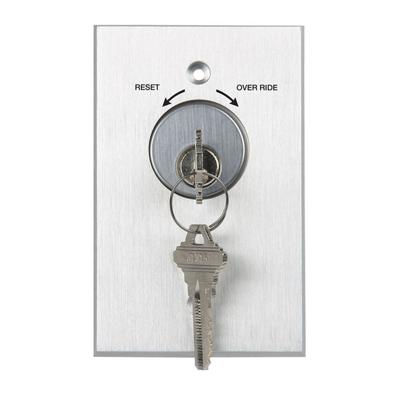
1. Place the mortise cylinder through the 1-3/16" hole in
the center of the aluminum faceplate.
2. Mount the cylinder/switch bracket on the reverse side
of the faceplate as shown in the profile photos below.
Make sure that the teeth are positioned inside the
grooves along the cylinder.
Attach the cylinder nut to fasten.
3. Insert the switch(es) into the 1/2" holes located on
the bracket below the cylinder. For ideal installation
thread the top nut an 1/8" down and tighten bottom
nut using a 9/16" wrench.
Rear Profile
1-1/2"
(38mm)
27/32" (Narrow)
(21.5mm)
4-3/4"
(120.6mm)
3" (76mm)
1-11/16" (Narrow)
(43mm)
Narrow Style = 960N
IS960
Side Profile
1-3/16" (30mm)
1/2" (13mm)
Switch Mounting
Hole
© 2018 dormakaba Canada Inc. | dormakaba Group
www.rutherfordcontrols.com • PHONE: 1.800.265.6630 • FAX: 1.800.482.9795 • E-MAIL: sales_rci@dormakaba.com
TAMPER-RESISTANT KEYSWITCH
Instructions
4. Make wire connections per illustrations below.
5. Fasten keyswitch to electrical box with the tamper-
proof 6-32 machine screws and spanner hand tool
supplied.
Red N/C
2-3/4" (70mm)
1-3/4"
(44mm)
SPDT Wire Connection
(SPDT)
Optional DPDT Switch Connection
N/O 2
(White)
N/O 1
(White)
Common 1
Common 2
(Black)
(Black)
960
Black (Common)
Red N/O (Maintained)
Green N/O (Momentary)
N/C 2
(Red)
N/C 1
(Red)
PCN18003
R01-18TG
Advertisement
Table of Contents

Subscribe to Our Youtube Channel
Related Manuals for Dormakaba RCI 960


Summary of Contents for Dormakaba RCI 960
- Page 1 1-11/16" (Narrow) (44mm) (43mm) N/C 2 (Red) Narrow Style = 960N N/C 1 (Red) Common 1 Common 2 (Black) (Black) IS960 © 2018 dormakaba Canada Inc. | dormakaba Group PCN18003 www.rutherfordcontrols.com • PHONE: 1.800.265.6630 • FAX: 1.800.482.9795 • E-MAIL: sales_rci@dormakaba.com R01-18TG...
- Page 2 & CSA 28 or 40 1A @ 250 VAC/VDC & CSA 28 or 40 NOTE: Specifications are subject to change without notice. © 2018 dormakaba Canada Inc. | dormakaba Group www.rutherfordcontrols.com • PHONE: 1.800.265.6630 • FAX: 1.800.482.9795 • E-MAIL: sales_rci@dormakaba.com...
Need help?
Do you have a question about the RCI 960 and is the answer not in the manual?
Questions and answers