
Related Manuals for ARC MWMR-250

Summary of Contents for ARC MWMR-250
-
Page 1: Table Of Contents
Issue Date: 5/2/2020 WIRELESS DIMMER MINI WALL MODULE MWMR-250 CONTENTS 1. Overview and features Page 2. 2. Diagrams Page 3. 3. Installation – Wiring Page 4. 4. Pairing / Un-pairing device Page 7. 5. Non-Dimmable / Trailing & Leading Edge setup Page 9. -
Page 2: Overview And Features
12V electronic transformers • 12V inductive transformers • Dimmable and non-dimmable energy saving lamp • Dimmable and non-dimmable LED Not compatible to: Fluorescent lamp Momentary / push button switch ARC Code switch system product range OVERVIEW AND FEATURES OVERVIEW AND FEATURES... -
Page 3: Diagrams
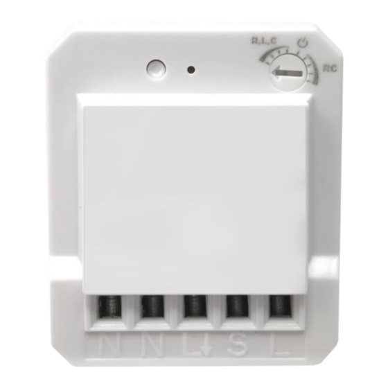
Issue Date: 5/2/2020 2. Diagrams Notes for the diagrams: - Terminal for neutral wire L - Output terminal for load wire - Terminal for power supply to the switch - Terminal for live wire ⚫ Strip the solid wires (rigid conductor only) at least 7mm then connect the wires as per diagrams below, ensure terminals are properly tightened and no bare wire is visible. -
Page 4: Installation - Wiring
Issue Date: 5/2/2020 3. Installation - Wiring Cut off main power before installing and wiring. Current existing house wiring should be as below. INSTALLATION - WIRING... - Page 5 Issue Date: 5/2/2020 Add mini module with one way operation 1. Connect permanent Live wire into module terminal ‘L’. 2. Connect Neutral wire into module terminal ‘N’. 3. Connect wire from module terminal ‘ L & N’ to Load. 4. Connect switch Live wire from module terminal ‘S’ into switch ‘L1’ terminal. 5.
- Page 6 Issue Date: 5/2/2020 Add mini module with two way operation Two Way Operation 1. Switch 1 and 2 must be connected together with wires into ‘L1 & L2’ terminal. 2. Connect permanent Live wire into module terminal ‘L’. 3. Connect Neutral wire into module terminal ‘N’. 4.
-
Page 7: Pairing / Un-Pairing Device
Issue Date: 5/2/2020 4. Pairing / Un-pairing Device AIRING Pairing using LEARNING MODE: 1. Press ‘Learn’ button once (LED on module will flash), this will enter learning mode. 2. With a remote control press the ‘ON’ button; LED on module will flash to confirm that the remote control is now paired. - Page 8 Issue Date: 5/2/2020 AIRING Removing single Device: 1. Press ‘Learn’ once (LED on module will flash), this will enter learning mode. 2. With a remote control press the ‘OFF’ button intended to be un-paired; LED on module will flash to confirm that the remote control is un-paired. LEARING EMORY Removing all memory stored in the module.
-
Page 9: Non-Dimmable / Trailing & Leading Edge Setup
Issue Date: 5/2/2020 5. Non-Dimmable / Trailing & Leading Edge Setup Initial factory pre-set is at ‘Leading Edge’ Position IMMABLE LOAD On-Off Function for non dimmable load. Benefit to change from dimmable to non dimmable load without changing the module and operates normally for On-Off function. ⚫... - Page 10 Issue Date: 5/2/2020 RAILING EADING INIMUM RIGHTNESS EVEL Adjust the rotary switch on the top light hand corner to select trailing or leading edge by trimmer resistor. Leading Edge ⚫ Adjust rotary switch counterclockwise to the very end of R,L,C position, LED on module will blink once to confirm the mini wall module is properly setup under leading edge.
-
Page 11: Operation
Issue Date: 5/2/2020 6. Operation Mini module is compatible to “Self Learning” system and M series remote control. Please refer to the relevant user guide for detailed operation. Operation via Rocker Switch: Turn the load ON: Toggle switch once to turn ON load. Turn the load OFF: Toggle switch once again to turn OFF load. - Page 12 Issue Date: 5/2/2020 Rocker Switch Two way operation: Turn the load ON: Toggle switch once to turn ON load. Turn the load OFF: Toggle switch once again to turn OFF load. Operation example: Switch 1 is located downstairs & Switch 2 is located upstairs. While going up the stairs, toggle “Switch 1”...
-
Page 13: Specifications
Issue Date: 5/2/2020 7. Specifications Input Rating: 230V~50Hz Output Rating: Supported Load Wattage “Trailing edge” for resistive loads (R) • Conventional incandescent and halogen light 20-250W / 230V~ source “Trailing edge” for resistive-capacitive loads (RC) • 20-250W / 230V~ Electronic transformers •... - Page 14 Issue Date: 5/2/2020 Dimension (L x W x H) 45 x 40 x 15.2mm Weight: 20 g NOTE ⚫ Please leave minimum of 1.5 meters in-between 2 or more modules. ⚫ When inserting module into back box make sure excess wires do not cover module’s back side.
Need help?
Do you have a question about the MWMR-250 and is the answer not in the manual?
Questions and answers