
Related Manuals for MTD Yard Machines 450 Series


Summary of Contents for MTD Yard Machines 450 Series
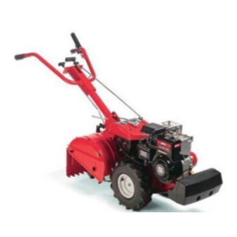
- Page 1 OPERATOR’S MANUAL REAR TINE TILLER MODEL 450 Series IMPORTANT: READ SAFETY RULES AND INSTRUCTIONS CAREFULLY MTD PRODUCTS LTD. P.O. BOX 1386 KITCHENER, ON N2G 4J1 PRINTED IN THE U.S.A. 772C0731 (10/04)
-
Page 2: Table Of Contents
Service is available, WITH PROOF OF PURCHASE, through your local authorized service dealer. To locate the dealer in your area; In the U.S.A.: Check your Yellow Pages, or contact customer support listed about MTD LLC at P.O. Box 361131, Cleveland, Ohio 44136-0019, or call 1-800-800-7310 or 1-330-220-4683 or log on to our Web site at www.mtdproducts.com. -
Page 3: Important Safe Operation Practices
SECTION 1: IMPORTANT SAFE OPERATION PRACTICES WARNING: This symbol points out important safety instructions which, if not followed, could endanger the personal safety and/or property of yourself and others. Read and follow all instructions in this manual before attempting to operate your tiller. Failure to comply with these instructions may result in personal injury. - Page 4 9. Look down and behind and use care when in 20. Use only accessories and attachments approved reverse or pulling machine towards you. for this machine by the machine manufacturer. 10. Start the engine according to the instructions Failure to do so, can result in serious injury. found in this manual and keep feet well away from 21.
-
Page 5: Loose Parts
SECTION 2: LOOSE PARTS Handle Assembly Depth Stake Control Assembly All hardware needed for assembly is attached to the loose parts or the tiller. NOTE: NOTE: Cable tie not shown. -
Page 6: Assembly
SECTION 3: ASSEMBLY INSTRUCTIONS This unit is shipped WITHOUT IMPORTANT: ATTACHING DEPTH STAKE ASSEMBLY GASOLINE or OIL. After assembly, see separate 1. Tip the tiller forward so it rests on front engine manual for proper fuel and engine oil counterweight. recommendations. - Page 7 Slot Head Screw Slot Head Screw, Clutch Nut, Flat Washers Bail Flat Washers 1/4” Internally Threaded Threaded Tube Eyebolt Internally Threaded Tube Plastic Fitting Figure 3 Figure 4 ATTACHING THE CLUTCH CABLE ATTACHING THE CONTROL ROD Attach the clutch cable to the handle as follows (be •...
-
Page 8: Controls
A secondary cable adjustment is available if WARNING: NOTE: Do not put fingers under the you reach the point that additional adjustment is belt cover. needed. Remove the belt cover and move the hex nuts at the other end of the cable towards the end of the casing. -
Page 9: Operation
DEPTH STAKE HANDLE ADJUSTMENT The depth bar controls the tilling depth. Refer to The handle may be adjusted to be raised or lowered in SECTION 6: HOW TO USE YOUR TILLER on page line with the tiller. To adjust the handle position loosen the handle height adjustment crank a few turns. -
Page 10: How To Use Your Tiller
SECTION 6: HOW TO USE YOUR TILLER WARNING: Be certain the spark plug wire disconnected grounded Use This Transport Position against the engine when performing any Position adjustments. First Time 1” Tilling depth is controlled by the depth stake which can 3”... -
Page 11: Adjustments
SECTION 7: ADJUSTMENTS 1. Disconnect and ground out spark plug wire against WARNING: Never attempt to make any the engine. adjustments while the engine is running, except where specified in operator’s 2. Remove the belt cover as described in the belt manual. -
Page 12: Off-Season Storage
The spark plug should be cleaned and the gap reset Torx Screws Belt Cover every 25 hours of engine operation. Spark plug replacement is recommended at the start of each tiller season; check engine manual for correct plug type and gap specification. -
Page 13: Trouble Shooting Guide
3. Refer to the engine manual for correct engine NOTE: When storing any type of power equipment storage instructions. in an unventilated or metal storage shed, care should be taken to rustproof the equipment. Using a 4. Wipe tines with oiled rag to prevent rust. light oil or silicone, coat the equipment, especially 5. -
Page 14: Parts Lists/Pièces Détachées
19 49... - Page 15 REF. PART N°. DE N° DE RÉF. PIÈCE DESCRIPTION DESCRIPTION 611-0020 Wheel Shaft Ass'y 33T Arbre de roue 33 dents 611-0021 Tine Shaft Ass'y 18T Arbre de dents - 18 dents 611-0128 Jack Shaft Ass'y Arbre secondaire 611-0129 Input Shaft Ass'y Arbre 617-0058 Rev.
- Page 17 REF. PART N°. DE N° DE RÉF. PIÈCE DESCRIPTION DESCRIPTION 747-1152 Shift Rod Tige de changement de vitesses 649-0041 Upper Handle Assembly Guidon supérieur 649-0034 Lower Handle Ass'y Guidon inférieur 710-3005 Hex Bolt 3/8-16 x 1.25 Boulon hex. 3/8-16 x 1,25 710-3056 Hex Bolt 5/16-18 x 3.25 Boulon hex.
- Page 19 REF. PART N°. DE N° DE RÉF. PIÈCE DESCRIPTION DESCRIPTION 686-0111 Belt Cover Brkt Ass'y Support de couvercle de la courroie 710-0237 Hex Screw 5/16-24 x .625 Gr. 5 Vis à tête hexagonale 5/16-24 x 0,625 Qual. 5 710-0412 Hex Scr 1/4-28 x .75 Vis à...
-
Page 20: Warranty
TWO YEAR LIMITED WARRANTY For TWO YEARS from the date of retail purchase within Canada, MTD PRODUCTS LIMITED will, at its option, re- pair or replace, for the original purchaser, free of charge, any part or parts found to be defective in material or workmanship.
Need help?
Do you have a question about the Yard Machines 450 Series and is the answer not in the manual?
Questions and answers