Table of Contents
Advertisement
Quick Links
501 1ST STREET S | HACKENSACK, MN 56425
WWW.MANNLAKELTD.COM | BEEKEEPER@MANNLAKELTD.COM
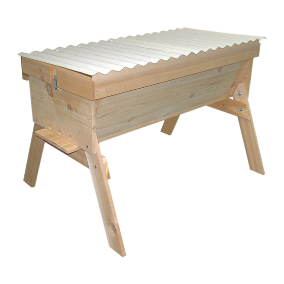
ECONOMY TOP BAR HIVE KIT
Mann Lake Ltd.'s Economy Top Bar Hive Kit comes
with everything you need to get started in one of the
fastest growing hobbies around. We use precision-
milled lumber and top-quality components to
ensure years of enjoyment.
TOOLS REQUIRED:
• Phillips Head Screwdriver
• 1/4" Hex Driver
• 7/16" Wrench
ITEM
DESCRIPTION
A
BOTTOM
B
FRONT/BACK
C
LH SIDE
D
RH SIDE
E
LEG
F
LEG SUPPORT
L
FOLLOWER BOARD
M
CARRIAGE BOLTS 2"
N
3/4" PAN HEAD SCREWS
Q
NUT 1/4"
R
WASHER 1/4"
S
WOOD SCREW 1 1/4"
T
WOOD SCREW 2"
W
DRAW LATCH
X
DRAW LATCH SCREW
Z
TOP BAR
WOOD GLUE RECOMMENDED
Note to Mann Lake Ltd. customer: While assembling your new product requires a few common tools, these instructions are intended
to supplement a basic mechanical literacy. If you have any questions regarding assembly, please call us at 800-880-7694.
MANN
LAKE
WE KNOW BEES
PHONE 800-880-7694 | FAX 218-675-6156
PART #
QTY
WW-269-A
1
WW-269-B
2
WW-269-C
1
WW-269-D
1
WW-269-E
4
WW-269-F
2
WW-268
1
50-262
8
50-260
8
50-260
8
50-260
8
80-119
28
M
80-121
20
N
50-173
2
50-260
8
WW-167
28
A
B
B
T W
S
X
Q
R
F
C
D
Z
L
F
E
E
E
E
Advertisement
Table of Contents

Summary of Contents for MANN LAKE ECONOMY TOP BAR HIVE KIT
- Page 1 WOOD GLUE RECOMMENDED Note to Mann Lake Ltd. customer: While assembling your new product requires a few common tools, these instructions are intended to supplement a basic mechanical literacy. If you have any questions regarding assembly, please call us at 800-880-7694.
- Page 2 STEP #1 STEP #2 THIS END PROTRUDES 2” ATTACH THE FRONT AND BACK(B) TO THE LEFT AND RIGHT SIDES (C & D) USING ATTACH THE BOTTOM (A) USING TWELVE (12) 11/4” SCREWS (S). GLUE ALL CONNECTING EIGHT (8) 2” SCREWS (S). GLUE ALL CONNECTING JOINTS AND SURFACES. JOINTS AND SURFACES.
- Page 3 STEP #5 ATTACH THE DRAW LATCH (W) USING FOUR (4) SCREWS (X). SET FOLLOWER BOARD (L) AND TOP BARS (Z) INSIDE. SET COVER ON TOP. ECONOMY TOP BAR HIVE COVER ITEM DESCRIPTION PART # HOOD FRONT WW-269-G HOOD BACK WW-269-H HOOD SIDE WW-269-I HOOD SIDE BLANK...
- Page 4 STEP #1 STEP #2 FLUSH 1” FLUSH ON SIDES FLUSH ON SIDES AND TOP AND TOP ATTACH THE SIDE BLANKS (J) TO THE SIDES USING FOUR (4) 2” SCREWS ON THE OUTSIDES AND ATTACH FRONT (G), BACK (H) AND SIDES (I) TOGETHER USING EIGHT (8) 2” EIGHT (8) 11/4”...
Need help?
Do you have a question about the ECONOMY TOP BAR HIVE KIT and is the answer not in the manual?
Questions and answers