Table of Contents
Advertisement
Snap-on Equipment
INSTALLATION AND OPERATING MANUAL
READ THOROUGHLY BEFORE INSTALLING, SERVICING
OR MAINTAINING THE LIFT.
SAVE THIS MANUAL
INSTALLATION and OPERATION MANUAL
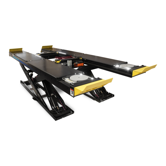
12K SCISSOR LIFT
EELR501A, EELR525A
EELR709A, EELR724A
Nov. 2019 REV.F
309 EXCHANGE AVENUE, CONWAY, ARKANSAS, 72032
TEL: 501-450-1500 FAX: 501-450-1585
EAZ0080V44A
1 of 73
Advertisement
Table of Contents

Related Manuals for Snap-on Equipment EELR501A

Summary of Contents for Snap-on Equipment EELR501A
- Page 1 INSTALLATION AND OPERATING MANUAL READ THOROUGHLY BEFORE INSTALLING, SERVICING OR MAINTAINING THE LIFT. SAVE THIS MANUAL INSTALLATION and OPERATION MANUAL 12K SCISSOR LIFT EELR501A, EELR525A EELR709A, EELR724A Nov. 2019 REV.F 309 EXCHANGE AVENUE, CONWAY, ARKANSAS, 72032 TEL: 501-450-1500 FAX: 501-450-1585 EAZ0080V44A...
-
Page 2: Table Of Contents
TABLE OF CONTENTS 1.0 IMPORTANT SAFETY INSTRUCTIONS ............4 2.0 SAFETY WARNING DECALS ............... 6 3.0 SPECIFICATIONS ..................7 4.0 CONTENTS ....................9 5.0 TOOLS REQUIRED FOR INSTALLATION OF LIFT ........9 6.0 INSTALLATION OVERVIEW ............... 10 7.0 INSTALLATION INSTRUCTIONS ............... 10 7.1 Surface Mount Bay Layout .............. - Page 3 12.1 Lubrication SPECS ................42 12.2 Mechanical Safety Locks ..............43 12.3 Air Cylinders, Air Lines, Valve and Fittings ........44 12.4 Hydraulic Power Pack and Hose ............. 44 12.5 Hydraulic Cylinders ................45 12.6 Check Base Frames and Approach Ramps ........45 12.7 Fasteners ...................
-
Page 4: Important Safety Instructions
1.0 IMPORTANT SAFETY INSTRUCTIONS When using this lift, basic safety precautions should always be followed, including the following: 1. Only trained and authorized personnel should operate the lift or rolling jacks. Do not allow customers or bystanders to operate the lift or be in the shop area while lift is in use. 2. - Page 5 READ AND SAVE THESE INSTRUCTIONS Installation shall be performed in accordance with ANSO/ALI ALIS, Safety Requirements for Installation and Service of Automotive Lifts. For additional safety instructions regarding lifting, lift types, warning labels, preparing to lift, vehicle spotting, vehicle lifting, maintaining load stability, emergency procedures, vehicle lowering, lift limitations, lift maintenance, good shop practices, installation, operator training and owner/employer responsibilities, please refer to “Lifting It Right”...
-
Page 6: Safety Warning Decals
2.0 SAFETY WARNING DECALS 6 of 73... -
Page 7: Specifications
3.0 SPECIFICATIONS Maximum Capacity: 12000 lbs 5443 kg Overall Width: 90 Inches 2288 mm 242 - 294 Inches 6143 - 7467 mm Overall Length: Maximum Raised Height: 70 Inches 1772 mm Minimum Lowered Height: 12-1/4 Inches 311 mm Runway Width: 24 Inches 612 mm Minimum 4 Wheel Alignment W/B:... - Page 8 Figure 2 - Lift Dimensions (Side View) Figure 3 - Lift Dimensions (Back View) 8 of 73...
-
Page 9: Contents
4.0 CONTENTS The complete lift is contained in two (2) packages: 1. The main structural components are pre-assembled and packaged on top of each other. 2. The remaining parts are packed in a console/accessory box. Refer to the packing slip inside the accessory box for a list contents. -
Page 10: Installation Overview
6.0 INSTALLATION OVERVIEW This is the order in which this installation is to take place: 1. Layout the Bay 2. Unpacking the Lift 3. Inspect the Lift 4. Connect Hydraulic Lines 5. Connect Air Lines 6. Connect Electrical 7. Initial Run of Lift 8. -
Page 11: Surface Mount Bay Layout
Surface Mount Bay Layout NOTE: Leave any additional room for desired aisle work area. Recommended clearance around the lift is a minimum of three (3) feet. Ensure clearance conforms to local building and fire codes. Recommended overhead clearance is a minimum of twelve (12) foot ceiling providing 6 feet for the maximum lift height and 6 feet for the supported vehicle. -
Page 12: Baseframe Location
Base frame Location IMPORTANT: DO NOT CUT THE SHIPPING STRAPS HOLDING EACH SCISSOR ASSEMBLY TOGETHER UNTIL INSTRUCTED TO DO SO. 1. With reference to Figure 4, the installer should determine the most suitable location in the bay for the lift. 2. -
Page 13: Flush Mount Bay Layout (Rear Mount Console)
Flush Mount Bay Layout (Rear Mount Console) NOTE: Leave any additional room for any desired aisle or work area. Recommended clearance around the lift is a minimum of three (3) feet. Ensure clearance conforms to local building and fire codes. Recommended overhead clearance is a minimum of twelve (12) foot ceiling providing 6 feet... -
Page 14: Flush Mount Bay Layout (Front Mount Console)
Flush Mount Bay Layout (Front Mount Console) NOTE: Leave any additional room for any desired aisle or work area. Recommended clearance around the lift is a minimum of three (3) feet. Ensure clearance conforms to local building and fire codes. Recommended overhead clearance is a minimum of... -
Page 15: Unpacking The Lift
Unpacking the Lift Unpack the console and place it in the desired location at the rear of the lift, see Figure 1 and Figure 4. The console can be placed on either the left or right hand side of the lift. Unpack the runways and lay each base frame along the chalk lines. -
Page 16: Hydraulic Connections
Hydraulic Connections 1. Install Hydraulic Equalization Circuit Open the rear access cover of the console. Install the hydraulic equalization circuit on the right side wall of console by using provided hard wares. See Figure 9. Figure 9 – Hydraulic Circuit Installation 2. - Page 17 3. Connect Hydraulic Hoses From Console to Lift The hydraulic equalization circuit orientation and ports layout refers to Figure 11. The primary supply lines and equalizing lines from each runway are: Left Side (L): Right Side (R): (“C” for “Cylinder” and “EQ” for “Equalize”) Figure 11 Hydraulic Equalization Circuit - Unravel all hydraulic hoses and air lines from each runway, and connect each hydraulic lines as shown in Figure 11 and Figure 12.
- Page 18 Figure 12 - Hydraulic Connections 18 of 73...
-
Page 19: Air Safety And Auxiliary Air Connections
Air Safety and Auxiliary Air connections WEAR SAFETY GOGGLES AND PRACTICE CAUTION WHILE WORKINGWITH COMPRESSED AIR. 1. Install FRL and Swivel Tee Find the FRL (Filter/Regulator/Lubricator) assembly with elbow and Swivel Tee poly from accessory box, see Figure 13 a). - Mount FRL assembly on the right side of the console by using provided hard wares, see Figure 13 b). - Page 20 Figure 14 – Air Control Valve and Air lines 3. Connect Air Hoses and Run Testing - Uncoil the polytubes under each runway that is connected to the safety lock release air cylinder shown on Figure 15. Route these two lines from base frames to the union ‘Y’ connector in the console.
- Page 21 Figure 15 - Air Safety & Auxiliary Air Connections For a flush mount installation with a front mount console requiring a hose extension, refer to installation instructions 6-4189 provided with kit EAK0299T19A 21 of 73...
-
Page 22: Electrical Connections
Electrical Connections DANGER! – Ensure that electrical connections are completed by a licensed electrician. Electrical shock can cause serious injury or even death. Figure 16 - Console Circuit Connections CAUTION: MOTOR NOT PROTECTED BY THERMAL OVERLOAD--- EXTERNAL OVERHEAT PROTECTION IN ACCORDANCY WITH CE CODE, PART I, MUST BE PROVIDED. - MINIMUM CIRCUIT AMPACITY OF CONDUCTOR IS 20 A. -
Page 23: Initial Operation
Initial Operation EQUALIZER VALVES ON THE HYDRAULIC EQUALIZATION CIRCUIT MUST REMAIN IN THE CLOSED POSITION DURING NORMAL OPERATION. REFERENCE FIGURE 17 (b). REAR BOLSTER BAR AND JACK BEAMS CANNOT BE INSTALLED UNTIL THE LIFT HAS BEEN BLED. THE FOLLOWING PROCEDURE SHOULD BE PERFORMED WITHOUT LOAD ON THE LIFT. 1. -
Page 24: Bleed The Hydraulic System
Bleed The Hydraulic System 7.10 EQUALIZER VALVES ON THE HYDRAULIC EQUALIZATION CIRCUIT MUST REMAIN IN THE CLOSED POSITION DURING NORMAL OPERATION. FAILURE TO CLOSE VALVES DURING NORMAL OPERATION MAY DAMAGE LIFT STRUCTURE.THE FOLLOWING PROCEDURE SHOULD BE PERFORMED WITHOUT LOAD ON THE LIFT. 1. -
Page 25: Level And Support
Level and Support 7.11 NOTICE - CORRECT LEVELING IS IMPORTANT TO ENSURE THE PROPER OPERATION OF THE LIFT. TAKE PRECAUTIONS TO ENSURE ACCURATE LEVEL READINGS WHEN PERFORMING THIS PROCEDURE. IT IS HIGHLY RECOMMENDED TO PERFORM THE LEVELLING PROCEDURE USING A SELF-LEVELLING LASER LEVEL. -
Page 26: Anchoring Procedure
Note: These bolts must be removed once the shims are installed under the base correctly (same as the center bolt on the base). Figure 19 – Shimming Anchoring Procedure 7.12 CAUTION! WEAR PERSONAL PROTECTIVE EQUIPMENT (PPE) AND PRACTICE CAUTION WHILE DRILLING CONCRETE. Figure 20 –... -
Page 27: Grouting Procedure (Optional)
Grouting Procedure (Optional) 7.13 1. Pour grouting under the load area of each base frame as shown in Figure 21. Ensure that grout is evenly distributed under the frame and finish the edges with a 45 degree chamfer. Refer to specific grouting instructions on the package. -
Page 28: Accessory Installation
8.0 ACCESSORY INSTALLATION Position lift to a comfortable working height and place the lift on the mechanical safety locks to continue with the installation. Installation of Wheel Stops Install the front wheel stops located in the accessory box by using three M14 hex bolts, washers, and hex nuts located in the hardware kit for each runway. -
Page 29: Installation Of Rear Bolster Bar
Installation of Rear Bolster Bar Install the bolster bar to the rear end of both runways by using eight M24 Hex bolts, washers and Hex nuts located in the hardware kit. See Figure 23. Engine crane or floor jack will be required to lift and position the bolster bar. It may be necessary to lower the lift to accommodate the installation. -
Page 30: Position Of Approaching Ramps
Position of approaching ramps Position the approaching ramps in the desired location NOTE: RAMP OPERATION INSTRUCTION REFERENCE TO THE SECTION 19.0. Raise the lift up to the top lock position; Open the ramps package to get two fully retracted ramps (9-2180), position them in the desired location, see Figure 25. - Page 31 Lower the lift and verify sufficient clearance between the deck ends and the approach ramps. Review the function of the transition ramps, if the ramp is too lower, use supplied shims to shim up desired height (total can raise up 60mm or 2-3/8"), and ensure the transition ramp functioning.
-
Page 32: Position Of Jack Beams
Position of Jack Beams Refer to Figure 1, Position two Jack beams on scissor lift, make sure that the air/ hydraulic pump of front jack beam oriented to front and the air/ hydraulic pump of rear jack beam oriented to rear for easy operation. And also make sure that all rollers seat on the rail on both sides of runways, see Figure 29. - Page 33 Figure 31 – Connection of Air Recoil Hose 33 of 73...
-
Page 34: Installation Of Line Covers
Installation of Line Covers 1. Install line covers once console is installed and hydraulic lines are routed. 2. Position line cover “A” behind the base frames as shown. 3. Place line cover “B” close to line cover “A”, and adjust the position to make the square holes of the line cover “B”... -
Page 35: Installation Of Extension Line Covers
8.7 Installation of Extension Line Covers Installation of extension line covers ( Hose extension kit ) Install line covers “E” and “D” to form an angle (as shown) that will route the hoses to the front of the lift. Position 5 line covers “C” after line cover “D”... -
Page 36: Install Front Turntables
9.0 INSTALL FRONT TURNTABLES Installation of Front Turntables Position the lift at a comfortable working height and lower onto a mechanical safety lock. Place each front turntable assembly on the front alignment pan of the runway. Moving lock handles of the turntables should be oriented to the outside of lift, See Figure 34 (a). If the surface of turntable is not flat with the runway, the turntable support can be adjusted to See Figure 34 (b). - Page 37 Do not insert fingers in the front or rear alignment pan cut-out, See Figure 35 and Figure 36. During normal use, the front turntables and rear slip plates may move rapidly, Creating pinch points for your fingers or hands. Keep hands clear of these pinch points when moving it.
-
Page 38: Final Procedures
10.0 FINAL PROCEDURES Check of Assembled Lift 10.1 1. Final dimension check after anchoring. 2. Check for air and hydraulic leaks. Check hydraulic fluid level in reservoir and top up as required using appropriate fluid. 4. Check all fasteners, tighten if necessary. 5. -
Page 39: Lift Operation
11.0 LIFT OPERATION Raising the Lift 11.1 1. If the lift is equipped with sliding Jack Beam(s), be sure that the Beam(s) are positioned at the front or mid travel of the lift, fully down, and with the risers removed and stored. Never store Jack Beams at the rear of the lift. -
Page 40: Approaching Ramp Operation
Approaching Ramp Operation 11.3 This sliding approaching ramp have three following working positions, Customer can chose any one by their service needs. a) Fully Retracted Position See Figure 37, this position is for customer with limit space in garage, which need to fully retract the ramp to close garage door. - Page 41 - After day work, if more clearance space needs for close the garage door, lift the end sliding ramp end and push back fully, than lift the middle ramp up slightly and push back to fully retract position see Figure 37. Figure 38 –...
-
Page 42: Recommended Inspection And Maintenance
Where pneumatic oil is required > Snap-On air motor oil IM1PT If you are not completely familiar with automotive lift maintenance procedures, STOP. Contact Snap-on Equipment Technical Support for instructions. To avoid personal injury, permit only qualified lift service personnel to perform maintenance on this equipment. -
Page 43: Mechanical Safety Locks
Mechanical Safety Locks 12.2 Watch and listen to safety locks operation during lift operation, to ensure that locks move as required, Stop using the lift if any malfunction or damage is observed. - If the safety locks on both sides sound not even or unsynchronized, bleed the hydraulic system again, reference to Section 7.10. -
Page 44: Air Cylinders, Air Lines, Valve And Fittings
Air Cylinders, Air Lines, Valve and Fittings 12.3 Check FRL (Filter/Regulator/Lubricator) in the right side of console. Drain water trap filter bowl and adjust oil feed according to manufacturer’s instructions. Drain water bowl on lift supplied water separator. Press valve at the bottom of the bowl to clear. Check operation of air release valve for air leaks. -
Page 45: Hydraulic Cylinders
If loose, re-torque base frame anchors to 110 ft-lb and approaching ramp AT BASE FRAMES anchors to 55 ft-lb. If anchors do not tighten to required torque, or continue to loosen, contact Snap-on Equipment Technical Support. Verify proper embedment of anchors after tightening. The Ø3/4”×5-1/2” wedge anchors supplied must have a NOTE: minimum embedment of 3-1/4”... -
Page 46: Runways
Runways 12.9 12.9.1 CHECK RUNWAYS Check runways for damage or abnormal deformation. If such conditions exist, contact Snap-on Equipment Technical Support. 12.9.2 INSPECT JACK BEAM TRACKS Inspect rolling jack / oil drain pan tracks for cleanliness, corrosion, excessive wear or damage. Clean dirty tracks. -
Page 47: Lubrication Of Pivot Point And Sliders
Lubrication of Pivot Point and Sliders 12.13 In some instances, a clicking noise can be heard from the pivot points and rear slides of the scissor lift. This noise is a result of low contact pressure on the bearing surface that creates a stick-slip situation. - Page 48 • For all bushing locations, spray the lubrication between the shaft and the bushing (Figure 44). Spray all accessible locations of the shaft on either side of the bushings, example in Figure 45. Figure 44 Figure 45 48 of 73...
- Page 49 • For all slider locations on the base frame (Figure 46) and under the runway (Figure 47), lubricate the shaft of the slider (1), the travel path of the slider (2) and the slider face Figure 46 Figure 47 49 of 73...
-
Page 50: Lock Out And Tag Out Instructions
Lock Out and Tag Out Instructions 12.14 IMPORTANT: This machine does not have integral devices that will isolate the electrical, pneumatic, stored and hydraulic energy source. Appropriate isolation or blocking devices must be used that have the provisions to be switched in the off position and locked in that position. - Page 51 - ISOLATION AND VERIFICAITON PROCEDURES: ISOLATION AND VERIFICATION PROCEDURES: LOCKOUT ENERGY TYPE PROCEDURE FOR LOCKING OUT LOCATION VERIFY PROCEDURES AND SOURCE AND OR RELEASING ENERGIES (TO BE COMPLETED BY END USER) VERIFY THAT THE LIFT IS CONTACTING THE SUPPLEMENTARY JACK STANDS, THE BLOCKS ARE SECURLY PLACED AND THE COME ALONG IS STORED...
-
Page 52: Emergency Operation
- RETURNING TO SERVICE: • Check the lift and the immediate area around the lift to ensure that nonessential items, tools and parts are removed and that the lift components are operationally intact. • Check the work area to ensure that all employees have been safely positioned or removed from the work area. - Page 53 Figure 48 – Image of descent valve 4) Locate the manual override thumbscrew (red) on the top of the descent valve (Applicable to the power packs with the manual override function). 5) Verbally indicate to all those involved that the lift will now be lowered. 6) Slowly turn the manual override thumbscrew in the counterclockwise direction until the lift starts to move.
-
Page 54: Trouble Shooting
13.0 TROUBLE SHOOTING PROBLEM REASON SOLUTION Bad fuse or contactor. Re place fuse or contactor. Motor does not run. Incorrect voltage to motor. Provide proper voltage to motor. Incorrect wiring. Have certified electrician check Motor switch is malfunctioning Replace motor switch. Motor burned out Re place motor. -
Page 55: Record Of Maintenance / Training
14.0 RECORD OF MAINTENANCE / TRAINING Records of all lift maintenance and operator training should be recorded in the following table. MAINTENANCE NOTES & TRAINING DATE PERFORMED 55 of 73... - Page 56 Snap-on Equipment PARTS LIST SAVE THIS MANUAL 12K SCISSOR LIFT EELR501A, EELR525A EELR709A, EELR724A Nov. 2019 REV. F 309 EXCHANGE AVENUE, CONWAY, ARKANSAS, 72032 TEL: 501-450-1500 FAX: 501-450-1585 EAZ0080V44A 56 of 73...
-
Page 57: Lift Parts List
15.0 LIFT PARTS LIST REPLACE WORN, DAMAGED OR BROKEN PARTS WITH PARTS APPROVED BY THE ORIGINAL EQUIPMENT MANUFACTURER ONLY. Figure 49 – Lift Parts Map 57 of 73... -
Page 58: Lift Parts List
Lift Parts List 15.1 ITEM# PART# DESCRIPTION QTY. 9-0284 BALL TRANSFER, FLANGE, BALL Ø25mm 9-2351 TOP DECK REMOVABLE WELDMENT 9-0288 PIN LOCKING - SLIP PLATE 9-0292 PULLOUT STEP 9-0315 HEX NUT M14 9-2383 PIN CENTER 9-0343 NYLON BLOCK TOP 9-0344 PIN SLIDING END BOTTOM 9-0345 PIN SLIDING END TOP... -
Page 59: Ramp Parts List
Ramp Parts List 15.2 Figure 50 – Ramp Parts Map RAMP SPARE PART LIST (Assembly number: 9-2180): ITEM# PART# DESCRIPTION QTY. 9-0130 FLAT WASHER Ø6 GB/T 95-2002 9-0131 SPRING LOCK WASHER Ø6 GB/T 93-1987 9-0425 HEX NUT M16 GB/T 41-2000 9-2219 HEX BOLT M16X2X65L GB/T 5781-2000 9-0554... - Page 60 ITEM# PART# DESCRIPTION QTY. 9-2186 MAIN RAMP TOP 9-2187 RAMP SIDE WALL-LEFT 9-2188 RAMP SIDE WALL-RIGHT 9-2208 MAIN RAMP MOUNTING BAR 9-1997 MAIN RAMP STIFFENER 9-2189 MAIN RAMP MOUNTING BAR 9-2192 END SUPPORT 9-2191 RAMP GUIDE PLATE 9-2156 BACK STOP BAR 9-2206 RAMP GUIDE PLATE 9-2190...
-
Page 61: Hydraulic And Air Line Assembly
16.0 HYDRAULIC AND AIR LINE ASSEMBLY Hydraulic Line Routing Map 16.1 Figure 51 – Hydraulic Items Map 61 of 73... -
Page 62: Hydraulic Line Routing Parts List
Hydraulic Line Routing Parts List 16.2 ITEM# PART# DESCRIPTION QTY. 9-0588 ELBOW-90° 3/8" NPT M / JIC-06-M 9-0594 90° ELBOW WITH NUT, JIC-06-M 9-0602 HYDRAULIC HOSE -REAR CYLINDER 9-0603 HYDRAULIC HOSE -BASE FITTING 9-0604 HYDRAULIC HOSE -PRI. CYL. BOTT 9-0605 HYDRAULIC HOSE -PRI. -
Page 63: Hydraulic Circuit Parts List
Hydraulic Circuit Parts List 16.4 ITEM# PART# DESCRIPTION QTY. 9-0590 HYDRAULIC EQUALIZATION CIRCUIT EAH0061V41A PIPE JOINT YBZ3-EH1/1-04 9-0601 HYDRAULIC HOSE - POWER PACK 9-0656 HYD. CIRCUIT MOUNT TOP 9-0657 HYD. CIRCUIT MOUNT BOTTOM 1-04888A HEX. BOLT M5x35L 9-0659 FLAT WASHER Ø5 9-0660 SPRING WASHER Ø5 1-18988A... -
Page 64: Air Line Routing Map
Air Line Routing Map 16.6 Figure 53 – Air Hose Assembly 64 of 73... -
Page 65: Console Assembly
17.0 CONSOLE ASSEMBLY Electrical and Control Panel 17.1 Figure 54 – Electrical and Control Panel Item # Part # Description Qty. EAE0076V19A Push Button 1NO with Arrow EAE0073V39A Part of push button EAE0073V40A Part of push button — Air Valve Assembly 6-4275 Air Control Valve 9-0619... - Page 66 17.2 TERMINAL ASSEMBLY FOR 12K ALI CONSOLE THE DETAIL Item # Part # Description Qty. EAK0346V15A TERMINAL ASSEMBLY FOR 12K ALI CONSOLE — EAE0070V26A Terminal ZDU 2.5-2/3AN 2.5 mm² EAE0070V28A Terminal Cover ZAP/TW7 EAE0073V10A Terminal, ZDU 4-2/4AN, 4mm2 EAE0073V12A Terminal Cover, ZAP ZDU4-2/4AN EAE0073V13A Terminal marker,5x6 mm,Print:1,2,White EAE0073V26A...
-
Page 67: Console: Pneumatic & Filtering System
Console: Pneumatic & Filtering System 17.3 Figure 55 – Pneumatic & Filter System Item # Part # Description Qty. FRL Assembly 9-0613 FRL (Filter / Regulator / Lubricator) , JAC2000-02 9-0615 90° Elbow 1/4" NPT M-F Air Valve Assembly 6-4275 Air Control Valve 9-0619 Swivel Elbow, EPL0601 (1/8”... -
Page 68: Console Box Assembly
Console Box Assembly 17.4 Figure 56 – Console Box Assembly * Note: may not be exactly as shown. Item# Part# Description Qty. EAS2215V02A CONSOLE BOX WELDMENT EAM0113V30A REAR COVER EAS2168V03A ELECTRICAL BACK PLATE COVER WELDMENT EAM0113V31A TOP COVER EAS2215V03A DOOR WELDMENT 8-73637A FLAT LOCK, MS730 includes... -
Page 69: Console Labeling
Console Labeling 17.5 Figure 57 – Console Labeling 69 of 73... -
Page 70: Power Pack
Power Pack 17.6 Figure 58 – Power Pack Assembly ITEM# PART# DESCRIPTION QTY. EAA0407T21A COMPLETE POWERPACK ASSEMBLY EAH0061V40A SOLENOID VALVE LSV-08-2NCP EAE0080V13A COIL 10148-79 EAE0080V14A MOULDED DIN CONNECTOR EAH0061V41A PIPE JOINT YBZ3-EH1/1-04 EAH0061V42A RELIEF VALVE LHRV-08-42 EAH0061V43A CHECK VALVE DF08-01-00 EAE0080V15A ELECTRICAL CABLE 610MM... -
Page 71: Accessory
18.0 ACCESSORY Line Covers and Nails 18.1 The Layout of line covers and Nails distribution refer to Figure 32. ITEM# PART# DESCRIPTION QTY. EAS2168V14A LINE COVER A WELDMENT (RAL1023 yellow) EAS2168V15A LINE COVER B WELDMENT (RAL1023 yellow) EAS2168V16A LINE COVER C WELDMENT (RAL1023 yellow) 1-10789A HEXAGONAL EXPANSION SCREW... -
Page 72: Shim Kit
8-0385 POLYTUBE 10mm OD 25ft 6-4190 10mm PUSHLOCK UNION 8-0384 POLYTUBE 6mm OD 45ft 6-4187 6mm PUSHLOCK UNION Shim kit 18.6 ITEM# PART# DESCRIPTION QTY. EAK0299T41A SCISSOR LIFT SHIM KIT (included) * If additional shims are required, please order the above item #. Contains the following: SHIM PLATE, 1/16"... - Page 73 Contains the following: QTY. DESCRIPTION EAA0453T05A 12K SS POWERPACK ASSY 230V/1PH EAK0346V12A BRACKET KIT FOR INSTALLING POWER UNIT WITH 14L TANK JBC64368000 INSTALLATION INSTRUCTION 73 of 73...
-
Page 74: Appendix Foundation Plan
APPENDIX Foundation Plan 74 of 73... - Page 75 Product Change Notice REV. DESCRIPTION DATE Add parts list cover on the page 55, and the foundation plan on DG07042 03JUN2019 the page 72. DG07067 Update the line cover on page 34, 70. 21OCT2019 Update the console box in page 15、16、17、19、20、43、 DG07230 19NOV2019 61、62、64、66、67、68、69.
Need help?
Do you have a question about the EELR501A and is the answer not in the manual?
Questions and answers