
Summary of Contents for ILVE UHP665
- Page 1 U s er I nst r uct i ons , In s ta lla tio n , ma in ten an c e fo r • C O O K T O P S • • C O O K T O P S • cod.
- Page 2 IMPORTANT - PLEASE READ AND FOLLOW • Before beginning, please read these instructions completely and carefully. • Do not remove permanently affi xed labels, warnings, or plates from the product. This may void the warranty. • Please observe all local and national codes and ordinances. •...
-
Page 3: What To Do If You Smell Gas
Keeping appliance area clear and free from combustible materials, gasoline and other fl ammable vapors and liquids. I M P O R T A N T I N S T R U C T I O N All Appliances: Do Not Leave Children Alone - Children should not be left alone or unattended in area where appliance is in use. They should never be allowed to sit or stand on any part of the appliance. -
Page 4: Installation Instructions
I N S T A L L A T I O N I N S T R U C T I O N S This appliance shall only be installed by an authorized person. This appliance shall be installed in accordance with the manufactures installation instructions, IMPORTANT: this appliance must be installed in accordance with the norms in force of the country concerned. -
Page 5: Electrical Connection
E LECT RIC A L CONN EC TIO N The g as c o o k to p re q u ire s a 120 VAC , 60H z el ec tri ca l s u p p l y to o p e ra te th e elect roni c i gnit io n s y s t e m. -
Page 6: Performance Checklist
PERF O R MA NCE CH EC KL IS T Al l bur ne r s a re t e s t ed b ef ore l eavi ng th e factory. T h e re a re n o a d j u s tme n ts fo r th e b u r n ers if c onne c t e d a cc o rd in g t o t he i nf or mat i on on th e ra ti n g p l a te . - Page 7 A DA PTAT IO N OF THE PRESS URE R EG UL AT O R F OR US E WI T H DI F FE RE NT TY PE O F G AS The pres su re re gu la t o r s up pl i ed w it h t he app l i ance i s a c o n v e rti b l e t y p e p re s s u re re g u l at or for u se wit h Na tu r a l G a s a t a nom in al ou t let p ressu re o f 5”...
- Page 8 CHANGING THE INJECTORS AND ADJUSTING THE AIR TAB LE 2 B ur ne r I N P U T O R IF IC E S IMM E R P R IMA RY B Y-PA S S R ATE SIZ E R AT E A IR OR IFIC E...
- Page 9 A1) Bur ne r s o f th e h o b 1. Remove the grill, the caps and the burners from the worktop. 2. Lift the worktop. 3. Unscrew the screw “F” and remove the pipe “R”. 4. Unscrew the injectors (U) and replace them with those suitable for the gas used, supplied with the cooker. See TABLE 2. 5.
- Page 10 US ER M A NUAL IM PORTANT: keep children away from the appliance when it operates. Safety rules do not always cover any type of accident. The appliance must not be used for heating purposes. IM PORTANT: correct positioning of the brass fl ame distributor (d, Fi g. 7) is very important. For this purpose, ensure that the fl...
-
Page 11: Surface Burners
LI GHTI N G T HE GAS B URNERS First you have to choose the burner, through indication near the knob, then press the knob (A) controlling the desidered burner and turn it towards the left. It is i m portant to press t he k n o b f o r 1 0 s ec ond s. -
Page 12: Cooking Table
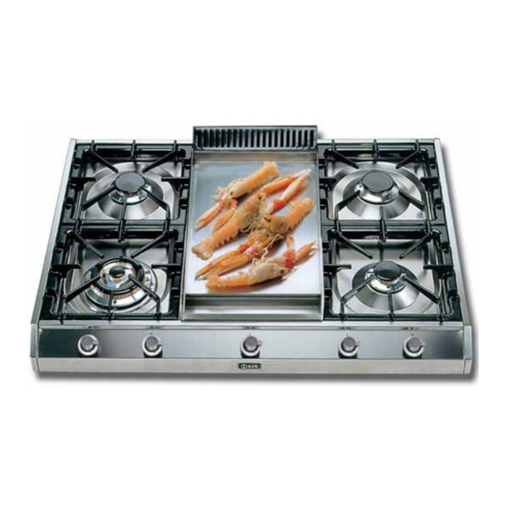
I NSTRU CT ION S FOR USE O F T HE GA S F RY- T OP The Fry-Top is composed of a special stainless steel plate (20/64” thick), specially designed to have temperatures evenly distributed over the whole surface so that it may be exploited to the full. The plate also has hygienic advantages. Another merit is the high heat accumulation of the plate, with very low heat loss. - Page 13 GA S B ARB E C UE Replace the burner cap A with the protected barbecue burner cap B. Before positioning the barbecue plate, ensure that the burner cap has been fi tted correctly and test lighting of the burner. To use the appliance, light the fl ame below the plate by means of the corresponding knob (see “Lighting the burners”) and ensure that the fl...
- Page 14 GAS C O O K TOP INSTALL ATIO N Remove the cooktop, gas pressure regulator, burner grates and burner caps from the shipping package. Lower the cooktop into the countertop cut-out opening. Center the cooktop in the opening and check that the front edge of cooktop is parallel to the front edge of the countertop.
-
Page 15: Gas Supply Connection
GA S S UP PLY CONNEC TIO N Assemble the fl exible metal connector from the gas supply pipe to the gas pressure regulator. You will need to determine the fi ttings required, depending on the size of your gas supply line, fl exible metal connector and shut-off valve. - Page 16 I NSTA LL ATI ON UH P4 5F.., UHP 65.., UHP 75.., UHP9 5 .. , UX LP 90F.., U HP123 0D.., UHP1 25.., UH F 4 0.. P roxi m i t y t o Si de Cab in et In stall atio n The cooktop may be installed directly to existing base cabinets.
- Page 18 I NSTA LL ATI ON FOR UHP 665.., UH P765.., UH96 5.., UHP1 2 6 5. . A hole of 1’’ 31/32 (5 cm x 5 cm) must be done on the top for power cable and gas conduit as shown in picture The supplied feet h= 0 5/16’’(0.8 cm) must be fi...
- Page 19 UHP1265 models there must be a minimum of 8” (20.3 cm) side clearance from the cooktop to such combustible surfaces above the 36” (91.4 cm) counter height. For UHP665 and UHP765 models there must be a minimum of 16” (40.64 cm) side clearance from the cooktop to such combustible surfaces above the 36” (91.4 cm) counter height.
-
Page 22: Wiring Diagram
W IR IN G D I AGR AM UHP4 5 F UHP65 (C/CN/D/DN) UHP75 (C/CN/D/DN) UHP95 (PC/PCN/PD/PDN/FC/FCN/FD/FDN/C/CN/D/DN) UHP1230 (D/DN) UHP125 (PC/PCN/PD/PDN/FC/FCN/FD/FDN) UHF40 – UHF40N UHF40 (F/FN/D/DN) UHP665 – UHP665D UHP965 - UHP965 (F/FD/PD/6/6D) UHP1265 (7/TD/F/FD) UHP765 - UHP765D... - Page 23 UXL P9 0 F - UX LP 90FD LEGEND M=Terminal board MA= Electrical ignition microswitch EL= Valve DS1= Electronic controller 00= Black 22= Red 33= White 45= Green 66= Blue K1= Earth wire terminal board N= Neutral L= Phase...
- Page 25 NOT ES...
- Page 26 NOT ES...
- Page 27 NO T ES...
- Page 28 EuroChef USA (866) 844-6566 / (631) 243-0111 CANADA A.G.I. SERVICE Phone: 450-963-1303 / 1-888-651-2534 Fax: 450-963-8985 email: info@aginternational.ca COOKE RS • OVE NS • H OB -C O O KE RS INDUSTRIA LAVORAZIONE VENETA ELETTRODOMESTICI S.p.A. Via Antoniana, 100 35011 Campodarsego (PD) - Italy Tel.
Need help?
Do you have a question about the UHP665 and is the answer not in the manual?
Questions and answers