Advertisement
Quick Links
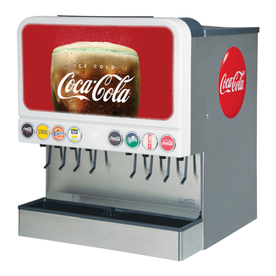
The following illustrates how to replace the existing fluorescent lighted merchandiser with the
new LED light Carma Merchandiser.
Kit Part Number Description
Lancer PN: 28-1005/01
82-5269
ACIB Merchandiser Kit, Carma, 22" - 6 Valve
82-5248
ACIB Merchandiser Kit, Carma, 30" - 8 Valve
82-6010
ACIB Merchandiser Kit, Carma, 30" - 10 Valve
ACIB 22"/30" Carma Merchandiser
1
Retrofit Kit
Instruction Sheet
CONTINUED ON NEXT PAGE
Advertisement

Summary of Contents for lancer ACIB 22 Series
- Page 1 LED light Carma Merchandiser. Kit Part Number Description 82-5269 ACIB Merchandiser Kit, Carma, 22” - 6 Valve 82-5248 ACIB Merchandiser Kit, Carma, 30” - 8 Valve 82-6010 ACIB Merchandiser Kit, Carma, 30” - 10 Valve Lancer PN: 28-1005/01 CONTINUED ON NEXT PAGE...
-
Page 2: Kit Contents
Merchandiser Graphic, 30”, 8/10 HHD, ZP Valve, Carma 06-4002 Wiring Diagram, Carma 05-3712/01 Badge, 22”/30” 6/8 Valve, Carma 05-4003 Badge, 30”, 10 Valve, Carma * part not used in 22” - 6 Valve Configuration (82-5269) Lancer PN: 28-1005/01 CONTINUED ON NEXT PAGE... - Page 3 10. Follow the wires of the fluorescent bulb bracket and disconnect from electrical box. Repeat for second fluorescent bulb bracket. 11. Unscrew the fluorescent bulb bracket and remove from unit. Repeat for second bulb bracket. Lancer PN: 28-1005/01 CONTINUED ON NEXT PAGE...
- Page 4 4. Remove the two (2) screws of the control box cover to remove from the unit. 5. Locate the positive (blue) and the negative (brown) wires of the existing LED Driver on the central connection terminal. Lancer PN: 28-1005/01 CONTINUED ON NEXT PAGE...
- Page 5 5. Slide the back, hooked tabs of the top Frame Assembly into the back slots of the left and right side Frame Assemblies. NOTE If necessary, use self-tapping screws to create custom hole pattern when attaching LED Driver to unit. Lancer PN: 28-1005/01 CONTINUED ON NEXT PAGE...
- Page 6 16. Plug-in the unit to test light panel operation before completing merchandiser assembly. NOTE If a water button installation is required, refer to the water button installation instructions (Lancer PN: 28- 3016) before going on to step 13. Lancer PN: 28-1005/01 CONTINUED ON NEXT PAGE...
- Page 7 5. Repeat Steps 2 - 4 for any other badges that have 9. Repeat steps 6 - 8 for the remaining Brand Badges. been removed or dislodged. 10. Install any necessary water button graphics above valves configured with a water push button. Lancer PN: 28-1005/01 CONTINUED ON NEXT PAGE...
- Page 8 NOTE If the merchandiser assembly ever gets scratched or scuffed, there is a paint marker (PN: 66-2000) available to touch up any marks or scratches. Contact Lancer Customer Service for more information on the mer- chandiser paint marker. Lancer PN: 28-1005/01...
-
Page 9: Wiring Diagram
Wiring Diagram Lancer PN: 28-1005/01 CONTINUED ON NEXT PAGE... -
Page 10: Spare Parts Kit
82-5289 Top Cover Assembly, Manual Ice Fill, 22”, 6 Valve, Carma Lancer Corp., 6655 Lancer Blvd., San Antonio, Texas 78219 - 800-729-1500 - Technical Support/Warranty: 800-729-1550 custserv@lancercorp.com - lancercorp.com - Manual PN: 28-1005/01 - September 2018 “Lancer” is the registered trademark of Lancer © 2018 by Lancer, all rights reserved.
Need help?
Do you have a question about the ACIB 22 Series and is the answer not in the manual?
Questions and answers