Table of Contents
Advertisement
Quick Links
Advertisement
Table of Contents

Subscribe to Our Youtube Channel
Related Manuals for Teledyne Lecroy ZD500

Summary of Contents for Teledyne Lecroy ZD500
- Page 1 Getting Started Manual ZD500, ZD1000, ZD1500 Differential Probes...
- Page 3 ZD500, ZD1000, ZD1500 Differential Probes Getting Started Manual January 2013...
- Page 4 Spare parts, replacement parts and repairs are warranted for 90 days. In exercising its warranty, Teledyne LeCroy, at its option, will either repair or replace any assembly returned within its warranty period to the Customer Service Department or an authorized service center.
-
Page 5: Table Of Contents
Operator’s Manual TABLE OF CONTENTS Safety Instructions Symbols ......................1 Precautions ......................1 Operating Environment ..................2 Introduction Key Benefits ....................... 2 Standard Accessories ..................3 Features and Accessories Tips ........................4 Micro- and Mini-Grabbers ................. 4 Freehand Probe Holder..................5 Grounds ...................... - Page 6 ZD500, ZD1000, ZD1500 Probe Input Loading Reference Material Specifications ....................22 Certifications ....................22 Contact Teledyne LeCroy ................. 24 921921-00 Rev A...
-
Page 7: Safety Instructions
Instruction Manual Safety Instructions This section contains instructions that must be observed to keep this oscilloscope accessory operating in a correct and safe condition. You are required to follow generally accepted safety procedures in addition to the precautions specified in this section. The overall safety of any system incorporating this accessory is the responsibility of the assembler of the system. -
Page 8: Operating Environment
Altitude: Up to 10,000 ft (3,048 m). Introduction The ZD Series of Differential Probes (ZD500, ZD1000 and ZD1500) are high bandwidth active differential probes. The probes feature low noise, very high input impedance and high common mode rejection, and are ideally suited for signal integrity measurements in high-speed digital systems. -
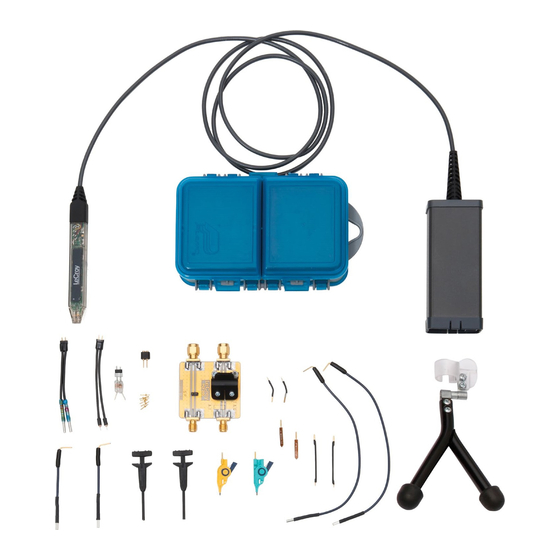
Page 9: Standard Accessories
Instruction Manual Standard Accessories The ZD Series probe is shipped with the following standard accessories: Standard Accessory Quantity Part Number Straight Tip PACC-PT001 Solder-in Lead PACC-ZD002 Right Angle Connector (Long) PACC-LD004 Micro-Grabber PK006-4 Mini-Grabber PACC-CL001 Spring-loaded Ground (Long) PACC-ZD003 Spring-loaded Ground (Short) PACC-CD008 Small IC Adapter PACC-ZD006... -
Page 10: Features And Accessories
ZD500, ZD1000, ZD1500 Features and Accessories The ZD Series probes are provided with numerous features and accessories to make probing and connecting to different test points easier than ever. The small, low mass probe head is designed for ease of use and high performance. -
Page 11: Freehand Probe Holder
Instruction Manual Freehand Probe Holder The FreeHand lets you focus on the oscilloscope screen instead of on maintaining contact to multiple test points. It allows the user to concentrate on what is really important – the waveform. It is designed to keep most of the weight on the probe tip and will prevent lost contact when a bump to the table shakes the circuit under test. -
Page 12: Leads
ZD500, ZD1000, ZD1500 Leads While longer leads provide greater flexibility when connecting the probe to a circuit, the added inductance may degrade the fidelity of high frequency signals. Short and Long Right Angle This lead has a socket on one end and a square pin... -
Page 13: Probe Calibration Fixture
Probe Calibration Fixture The probe deskew fixture (PCF-200) is provided as a standard accessory with ZD500, ZD1000, and ZD1500 probes. The fixture can be used one of two ways: 1. The fixture may be used to determine the effect of probe input loading on the circuit under test and verification of the probe response to the signal being measured. -
Page 14: Probe Operation Handling The Probe
Connecting the Probe to an Oscilloscope The ZD Series probe has been designed for use with Teledyne LeCroy’s WaveSurfer, WaveRunner, WaveMaster, and WavePro platforms equipped with the ProBus interface. When you attach the probe output connector to the oscilloscope’s input connector, the oscilloscope recognizes the probe, provides... -
Page 15: Care And Maintenance Cleaning
The ZD Series probe utilizes fine pitch surface mount devices. It is therefore impractical to attempt to repair in the field. Defective probes must be returned to a Teledyne LeCroy service facility for diagnosis and exchange. Defective probes under warranty are repaired or replaced. A probe that is not under warranty can be exchanged for a factory refurbished probe for a modest fee. -
Page 16: Returning A Probe For Calibration Or Service
Follow these steps for a smooth product return. 1. Contact your local Teledyne LeCroy sales or service representative to obtain a Return Material Authorization. 2. Remove all accessories from the probe. Do not include the manual. - Page 17 Instruction Manual 6. Mark the outside of the box with the shipping address given to you by the Teledyne LeCroy representative; be sure to add the following: ATTN: <RMA assigned by the Teledyne LeCroy representative> FRAGILE 7. Insure the item for the replacement cost of the probe.
-
Page 18: Replacement Parts
ZD500, ZD1000, ZD1500 Replacement Parts The probe connection accessories and other common parts can be ordered through the North America Customer Care Centers. Replacement Part Part Number Straight Tip PACC-PT001 Solder-in Lead PACC-ZD002 Right Angle Connector (Long) PACC-LD004 Micro-Grabber PK006-4... -
Page 19: Performance Verification
Instruction Manual Performance Verification This procedure can be used to verify the warranted characteristics of the ZD Series High Impedance Active Probe. The recommended calibration interval for the models ZD Series is one year. The complete performance verification procedure should be performed as the first step of annual calibration. - Page 20 ZD500, ZD1000, ZD1500 List of Required Equipment. Description Minimum Requirement Test Equipment Examples Digital Oscilloscope ProBus Interface; Windows- Teledyne LeCroy WaveRunner based Zi or WaveSurfer Xs Digital Multimeter (DMM) 4.5 digit Agilent Technologies 34401A with test probe leads or Fluke 8842A-09 DC: 0.1% Accuracy...
-
Page 21: Preliminary Procedure
6.4.1.x or higher. The software version in the test oscilloscope can be verified by selecting Utilities, Utilities Setup... from the menu bar, then the Status tab. Contact your local Teledyne LeCroy representative or visit teledynelecroy.com if the software in your oscilloscope requires updating. -
Page 22: Functional Check
ZD500, ZD1000, ZD1500 Functional Check The functional check will verify the basic operation of the probe functions. It is recommended that the Functional Check be performed prior to the Performance Verification Procedure. 1. Return to the factory default settings by: a. - Page 23 Instruction Manual B. LF Attenuation Accuracy 1. Connect the BNC tee to the output of the function generator. 2. Carefully insert the Straight Tips (supplied in accessory kit) into the sockets of the probe head. Attach the red lead of the mini-grabber to the positive (+) signal input and the black lead to the negative (-) input of the probe head.
- Page 24 ZD500, ZD1000, ZD1500 12. Calculate the gain error by taking 100 * [(Measured Output Voltage) – (Expected Output Voltage)] / (Expected Output Voltage). Record this value as the % Gain Error. Verify that this is within the limits given on the data sheet.
-
Page 25: Performance Verification Test Record
Instruction Manual Performance Verification Test Record This record can be used to record the results of measurements made during the performance verification of the ZD Series Probes. Photocopy this page and record the results on the copy. File the completed record as required by applicable internal quality procedures. - Page 26 ZD500, ZD1000, ZD1500 Items Tested Item Serial Number Date Technician ZD500 ZD1000 ZD1500 Equipment Used Instrument Model Serial Number Calibration Due Date Oscilloscope Digital Multimeter Function Generator Test Record UTPUT OLTAGE Step Description Intermediate Data Output Zero (Test limit 0V ± 5 mV)
- Page 27 Instruction Manual Probe Input Loading Attaching any probe to a test circuit add some loading to the circuit under test. In most applications the high impedance of the probe, compared to the impedance of the circuit under test, imparts an insignificant load to the test circuit.
- Page 28 ZD500, ZD1000, ZD1500 Reference Material Specifications Please refer to the Teledyne LeCroy website at teledynelecroy.com for detailed specification information. Certifications This section contains the probe’s Electromagnetic Compatibility (EMC), Safety and Environmental certifications. EMC Compliance EC D - EMC ECLARATION OF...
- Page 29 The probe is subject to disposal and recycling regulations that vary by country and region. Many countries prohibit the disposal of waste electronic equipment in standard waste receptacles. For more information about proper disposal and recycling of your Teledyne LeCroy product, please visit teledynelecroy.com/recycle. ESTRICTION OF...
- Page 30 Ph: 800-909-7112 / 408-653-1260 customersupport@teledynelecroy.com psgsupport@teledynelecroy.com European Headquarters Singapore, Oscillosocpes Teledyne LeCroy SA Teledyne LeCroy Singapore Pte Ltd. 4, Rue Moïse Marcinhes Blk 750C Chai Chee Road #02-08 Case postale 341 Technopark @ Chai Chee 1217 Meyrin 1 Singapore 469003...
Need help?
Do you have a question about the ZD500 and is the answer not in the manual?
Questions and answers