
Subscribe to Our Youtube Channel
Related Manuals for MKS 49 Series

Summary of Contents for MKS 49 Series
- Page 1 Technology for Productivity SERIES 49 THERMAL MANAGEMENT SYSTEM User’s Manual & Installation Guide...
-
Page 2: Warranty Information
Warranty Service The obligations of MKS under this warranty shall be at its option: (1) to repair, replace, or adjust the product so that it meets the applicable product specifications published by MKS; or (2) to refund the purchase price. - Page 3 Copyright Information All rights reserved MKS Instruments 2019. No part of this work is to be reproduced by any method including photocopying and recording or by any information or retrieval system without written permission of MKS Instruments. Page 2 Series 49 Thermal Management System Instruction Manual...
-
Page 4: Table Of Contents
Contents Warranty Information ............................1 Agency Listing ............................4 Standards and Symbols ........................... 5 General Safety Precautions ........................6 Storage and Cleaning ..........................7 General Specifications ..........................8 S49UL System ............................9 S49UL Installation ..........................12 S49UL Heater Controller ........................17 S49UL LTA+ Controller .......................... -
Page 5: Agency Listing
Safety: EN 61010-1 RoHS Compliant UL Component Recognition UL File E510879 Refer to the Series 49 Declaration of Conformity MKS P/N 20003858-001 for additional compliance information. Page 4 Series 49 Thermal Management System Instruction Manual 20009807-001 - Rev. C – January 2020... -
Page 6: Standards And Symbols
General warning or critical instruction, important procedure, practice, or condition Failure to follow instruction will void warranty and may result in product or personal damage Contact MKS Page 5 Series 49 Thermal Management System Instruction Manual 20009807-001 - Rev. C – January 2020... -
Page 7: General Safety Precautions
MKS offers custom system design for a wide array of applications, is there is any questions on system design or use consult MKS customer service for guidance. -
Page 8: Storage And Cleaning
4. Storage and Cleaning Devices should be stored in their original packaging in a dry, mild temperature environment out of exposure to direct sunlight. Internal electronics are sensitive and may be damage by exposure to high humidity or ambient temperatures in excess of 50 °... -
Page 9: General Specifications
1200 Watts @ 240VAC Maximum Operating 200°C Continuous Temperature Environment 0°C to 60°C Indoor Use Only Relative Humidity 0% to 95% non-condensing MKS Instruments, Inc. Telephone (303)449-9861 Contact Information 5330 Sterling Dr. Toll-Free (800)345-1967 (USA Only) Boulder, Co. 80301 Page 8 Series 49 Thermal Management System Instruction Manual 20009807-001 - Rev. -
Page 10: S49Ul System
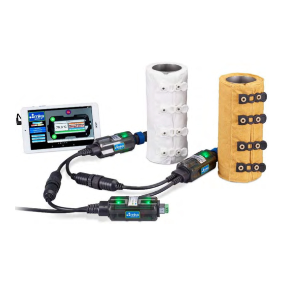
6. S49UL System S49UL System Description: The MKS S49UL Thermal Management System is the 6th generation of MKS thermal product. The focus of S49UL is product Safety (UL Certification, improved insulation), simple and robust communications (out of box RS485 Modbus ready), and high temperature heating (200°C continuous). - Page 11 All interconnects within the system use custom hybrid connectors (Power + Signal). Because of the proprietary connectors to power the Series 49UL System a MKS supplied Power Kit is required. The S49UL Power Kit allows for power injection and communications pass thru, this feature allows for continuous communications on large or high-power installations that require multiple power drops.
- Page 12 The second kit terminates in a Type A USB and is intended for use with the MKS supplied Android App. The Android based user interface application is the only MKS supported S49UL software interface, no other MKS supported software is available at this time.
-
Page 13: S49Ul Installation
7. S49UL Installation The following guidelines are based on a typical installation of S49UL Thermal System, some installations could be different. Caution- The PTFE heater utilizes a fiberglass insulation. While the insulation is contained by the heater shell, use caution if shell is damaged. Caution- The internal surface of the heater (equipment contact side) may be hot. - Page 14 Unpack and verify that there is no damage to any of the heater jackets, controllers, or cables and accessories. If there is any question as to the quality or construction of the product contact MKS immediately. Installation area Inspection of parts and area to be heated for combustibles, sensitive equipment or parts that may be damaged by excessive heat.
- Page 15 Individual control devices are designed to be daisy chained together, however care should be taken to ensure the current draw on a single power adapter does not exceed 10 Amps. MKS provided power adapters use a 10 Amp slow blow inline fuse.
- Page 16 All S49UL interconnections are designed with a keying feature and positive twist lock engagement. When mating connections ensure the male and female connectors are properly aligned, axially rotate the male and female connectors while applying a slight lateral force to locate the keying position. Once aligned press the connectors together while turning the twist locking bale.
- Page 17 If the daisy chain nears 10 Amps of current draw, and there are still additional heaters to be connected to the system, an additional Power Adapter is required. Multiple Power Adapters may be used on a single Heater System or daisy chain line to add as many power drops as necessary.
-
Page 18: S49Ul Heater Controller
8. S49UL Heater Controller Controller Architecture: The S49UL Heater Controller utilizes single microprocessor control with a backup hardware safety. During normal operation both the Primary Control Circuit and the Hardware Safety Circuit are driven by the microprocessor. Downstream of the processor there are two power control relays wired in series, the series configuration provides both the Primary Control Circuit and the Hardware Safety Circuit the ability to directly cut power to the heater jacket. - Page 19 Wiring details The S49UL Heater Controller utilizes a hybrid power and communications interconnect cable. The cable contains the AC power delivery conductors as well as RS485 communications lines. The input and output connector pin outs for the hybrid power and communications line are shown in Figure 11 below.
- Page 20 Visual Indication The S49UL Heater Controller has two sets of LED indicators, the Status LEDs and the Diagnostic LEDs. Status LED’s are located near the heater jacket connection and provide indication of control status. Diagnostic LED’s are located towards the interconnect cable and provide information related to control alerts and errors.
- Page 21 Restore Factory Defaults command via the RS485 Modbus communications (Refer to the Appendix for Modbus Command definitions). Custom settings: Custom Factory Settings are available upon request, contact your MKS representative for further details. General operating behavior •...
- Page 22 HTA parameters – see Figure 13 above), the controller will then indicate a Low Temperature Alert (Status LED’s illuminated solid Blue). • Once the heater is in the At-Temperature range (default: within 20 C of set- point), the Status LED will change from solid Blue to solid Green. •...
-
Page 23: S49Ul Lta+ Controller
The S49UL LTA+ Controller provides a centralized Low Temperature Alert function similar to the MKS Series 46 and Series 48 Legacy LTA (Low Temperature Alert) module. When the S49UL LTA+ is connected to the heater network an addressing algorithm is automatically initiated. - Page 24 Once addressing is complete the S49UL LTA+ will begin polling the S49UL Heater Network querying each individual controller for its operational state and LTA status. If one or more controllers on the network reports an LTA condition, LTA active in the Error Register (See the Appendix) the S49UL LTA+ will generate an LTA condition.
- Page 25 Display Indicators The S49UL LTA+ Controller visual indication is limited to Low Temperature Alert status. The S49UL LTA+ will generate a Low Temperature Alert visual indication any time one or more heaters in the network is registering a local Low Temperature Alert. The S49UL LTA+ also generates a Low Temperature Alert visual indication anytime one or more heaters in the network is reporting a Current State other than Normal.
- Page 26 Process Control Output In addition to the Visual Indication, the S49UL LTA+ Controller includes a Process Control Circuit used to notify the user when one or more heaters in the networked system is reporting an LTA+ condition. The process control consists of three contacts labeled Normally Closed (N.C.), Normally Open (N.O.), and Common (Comm).
-
Page 27: S49Ul User Interface Software
8” screen, such as the Acer Iconia One 8 model. Function and performance for subsequent versions of the Android operating system will be addressed on an as need basis. Please check the MKS website for updated support. - Page 28 Each button can be selected with either a tap or long press to access features according to the descriptions below, See Figure 21 for visual reference. MKS logo: Display the MKS S49 web page when an internet connection is available.
- Page 29 Window. If no controllers are connected a long press of the Devices button enters “Demo” mode. Errors: Indicates the number of controllers on the network with an error condition. Tap this button to display only the controllers with error conditions in the Network Window. Alerts: Indicates the number of controllers on the network with an alert condition.
-
Page 30: S49Ul Basic Communications
11. S49UL Basic Communications General Information The S49 Controllers use Modbus RTU communications over a 2-wire serial interface Communications Settings: The communication data Rate is fixed at 115200 Baud Parity should be set to None Stop Bits set to 1 Each S49UL Heater Controller ships with a default Modbus Device Address of 246 Each S49UL LTA+ Controller ships with a default Modbus Device Address of 247 Two communications cables are offered depending on the termination type required. - Page 31 LTA+ Controller will resume polling the network and reporting the active network condition. The only supported MKS Instruments communications software interface is the S49UI Tablet Application detailed in Section 10 above. Direct connection to a PC, Laptop, PLC, or other Modbus Master Device requires the user to provide their own interface.
-
Page 32: Troubleshooting
This manual covers basic troubleshooting, which allows the user to determine common issues that may occur during the installation and operation of the Series 49 heater system. If the issues cannot be remedied from the steps listed below, please contact MKS for further support. - Page 33 Error Handling for Communication Networks (RS485 Modbus Comms connected) For detailed error conditions and related error handling refer to the S49UL Troubleshooting Guide. For any errors that do not self-clear there are multiple methods to exit the error state and resume normal operation using commands sent via RS485 Modbus Communications.
- Page 34 Contact MKS for further support. operation. Contact MKS for assistance. The unit is no longer Fatal Error - Solid Red. Conditions operational and requires replacement. The unit leading to this type of Error are not field- has entered a non-recoverable state.
- Page 35 Solid Red. Current Output is outside connect heater jacket to controller and apply the expected range. power. If the condition still persists, contact MKS for further support. Disconnect the heater jacket from the controller and verify thermocouple wiring. Error is indicative Low Temperature Threshold Error - of a thermocouple wired in reverse polarity.
- Page 36 Boot Mode - Solid Violet. Control Firmware Update is not being applied, reset has entered Boot Mode. power to the device. If the error persists, update device firmware or contact MKS for assistance. Table 4: S49UL Troubleshoot Guide Page 35 Series 49 Thermal Management System Instruction Manual 20009807 - Rev.
-
Page 37: Accessories And Component Parts
In addition, the Series 49 power adapter uses a 10A fuse, 250 VAC, 5x20mm. This can be ordered from MKS (part number 100020028) or sourced locally. Page 36 Series 49 Thermal Management System Instruction Manual... -
Page 38: Appendix
14. Appendix S49UL Heater Controller - Modbus Register Map Modbus Register Map - S49UL Default Configurable User Register Symbol Access Definition Units Notes Value Range level PSWW User Level Select advanced (level 1) set Register to 0x0123 Binary (291 Decimal); normal (level 0) set to 0 TAG[1 - 8] ascii pair... - Page 39 EOT[1] Equipment on time (hours, lower 16- Values saved every 5 minutes bits) EOT[2] Equipment on time (hours, upper 16- bits) (see) System Command (see CMD page) In: integer command. Out: 0 always Temperature Ambient Sensor °C a.k.a. Cold-junction temperature, a.k.a Electronics Temperature.
- Page 40 S49UL Modbus Command Functions CMD - System Command - Holding Register 54 User Value Command Description level Enter standby mode Device enters standby mode - Relays open, Temperature Control ceases Reset Device Device undergoes a software reset Ping Device displays ping response, initiates a 30sec Ping LED display sequence Clear Errors Clears non-fatal errors in ERR register;...
- Page 41 S49UL Controller Diagnostic Status CDS – Controller Diagnostic Status – Holding Register 61 Description SLA active LTA active HTA active ADC error LTT active Under-current Over-current TC1 Malfunction TC2 Malfunction Safety Relay State (1=closed) Control Relay State (1=closed) (reserved) (reserved) Ambient temperature warning Ambient temperature alert (reserved)
- Page 42 S49UL Error Event[1] Register Error Low - Holding Register 62 Description At-temperature active SLA1 event SLA2 event TC1 Malfunction TC2 Malfunction SLA event HW-FW mismatch HTA active LTA active TDELTA Comparison error CJDELTA Comparison error MAINS_V-heater mismatch error Heater missing error Application load error (reserved) Missing application image...
- Page 43 S49UL Error Event[2] Register Error Low - Holding Register 63 Description Over current event EEPROM i/o error EEPROM checksum error Previous watchdog reset Under current event LTT event (reserved) Ambient temperature alert (reserved) 5V rail fault ADC error Relay failed in closed state Relay failed in open state (reserved) (reserved)
- Page 44 S49UL Current State CUS - Current State - Holding Register 60 Value Description Normal Locked Standby Fatal Bootloader Boot fault Debugging The CUS Register (Holding Register 60) displays the current operational state of the controller This register is a Read Only register...
-
Page 45: Contact
15. Contact For more on Heated Products or literature, contact: MKS Instruments, Inc. 5330 Sterling Drive Boulder, CO 80301 USA Phone: 1-303-449-9861 Toll Free: 1-800-345-1967 Email: mks@mksinst.com Web: http://www.mksinst.com Page 44 Series 49 Thermal Management System Instruction Manual 20009807 - Rev C - January 2020...
Need help?
Do you have a question about the 49 Series and is the answer not in the manual?
Questions and answers