Table of Contents
Advertisement
Quick Links
Technical Description for
Ex-Separator Module iXT0
nd
2
Version
Rev. 02 / 28.08.2017
Original manual: German, rev. 02 as of 22.08.2017
as of Firmware Version: 1.10
NIVUS GmbH
Im Taele 2
75031 Eppingen, Germany
Phone: +49 (0)72 62 9191 0
Fax: +49 (0)72 62 9191 999
E-Mail: info@nivus.com
Internet: www.nivus.com
Advertisement
Table of Contents

Related Manuals for Nivus iXT0

Summary of Contents for Nivus iXT0
- Page 1 Technical Description for Ex-Separator Module iXT0 Version Rev. 02 / 28.08.2017 Original manual: German, rev. 02 as of 22.08.2017 as of Firmware Version: 1.10 NIVUS GmbH Im Taele 2 75031 Eppingen, Germany Phone: +49 (0)72 62 9191 0 Fax: +49 (0)72 62 9191 999 E-Mail: info@nivus.com...
- Page 2 Sharjah Airport International Fax: +48 (0) 58 7602014 Phone: +562 2266 8119 Free Zone poland@nivus.com chile@nivus.com Phone: +971 6 55 78 224 www.nivus.pl www.nivus.com Fax: +971 6 55 78 225 middle-east@nivus.com www.nivus.com page 2 Ex-Separator Module iXT0 - rev. 02 / 28.08.2017...
-
Page 3: Copyrights And Property Rights
Copyrights and property rights Copyrights and property rights This document and its contents are proprietary to NIVUS GmbH and are not to be reproduced or copied without the express written permission of NIVUS GmbH. Violations oblige to compensation. Important Note... -
Page 4: Table Of Contents
Installation of spare parts and parts subject to wear and tear ..19 Construction and functions Enclosure dimensions ..............20 Functional descriptions ..............21 Installation and connection Installation instructions ..............22 page 4 Ex-Separator Module iXT0 - rev. 02 / 28.08.2017... - Page 5 13.1 Connection cable ................24 13.2 Wiring diagram ................. 28 13.3 Sensor connection to Ex-Separator Module iXT0 ......29 13.4 Connection of iXT0 to NivuFlow transmitters ........32 Overvoltage protection ..............34 Maintenance and cleaning Maintenance, material wear and cleaning ........37 Dismantling/disposal ................
-
Page 6: General
READ CAREFULLY BEFORE USE. KEEP IN A SAFE PLACE FOR LATER REFERENCE. This manual is an original instruction for Ex-Separator Module iXT0 and is for the intended use (see chapter “5 Intended use”) of the device. This manual is oriented exclusively to qualified expert personnel. -
Page 7: Applicable Documentation
Colour code for wires and single conductors The abbreviations of colours, wire and components follow the international colour code according to IEC 757. black transparent blue white GNYE green/yellow green yellow brown grey pink Ex-Separator Module iXT0 - rev. 02 / 28.08.2017 page 7... -
Page 8: Safety Instructions
DANGER Danger of electrical shock Indicates a possible danger by electrical power with high risk which may result in death or severe personal injury if not avoid- page 8 Ex-Separator Module iXT0 - rev. 02 / 28.08.2017... -
Page 9: Safeguards And Precautions
It is strictly prohibited to disable the safety devices or to change the way they work. Failure to observe may cause personal injury as well as to sys- tem damage. Ex-Separator Module iXT0 - rev. 02 / 28.08.2017 page 9... -
Page 10: Personnel Requirements
Education and instruction according to the standards of safety engineering regarding the maintenance and use of adequate safety equipment. III. First aid training page 10 Ex-Separator Module iXT0 - rev. 02 / 28.08.2017... -
Page 11: Intended Use
Damages resulting from this are left at user’s risk. The iXT0 is for the connection of NIVUS sensors (specified in chapter “11 Func- tional descriptions”) for use in Ex zone 1. The iXT0 is engineered and manufactured according to the current state of the art as well as to recognised safety regulations. - Page 12 The Ex approval is only valid in connection with the respective indication on the device nameplate. The Ex-version of Separator Module iXT0 is matched to the NIVUS sensors regarding the assessment of intrinsically safe electrical systems according to EN 60079-25.
-
Page 13: User's Responsibilities
− environmental protection Connections As an operator make sure prior to activating the iXT0 that during installation and initial start-up, if executed by the operator himself, the local regulations (such as regulations for electrical connection) are observed. 5.1.1 Keep the manual Keep this manual in a safe place and make sure it is available for the users of this product at any time. -
Page 14: Liability Disclaimer
All operations on the device which go beyond installation or connection measures in principle shall be carried out by NIVUS staff or personnel authorised by NIVUS due to reasons of safety and guarantee. Operate the iXT0 only in technically perfect working order. -
Page 15: Product Description
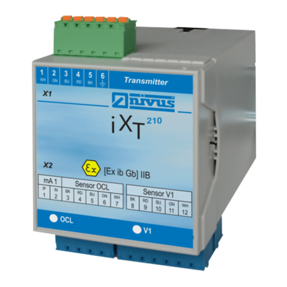
Connection v-sensor 1 (water – cross correlation or surface radar OFR) Connection 2-wire sensor 2 (valid only for iXT04xx) Connection v-sensor 2 (valid only for iXT04xx) Connection v-sensor 3 (valid only for iXT04xx) Fig. 7-1 Overview of Ex-Separator Module iXT0 Ex-Separator Module iXT0 - rev. 02 / 28.08.2017 page 15... -
Page 16: Device Identification
Check the device nameplate to ensure that the device is deliv- ered according to your order. Check if the correct supply voltage is printed on the nameplate. Fig. 7-2 Nameplate of Ex-Separator Module iXT0 page 16 Ex-Separator Module iXT0 - rev. 02 / 28.08.2017... -
Page 17: Device Versions
Product description Device versions The iXT0 is manufactured in different versions which mainly differ by the number of connectable sensors. The article number can be found on the nameplate which is indicated on the hous- ing. Type Description iXT0210 2x RS485-Sensors +... - Page 18 = 253 V AC Outputs 1x transmitter connection RS485 interface Table 3 Specifications Storing When storing, protect the iXT0 from corrosive or organic solvent vapours, radioac- tive radiation and strong electromagnetic radiation. page 18 Ex-Separator Module iXT0 - rev. 02 / 28.08.2017...
-
Page 19: Equipment
One Ex-Separator Module iXT0 - according to delivery note − Technical Instruction with the EC Declaration of Conformity and approvals - where all necessary steps to correctly install and to operate the iXT0 are listed Check additional accessories depending on your order and by using the delivery note. -
Page 20: Construction And Functions
Technical Instruction Construction and functions Ex-Separator Module iXT0 Construction and functions 10 Enclosure dimensions 109,5 Fig. 10-1 Dimensions DIN rail enclosure page 20 Ex-Separator Module iXT0 - rev. 02 / 28.08.2017... -
Page 21: Functional Descriptions
Construction and functions 11 Functional descriptions The iXT0 is an intelligent electronic separation interface which is used between non Ex-area and Ex-zone 1. The iXT0 is conceived for correct Ex-technical separation of the following sensors: NIVUS velocity sensors: − POA-V2 −... -
Page 22: Installation And Connection
Avoid unnecessary movements to reduce the risk of building up static elec- tricity. 12.2 Installation place The iXT0 with DIN rail fastening is conceived for installation in switching cabinets. − Observe adequate ventilation at the installation place e. g. by using a fan or a heat exchanger. -
Page 23: Installation Guidelines
Fasten the rail horizontally in the intended enclosure/switching cabinet by us- ing at least two screws. − Hook the iXT0 into the DIN rail from above and then is snapped into place di- agonally downwards by exerting slight pressure from the front. 13 Electrical installation... -
Page 24: Connection Cable
LiYC11Y 2x1.5 mm² + 1x2x0.34 mm² + PA if possible. Between sensor and iXT0 Maximum cable lengths between sensors and iXT0 if using the NIVUS standard cable LiYC11Y 2x1.5 mm² + 1x2x0.34 mm² + PA: − 150 meters (see Fig. 13-1) −... - Page 25 Installation and connection Between iXT0 and transmitter When installing the iXT0 directly in a switching cabinet or a field enclosure with a connection to NivuFlow xxx using individual wires (in a cable duct or similar) note the following: − Observe to lay power lines and frequency-conducting signal lines separated from each other.
- Page 26 Higher numbers of individual wires need to be combined electrically in a short dis- tance before entering iXT0 and NivuFlow xxx and shall be laid as individual wire with a maximum cross section of 2.5 mm² (clamp or solder connection).
- Page 27 LIYC 11Y 2 • 1.5 mm² + 1 • 2 • 0.34 mm² max. 150 m Fig. 13-2 Connection iXT0 – NivuFlow xxx with NIVUS signal cable max. 300 m NivuFlow air ultrasonic OCL-L1 e. g. A2Y(L)2Y 12 • 2 • 0.5...
-
Page 28: Wiring Diagram
Fig. 13-4 Terminal wiring diagram for iXT0, type 420/421 The X1 terminal block section is designed for connection to a NIVUS transmitter. How to connect the six sensors is described in the X2 terminal block section. Fig. 13-4 shows a separator module for the connection of up to 3 flow veloci- ty sensors. -
Page 29: Sensor Connection To Ex-Separator Module Ixt0
Installation and connection 13.3 Sensor connection to Ex-Separator Module iXT0 The sensor cable is connected to the iXT0 in the terminal block section X2. BK (shield, no earth) outer shield 9.4 V supply + LIYC 11Y 2 • 1.5 mm²... - Page 30 (Ex ib IIB); optional HART shield (if existing) Fig. 13-8 2-wire probe for level measurement to iXT0 2xx/4xx Ex A2Y 2 x 2 x 0.8 or similar max. 150 m (mA2 +) + 22 V Ex 2 - NivuCompact...
- Page 31 Electronic Box EBM with water-ultrasonic sensor CSM and air-ultrasonic DSM to iXT0 2xx/4xx Fig. 13-14 Electronic Box EBM with water-ultrasonic sensor CSM-D to iXT0 4xx Fig. 13-15 electronic Box EBM with water-ultrasonic sensor CSM-D to iXT0 4xx Ex-Separator Module iXT0 - rev. 02 / 28.08.2017 page 31...
-
Page 32: Connection Of Ixt0 To Nivuflow Transmitters
RxTx - max. 150m RxTx + Fig. 13-16 Radar and cross correlation flow velocity sensor to iXT0 4xx (only N7550) 13.4 Connection of iXT0 to NivuFlow transmitters To identify the transmitter type, see the unit’s nameplate. To connect cables observe the notes in chapter “13.1 Connection cable” as well as Fig. - Page 33 PE connection PE (earth) (for SELV connections not required) Fig. 13-18 iXT0 to NF750-M3, N7550 or 1 iXT0 to NF750-M9 Fig. 13-19 iXT0 to NF750-M9 Fig. 13-20 iXT0 to NF750-M9 Ex-Separator Module iXT0 - rev. 02 / 28.08.2017 page 33...
-
Page 34: Overvoltage Protection
Technical Instruction Installation and connection Ex-Separator Module iXT0 14 Overvoltage protection For effective protection of the Ex-Separator Module iXT0 it is necessary to protect power supply as well as mA-inputs and mA-outputs using overvoltage protection devices. NIVUS recommend: − 2-wire connection: DataPro 2x1 24/24 −... - Page 35 Installation and connection Fig. 14-1 Double-side overvoltage protection between iXT0 and NivuFlow 750-S1/SR Ex-Separator Module iXT0 - rev. 02 / 28.08.2017 page 35...
- Page 36 Overvoltage protection sensors to iXT0 e. g. i-sensor DataPro or NivuCompact 2 x 1 24/24 or NivuBar shield (if existing) min. 1.5 mm² Fig. 14-3 Overvoltage protection 2-wire sensor to iXT0 page 36 Ex-Separator Module iXT0 - rev. 02 / 28.08.2017...
-
Page 37: Maintenance And Cleaning
Disregarding may lead to electrical shocks. The iXT0 is designed to be virtually maintenance-free and free of material wear. If required clean the enclosure with a dry antistatic cloth. Do not use any abrasive cleansing agents. -
Page 38: Certificates And Approvals
This technical description uses the designations X1 (to transmitter) or X2 (to sen- sors) for the terminal clamps according to chapter “13.2 Wiring diagram”. For the EC type examination certificate the internal electrical diagrams of the iXT0 modules have been filed. These diagrams use the designations X2, X3, X4, X5 and X6 for the externally accessible terminal strips. - Page 39 Directive 94/9/EC Certificate Number TUV 14 ATEX 142076 for the equipment: Ex-Separator-Module type iXTO-xxx of the manufacturer: NIVUS GmbH (6) Address: Im Tale 2 75031 Eppingen Germany Order number: 8000434847 Date of issue:...
- Page 40 The following executions of the Ex-Separator-Module type iXT0-xxx are available: - iXT0-420: Ex-Separator-Module for connection to 4 x RS485 and 2 x 2 wire sensors - iXT0-421: Ex-Separator-Module for connection to 4 x RS485 and 2 x 2 wire sensors with 1 x HART function...
- Page 41 ,:;;;:;J Schedule EC-Type Examination Certificate No. TUV 14 ATEX 142076 Sensor communication interface RS485 ............in type of protection Intrinsic Safety Ex ib 11B (Terminals X3, 1/2; X4, 1/2; X5, 1/2; X6, 1/2) maximum values per circuit: = 4.1 = 105 mA = 108 mW characteristic line: linear...
- Page 42 Date of issue: 2015-09-17 In the future, the Ex-Separator-Module type iXT0-xxx (type designation with new transformer: iXT0 xxx) may also be manufactured according to the documents listed in the Test Report. The following changes relevant for the explosion protection were performed:...
- Page 43 1. Supplement to Certificate No. TOV 14 ATEX 142076 (17) Special conditions for safe use none (18) Essential Health and Safety Requirements no additional ones TOV NO R D CE R T GmbH, Langemarckstrar..e 20, 45141 Essen, notified by the central office of the countries for safety engineering (ZLS), Iden!.
- Page 44 2015-09-25 Date of Issue: Page 1 of 4 NIVUS GmbH Applicant: Im Tale 2 75031 Eppingen Germany Ex-Separator-Module iXT0-xxx and iXT0 xxx Electrical Apparatus: Optional accessory: Intrinsic Safety Type of Protection: [Ex ib Gb] 11B Marking: Andreas Meyer Approved for issue on behalf of the IECEx...
- Page 45 IECEx Certificate of Conformity Certificate No.: IECEx TUN 14.0014 2015-09-25 Date of Issue: Issue No.: 1 Page 2 of 4 NIVUSGmbH Manufacturer: Im Tale 2 75031 Eppingen Germany Additional Manufacturing location (s): This certificate is issued as verification that a sample(s), representative of production, was assessed and tested and found to comply with the IEC Standard list below and that the manufacturer's quality system, relating to the Ex products covered by this certificate, was assessed and found to comply with the IECEx Quality system requirements.
- Page 46 IECEx Certificate of Conformity Certificate No.: IECEx TUN 14.0014 Date of Issue: 2015-09-25 Issue No.: Page 3 of 4 Schedule EQUIPMENT: Equipment and systems covered by this certificate are as follows: See annexe CONDITIONS OF CERTIFICATION: NO...
- Page 47 --------- � ,---- IECEx Certificate of Conformity Certificate No.: IECEx TUN 14.0014 Date of Issue: 2015-09-25 Issue No.: 1 Page 4 of 4 DETAILS OF CERTIFICATE CHANGES (for issues 1 and above): See annex 1� Annex: _Annexe_issue 1 COC_iXT0xxx_ TUN14.0- 0 14.pdf...
- Page 48 For the following product: Le produit désigné ci-dessous: Bezeichnung: “Ex“ intelligentes "Ex" Trennmodul iXT0 Description: “Ex” intelligent "Ex" Seperation Interface iXT0 Désignation: “Ex”modul isolateur intelligent, type iXT0 Typ / Type: iXT0-xxx / iXT0xxx erklären wir in alleiniger Verantwortung, dass die auf dem Unionsmarkt ab dem Zeitpunkt der Unterzeichnung bereitgestellten Geräte die folgenden einschlägigen Harmonisierungsvorschriften der Union erfüllen:...
Need help?
Do you have a question about the iXT0 and is the answer not in the manual?
Questions and answers