Advertisement
Quick Links
Solidyne
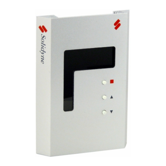
WTS-DB Digital Room Temperature Sensor
The WTS family of Wall Temperature Sensors are designed to be
used with the M2 family of Solidyne controllers. They are designed
with a rugged anodized aluminum housing and a unique one screw
attachment to it's base plate.
The WTS-DB is a digital wall mounted room temperature sensor with
multiple modes of operation. It uses LED's to display room tempera-
ture along with room setpoint and zone override. It also has a built
in light sensor which can be enabled or disabled. The WTS-DB wires
to the M2 family of controllers via CAT-5 cabling and does not have
options for hard wiring.
Specifications
Input Power: Supplied by M2 controller
Temperature Input: 10k Thermistor (Type III)
Operating Temperature: +23°F to +150°F (-5°C to +66°C)
Storage Temperature: -40°F to +230°F (-40°C to +110°C)
Operating Humidity: 10 to 95 %RH non-condensing
Storage Humidity: 10 to 95 %RH non-condensing
Physical Dimensions
WTS-DB Housing:
Figure 1
00-WTS-DB REV 1 11/2005 Solidyne Corporation 4215 Kirchoff Road Rolling Meadows IL (800) 648-3980 www.solidyne.com
TECH/DATA SHEET
Revision 1 12/2007
WTS-DB Backplate:
Figure 2
Wiring
The WTS-DB must be wired to an M2 family controller via the
CAT-5 connection on the back of the device. This method uses
any straight through CAT-5 cable. See figure 3 for the proper
RJ-45 crimping polarity. One end of the CAT-5 cable terminates
into either of the two RJ-45 female connectors on the back of
the WTS-DB. The other end will terminate into the middle M2
RJ-45 female connector. When the WTS-DB is wired via this
method, the temperature sensor input will automatically use
Input #1 (AI1) of the M2 controller that it is attached. The
zone setpoint input will automatically use Virtual Input #1 (VI1)
and the light level sensor will use Virtual Input #2 (VI2) on any
M2 family controller.
Figure 3
WTS-DB
1
Advertisement

Summary of Contents for Solidyne WTS-DB
- Page 1 Virtual Input #1 (VI1) and the light level sensor will use Virtual Input #2 (VI2) on any Physical Dimensions M2 family controller. WTS-DB Housing: Figure 3 Figure 1 00-WTS-DB REV 1 11/2005 Solidyne Corporation 4215 Kirchoff Road Rolling Meadows IL (800) 648-3980 www.solidyne.com...
- Page 2 CAT-5 Wiring: with the supplied 1” screws. An electrical box is not necessary for proper installation of the WTS-DB. The 1” screws have a flat head, if longer screws are needed, please make sure they have a flat head. Once the backplate is installed and wiring is completed, install the WTS-DB sensor onto the backplate at an angle starting at the bot- tom of the sensor as shown in figure 6.
- Page 3 M2-HH tool. All of the WTS-DB settings can be modified by Zone Override Operation select F4 on the M2-HH tool. In all Modes of operation of the WTS-DB, the user can trigger a Changing the Mode of Operation zone override, typically used for after hours operation.
- Page 4 No part of this document may be photocopied or reproduced by any means, or translated to another language without prior written consent of Solidyne. All specifications are nominal and may change as design improvements are introduced. Solidyne shall not be liable for damages resulting from misapplication or misuse of its products.
Need help?
Do you have a question about the WTS-DB and is the answer not in the manual?
Questions and answers