
Subscribe to Our Youtube Channel
Summary of Contents for Comba Telecom RX-4122
- Page 1 CriticalPoint Public Safety BDA UHF PUBLIC SAFETY BI-DIRECTIONAL AMPLIFIER USER MANUAL Public Safety BDA RX-4122 Class A & Class B QE: 1-0-1 Comba Telecom Ltd.
- Page 2 INSTALLATION GUIDE FOR RX-4122 The information contained herein is the responsibility of and is approved by the following, to whom all enquiries should be directed: This is an unpublished work the copyright in which vests in Comba International ("Comba"). All rights reserved.
-
Page 3: Table Of Contents
INSTALLATION GUIDE FOR RX-4122 CONTENTS Section Page CONTENTS ..........................3 INDEX TO FIGURES AND TABLES ..................5 HISTORY ............................. 6 GLOSSARY OF TERMS ......................7 SAFETY NOTICES AND ADMONISHMENTS ................. 8 GENERAL INFORMATION ......................9 EQUIPMENT DESCRIPTION ....................10 FUNCTIONAL BLOCK DIAGRAM ................... 10 EQUIPMENT LAYOUT ...................... - Page 4 INSTALLATION GUIDE FOR RX-4122 APPENDIX C: DECLARATION OF HARMFUL SUBSTANCES AND CONTENT ....52 APPENDIX D: RMA (RETURN MATERIAL AUTHORIZATION) ........... 53 ENU STATUS : 1-0-1 Copyright - refer to title page Page 4...
-
Page 5: Index To Figures And Tables
INSTALLATION GUIDE FOR RX-4122 INDEX TO FIGURES AND TABLES Figure 1: Front, Side and Bottom Views of the PS BDA Enclosure ..............9 Figure 2: PS BDA Functional Block Diagram ....................10 Figure 3: Layout of the PS BDA ........................11 Figure 4: Mounting Rack Overview ...................... -
Page 6: History
INSTALLATION GUIDE FOR RX-4122 HISTORY Change No. Details Of Change 1-0-0 This manual first created and issued in Jan. 2018. 1-0-1 Update to add the part for Class B in ENU STATUS : 1-0-1 Copyright - refer to title page... -
Page 7: Glossary Of Terms
INSTALLATION GUIDE FOR RX-4122 GLOSSARY OF TERMS Abbreviation Definition Automatic Level Control Attenuator Base Transceiver Station Channel Cross Sectional Area Decibel Decibels relative to 1 milliwatt Downlink Donor Terminal Duplexer Frequency Selection Hertz Identification Intermediate Frequency Low Noise Amplifier Line-of-Sight... -
Page 8: Safety Notices And Admonishments
INSTALLATION GUIDE FOR RX-4122 SAFETY NOTICES AND ADMONISHMENTS This document contains safety notices in accordance with appropriate standards. In the interests of conformity with the territory standards for the country concerned, the equivalent territorial admonishments are also shown. Any installation, adjustment, maintenance and repair of the equipment must only be carried out by trained, authorized personnel. -
Page 9: General Information
INSTALLATION GUIDE FOR RX-4122 1 GENERAL INFORMATION The RX-4122 is a new digital public safety Bi-Directional repeater (hereafter referred to as PS BDA) designed to protect the lives of first responders and building occupants. Through the use of digital filtering technology, the RX-4122 helps eliminate adjacent channel interference to allow band selectivity and support 400MHz rebanding. -
Page 10: Equipment Description
INSTALLATION GUIDE FOR RX-4122 2 EQUIPMENT DESCRIPTION FUNCTIONAL BLOCK DIAGRAM DL_01 DL_01 DL_01 DL_01 DL Subband 01 DL Subband 02 DL_02 DL_02 DL_02 DL_02 Mobile Digital Donor Integrated BIAS module UL_01 UL_01 UL_01 UL_01 Mobile UL Subband 01 UL Subband 02... -
Page 11: Equipment Layout
INSTALLATION GUIDE FOR RX-4122 EQUIPMENT LAYOUT Shown below is the internal layout of the PS BDA. OUT1 OUT2 OUT3 OUT4 RF OUT UL PA +28V RF IN RF OUT Loop DL PA UL Filter DL Filter Circulator UL Filter DL Filter... -
Page 12: Equipment Constitution
INSTALLATION GUIDE FOR RX-4122 EQUIPMENT CONSTITUTION The typical PS BDA unit consists of the following components: Downlink Power Amplifier (DPA): It provides power amplification for DL branches. Uplink Power Amplifier (UPA): It provides power amplification for UL branches. Main Control Unit (MCU): The MCU is used to monitor and control the operation of the repeater. It also provides the communication interface for remote control and status indication. -
Page 13: Installation
INSTALLATION GUIDE FOR RX-4122 3 INSTALLATION WARNINGS AND ALERTS Radio Frequency Energies There may be situations, particularly for workplace environments near high-powered RF sources, where recommended limits for safe exposure of human beings to RF energy could be exceeded. In such cases, restrictive measures or actions may be necessary to ensure the safe use of RF energy. -
Page 14: Site Planning Considerations
INSTALLATION GUIDE FOR RX-4122 SITE PLANNING CONSIDERATIONS 3.2.1 SITE PLANNING Site Considerations Outdoor equipment are designed to be waterproof, rainproof, and with snow protection. Temporary protection should be taken when the equipment enclosure is opened for installation or maintenance in an outdoor environment. -
Page 15: Installation Checklist
INSTALLATION GUIDE FOR RX-4122 3.2.2 INSTALLATION CHECKLIST Working space available for installation and maintenance for each mounting arrangement. Ensure unrestricted airflow. Ensure earth ground point is within reach of the ground wire. Ensure a power source is within reach of the power cord and the power source has sufficient capacity. -
Page 16: Installation Procedures
INSTALLATION GUIDE FOR RX-4122 INSTALLATION PROCEDURES 3.3.1 GOODS INWARDS INSPECTION Verify the number of packages received against the packing list. Check all packages for external damage; report any external damage to the shipping courier. If there is damage, a shipping agent should be present before unpacking and inspecting the contents because damage during transit is the responsibility of the agent. -
Page 17: Wall Mounting
INSTALLATION GUIDE FOR RX-4122 3.3.4 WALL MOUNTING Drill four holes on the wall using the position of four holes on the mounting rack as a guide. Fix the mounting rack to the wall using four masonry bolts (M10x110mm). ... -
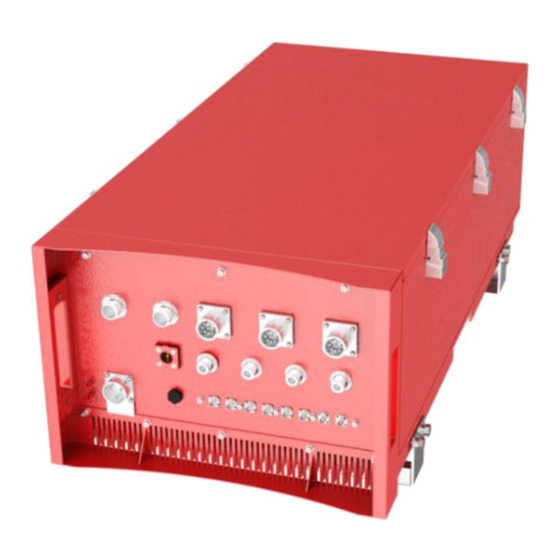
Page 18: Equipment Connectors
INSTALLATION GUIDE FOR RX-4122 EQUIPMENT CONNECTORS 3.4.1 PS BDA CONNECTORS The PS BDA is designed for all cable entries from the right or left of the enclosure, as shown in the following figure. ALM1 ALM2 DT/DL IN MT/DL OUT UL OUT... - Page 19 INSTALLATION GUIDE FOR RX-4122 Table 1: Equipment Connectors Identifier Descriptions Power cable connector for a pre-installed power cord for connection to AC Power (e.g. AC 100-240V 50Hz/60Hz). N-Female connector, It is downlink input port and uplink output port for Duplex mode; It is DT /DL IN downlink input port only for Simplex mode.
-
Page 20: Ps Bda Led Indicators
INSTALLATION GUIDE FOR RX-4122 3.4.2 PS BDA LED Indicators The LED indicators help user to check the equipment status easily. Table 2: LED Indicators Identifier Colour Indication Green Power indicator. ON = power on; OFF = power off. Green Operation indicator, flashes every second to indicate normal operation. -
Page 21: Dry Contact Cable Connection
INSTALLATION GUIDE FOR RX-4122 3.4.6 DRY CONTACT CABLE CONNECTION Below please find the pin definitions of dry contact cables. Table 3: Pin Definition of Dry Contact Cable Pin NO. Input ALM1 CLOSE1 COM1 OPEN1 CLOSE2 COM2 OPEN2 CLOSE3 COM3 OPEN3... - Page 22 INSTALLATION GUIDE FOR RX-4122 Dry contact status: Main Power Normal/Lost dry contact status: Pin definition of ALM and AUX connectors: End of Section ENU STATUS : 1-0-1 Copyright - refer to title page Page 22...
-
Page 23: Commissioning
INSTALLATION GUIDE FOR RX-4122 4 COMMISSIONING PRE-COMMISSIONING TASKS After equipment installation, perform the following steps before equipment powering and commissioning: Verify that the expected voltage, current and power levels do not violate any ratings. Visually inspect the power connection within the equipment. Ensure that the power cable is correctly and securely connected, including the grounding wire, RF cable and other cables. -
Page 24: Commissioning Procedure
INSTALLATION GUIDE FOR RX-4122 COMMISSIONING PROCEDURE Perform the following procedures for system commissioning. Start commissioning guide in WEB GUI Site Information Setting Sub Band Setting Isolation Detection RF Setting Figure 7: Commissioning Procedure ENU STATUS : 1-0-1 Copyright - refer to title page... - Page 25 INSTALLATION GUIDE FOR RX-4122 Table 4: Commissioning Task Explanation Commissioning Tasks Observation 1. Site Information Setting Site ID, Dev ID, Dev Info, Longitude , Latitude, Date/time setting 2. Sub Band Setting Sub Band Frequency setting. 3. Isolation detection Detect isolation of service antenna and donor antenna.
-
Page 26: Web Gui
INSTALLATION GUIDE FOR RX-4122 5 WEB GUI The PS BDA can be monitored and controlled via the WEB GUI; use the following guide to finish system parameter setting and commissioning. WEB GUI CONNECTION Step 1: Connect the OMT port to the PC RJ45 port with the supplied RJ45 cable to set up a physical connection. -
Page 27: Web Gui Introduction
INSTALLATION GUIDE FOR RX-4122 WEB GUI INTRODUCTION After log in, the Web GUI main screen will appear. Indicates the equipment status Shows the basic information about the PS BDA Figure 11: Web GUI Main Screen On Comba Web GUI Home Screen, there are four Menu bars: [Devices], [Commissioning], [Firmware] and [Management]. - Page 28 INSTALLATION GUIDE FOR RX-4122 400MHz Screen-Class A This screen is only available for 400MHz PS BDA Class A Sub band switch status Click to set Selecting frequency sub band Frequency information, , information enable/disable RF switch. Figure 13: 400MHz Screen 1...
-
Page 29: Commissioning]
INSTALLATION GUIDE FOR RX-4122 Click to set Freq Low and High, DL/UL Gain, Enable/disable RF switch. DL Freq Low RF parameters and High of of sub-bands sub-bands Sub-bands switch status Figure 15: 400MHz Screen 5.2.2 [COMMISSIONING] A work flow of the commissioning process is shown on [Commissioning] Screen. Click the [Start] button, the software will guide you through the commissioning step by step. - Page 30 INSTALLATION GUIDE FOR RX-4122 Step 2: Click to finish the Step 1: Click to select the software upgrading. file for upgrading. Figure 17: [Firmware] Screen – MCU Firmware Upgrade Click to swap the firmware to the previous version Figure 18: [Firmware] Screen – Firmware Swap Step 3: Click to finish the upgrading.
-
Page 31: Management]
INSTALLATION GUIDE FOR RX-4122 5.2.4 [MANAGEMENT] Other parameters can be configured on the [Management] Screen. Management menu, click Enter to each page for parameters setting. Figure 20: [Management] Screen ENU STATUS : 1-0-1 Copyright - refer to title page Page 31... - Page 32 INSTALLATION GUIDE FOR RX-4122 There are nine function bars list on the left side of the [Mangement] Screen. Inport&Export Click to import/export the configuration parameters. Figure 21: Management – Import & Export The parameters that can be imported / exported include sub band, alarm enable, ATT value, RF switch, and DL output power.
- Page 33 INSTALLATION GUIDE FOR RX-4122 IP Setting Configure the IP address for remote monitoring. Figure 22: Management – IP Setting Note: For remote monitoring, the IP Address must be set correctly based on the location IP of the remote connection. If more than one piece of equipment is connected to the public network through the same router, the router’s local IP CANNOT be set as 192.168.8.*.
- Page 34 INSTALLATION GUIDE FOR RX-4122 Comm. Setting Figure 23: Management – Comm. Setting Note: There are 4 available communication types: SMS, PS, SNMP and ETHERNET. You can choose a suitable type for remote monitoring. ENU STATUS : 1-0-1 Copyright - refer to title page...
- Page 35 INSTALLATION GUIDE FOR RX-4122 Security Figure 24: Management – Security ENU STATUS : 1-0-1 Copyright - refer to title page Page 35...
- Page 36 INSTALLATION GUIDE FOR RX-4122 Click , [Modify Password] window will pop-up. Figure 25: Modify Password Note: Username cannot be modified. Device Reset Figure 26: Management – Device Reset Note: Click , all the parameters and alarms will be reset to factory default value The Device Reset process will last about 2~4 minutes.
- Page 37 INSTALLATION GUIDE FOR RX-4122 Device Info Click here to get PC time. Input device information. Figure 27: Management – Device Info Note: Users can input a maximum of 30 characters in Device Info. Isolation Figure 28: Management – Isolation Note: This Step is the same as step 5 of [Commissioning].
- Page 38 INSTALLATION GUIDE FOR RX-4122 RF setting Figure 29: Management – RF Setting Alarm Setting Click to start the alarm test. Figure 30: Management – Alarm Setting ENU STATUS : 1-0-1 Copyright - refer to title page Page 38...
- Page 39 INSTALLATION GUIDE FOR RX-4122 Report Figure 31: Management – Report Note: Click Create to create the report (the report can’t be created in IE browser) and make sure that PDF Reader software is installed on the computer. If not, the report will not be visible.
- Page 40 INSTALLATION GUIDE FOR RX-4122 Clear History Alarm Click to clear history alarm Figure 33: Management – Clear History Alarm ENU STATUS : 1-0-1 Copyright - refer to title page Page 40...
-
Page 41: Commissioning Procedure
INSTALLATION GUIDE FOR RX-4122 COMMISSIONING PROCEDURE To complete the installation and commissioning, users need to follow the steps below. Step 1: Click the Menu bar [Commissioning] on home screen, a work flow will be displayed. Figure 34: Commissioning Procedure – Start Step 2: Click to start the process. - Page 42 INSTALLATION GUIDE FOR RX-4122 Figure 36: Device Information Setting It is mainly used to record device location and Date/Time provides a time reference. Clicking the Config Value of Date/Time will update the Date/Time automatically. Step 4 : a. Click to enter to Sub Band Setting/Channel parameters setting-Class A...
- Page 43 INSTALLATION GUIDE FOR RX-4122 Figure 38: Channel parameters setting-Class A Reminder: Make sure the frequency of sub-bands match the actual frequency of filters, or BDA cannot work normally. If the frequency is within [450MHz,470MHz], the bandwidth between DL Freq Low and DL Freq High can be adjusted from 0.2 to 5MHz only.
- Page 44 INSTALLATION GUIDE FOR RX-4122 Figure 39: Device sub-band setting-Class B Reminder: Make sure the frequency of sub-bands match the actual frequency of filters, or BDA cannot work normally. If the frequency is within [450MHz,470MHz], the bandwidth between DL Freq Low and DL Freq High can be adjusted from 0.2 to 5MHz only.
- Page 45 INSTALLATION GUIDE FOR RX-4122 Click to continue. If isolation detection passes, the process will go to Isolation Detection Finish shown as Figure 43 If failed, a Tips window will pop-up, users need to check whether the system isolation is adequate.
- Page 46 INSTALLATION GUIDE FOR RX-4122 Figure 43: Commissioning Procedure – Isolation Detection Finish Step 6: RF Setting Screen for setting the center frequency. Step 2: Input the desired value. Step 1: Click to open the parameter setting page. Figure 44: Commissioning Procedure – Center Frequency Setting...
- Page 47 INSTALLATION GUIDE FOR RX-4122 Step 7: Click to finish the commissioning. In this window, a summary of device setting is shown. Figure 46: Commissioning Procedure – Finish End of Section ENU STATUS : 1-0-1 Copyright - refer to title page...
-
Page 48: Maintenance
INSTALLATION GUIDE FOR RX-4122 6 MAINTENANCE The PS BDA is designed for trouble-free operation and generally does not need maintenance. Maintenance activities should only be carried out by trained personnel. Periodic inspection of the repeater equipment(s) is recommended, the recommended tasks includes: ... -
Page 49: Appendices
10 kHz measurement bandwidth. RX-4122 PS BDA has a noise level of -21 dBm in 100 kHz (equals to -31dBm in 10kHz) measurement at 1 MHz spectrum outside the pass band of BDA and an in-band noise level at around -50 dBm in a 10 kHz bandwidth. - Page 50 DAS due to splitting to multiple antenna and cable losses is significant. As well as the above RX-4122 PS BDA is more likely to be used in a multicarrier environment (more than 2 carriers), which in turn will reduce the intermodulation products produced by the device.
-
Page 51: Appendix B: Tools
INSTALLATION GUIDE FOR RX-4122 APPENDIX B: TOOLS The following are the recommended list of tools for new installation and routine maintenance. Slotted Screwdriver Philips Screwdriver Ring Spanner (Assorted size: 12~20mm) Electrically operated drill and masonry drill bits 12mm ... - Page 52 INSTALLATION GUIDE FOR RX-4122 APPENDIX C: DECLARATION OF HARMFUL SUBSTANCES AND CONTENT Product Name: Public Safety BDA Model: RX-4122 Harmful substance and content of this product as below table shown: Harmful Substance Part Name Cr (VI) PBDE ○ ○ ○...
- Page 53 INSTALLATION GUIDE FOR RX-4122 APPENDIX D: RMA (RETURN MATERIAL AUTHORIZATION) End of Section ENU STATUS : 1-0-1 Copyright - refer to title page Page 53...
- Page 54 INSTALLATION GUIDE FOR RX-4122 ENU STATUS : 1-0-1 Copyright - refer to title page Page 54...
Need help?
Do you have a question about the RX-4122 and is the answer not in the manual?
Questions and answers